Note: Descriptions are shown in the official language in which they were submitted.
CA 02907163 2015-10-05
APPARATUS AND METHOD FOR MEASURING VELOCITY AND
COMPOSITION OF MATERIAL IN AND ADJACENT TO A BOREHOLE
RELATED APPLICATIONS
[0001] This application claims benefit under 35 U.S.C. 119(e) of Provisional
Application Ser. No. 62/060,321, filed October 6, 2014, entitled "Apparatus
and Method
for Measuring Velocity and Composition of Material in and Adjacent to a
Borehole."
BACKGROUND OF THE INVENTION
[0002] 1. Field of the Invention
[0003] This disclosure relates to the field of flow measurement, and in
particular to
apparatus and processes for measuring flow using nuclear or electron magnetic
resonance.
[0004] 2. Description of the Prior Art
[0005] The idea of studying flow by magnetic resonance dates back to the work
of the
early pioneers as described, for example, in Mansfield, P; Morris, P. G.; "NMR
Imaging
in Biomedicine"; Advances in Magnetic Resonance, Supplement 2; 1982; Academic
Press, Inc. Orlando 32887; p.235 section 7.3.5. Prior art devices for flow
measurement or
flow mapping rely on two well-known methods viz. "Time-of-Flight" of saturated
or
unsaturated spins or "Phase-Encoding" by application of a gradient field along
the
direction of flow. (Cho, Z. et. al.; "Foundations of Medical Imaging;" John
Wiley &
Sons, Inc., New York, 1993, p374-386.) Exemplary of the "Time-of-Flight"
method is
U.S. Pat. No. 4,782,295 to Lew and of the "Phase-Encoding" method is U.S. Pat.
No.
5,532,593 to Maneval. Analysis of chemical composition by chemical shift is
discussed
in "Principles of Magnetic Resonance," third edition chapter 4, by Slichter,
C. P.,
Springer-Verlag, N.Y. 1989. The nuclear Overhauser effect is discussed in
chapter 7.
[0006] Those prior art methods employ pulse techniques that broaden the
bandwidth
thereby increasing the noise in the measurement signal. A departure from this
prior
technology is the quasi-steady-state technique in U.S. Pat. No. 6,452,390,
incorporated by
reference herein for all purposes, in which simultaneous spatial and temporal
nutation
1
i
CA 02907163 2015-10-05
. ,
and phase encoding of the moving spins permit simultaneous reception of the
measurement signal in the continuous presence of the adjustable Larmor
frequency
excitation field. The quasi-steady-state condition creates a minimal
bandwidth, limiting
the Johnson Nyquist noise in the received measurement signal. Further, prior
art methods
pertain to measurements within a conduit and not to measurements around the
device
where there may be a strong component of velocity peripheral to the device.
SUMMARY
[0007] The systems, methods and devices of this disclosure each have several
innovative
aspects, no single one of which is solely responsible for the desirable
attributes disclosed
lo herein.
[0008] One innovative aspect of the subject matter described in this
disclosure can be
implemented in a flow measurement device for measuring flow in or around a
borehole
of an earth formation. The flow measurement device can include a magnet
configured to
generate a static solenoidal magnetic field with a field intensity that
decreases in strength
peripherally from the magnet. The flow measurement device can include can
electromagnet disposed around the magnet and configured to generate a time
varying
solenoidal magnetic field. The flow measurement device can include a radio
frequency
(RF) coil disposed around the magnet. The RF coil can be configured to
generate an RF
magnetic field transverse to the static solenoidal magnetic field and rotating
at the
Larmor radio frequency corresponding to the field intensity in a region of
interest around
the flow measurement device. The RF coil can be configured to output a
received signal,
the received signal induced by a magnetic field around the RF coil.
[0009] In some implementations, the electromagnet is a helical coil disposed
around the
magnet. In some implementations, the RF coil can comprise a birdcage coil
disposed
around the magnet. In some implementations, the RF coil can comprise a first
birdcage
coil disposed around the magnet and configured to operate at a first
frequency, and a
second birdcage coil disposed around the magnet and configured to operate at a
second
frequency. In some implementations, the RF coil can comprise a transmitting
birdcage
coil disposed around the magnet and configured to generate the RF magnetic
field, and a
2
I
CA 02907163 2015-10-05
receiving birdcage coil disposed around the magnet and configured to output
the received
signal. In some implementations, the RF coil can comprise a quadrature coil.
In some
implementations, the region of interest around the flow measurement device is
a surface
of a prolate or oblate spheroid having a finite thickness.
[00101 In some implementations, the flow measurement device can include a
controller
configured to calculate a flow velocity through the region of interest around
the flow
measurement device based on the received signal. In some implementations, the
controller can be configured to select the Larmor frequency to correspond to
the region of
interest around the flow measurement device, adjust a magnitude of a time
varying
current applied to the electromagnet to maximize a magnitude of a first side
band of the
received signal, and adjust a magnitude of an RF current applied to the RF
coil to
maximize the received signal. In some implementations, the controller can be
configured
to calculate a mean dwell time of spins in the region of interest around the
flow
measurement device based on the magnitude of the RF current applied to the RF
coil, and
calculate the flow velocity through the region of interest around the flow
measurement
device based on the received signal.
100111 Another innovative aspect of the subject matter described in this
disclosure can be
implemented in a method of measuring flow in or around a borehole in an earth
formation. The method can include inserting a flow measurement device into the
borehole in the earth formation, the flow measurement device comprising a
magnet, an
electromagnet disposed around the magnet, and a radio frequency (RF) coil
disposed
around the magnet. The method can include generating, using the magnet, a
static
solenoidal magnetic field, wherein the static solenoidal magnetic field has a
field
intensity that decreases in strength peripherally from the magnet. The method
can
include generating, using the electromagnet, a time varying solenoidal
magnetic field.
The method can include generating, using the RF coil, an RF magnetic field
transverse to
the static solenoidal magnetic field and rotating at a Larmor radio frequency
corresponding to the field intensity in a region of interest around the flow
measurement
device. The method can include receiving a received signal induced in the RF
coil by a
magnetic field around the RF coil.
3
CA 02907163 2015-10-05
[0012] In some implementations, the method can include calculating a flow
velocity
through the region of interest around the flow measurement device based on the
received
signal. In some implementations, the method can include selecting the Larmor
frequency
to correspond to the region of interest around the flow measurement device,
adjusting a
magnitude of a time varying current applied to the electromagnet to maximize a
magnitude of a first side band of the received signal, and adjusting a
magnitude of an RF
current applied to the RF coil to maximize the received signal. In some
implementations,
the method can include calculating a mean dwell time of spins in the region of
interest
around the flow measurement device based on the magnitude of the RF current
applied to
the RF coil, and calculating the flow velocity through the region of interest
around the
flow measurement device based on the received signal.
[0013] Details of one or more implementations of the subject matter described
in this
disclosure are set forth in the accompanying drawings and the description
below. Other
features, aspects, and advantages will become apparent from the description,
the
drawings and the claims. Note that the relative dimensions of the following
figures may
not be drawn to scale.
BRIEF DESCRIPTION OF THE DRAWINGS
[0014] Figures IA and 1B show a cross-sectional side view and top view of an
example
embodiment of a flow measurement device.
[0015] Figure 2 shows a simplified functional block diagram of an example
embodiment
of a flow measurement device.
[0016] Figure 3 shows a flow diagram of an example method for measuring flow
in or
around a borehole in an earth formation.
[0017] Like reference numbers and designations in the various drawings
indicate like
elements.
4
CA 02907163 2015-10-05
DETAILED DESCRIPTION
[0018] The following description is directed to certain implementations for
the purposes
of describing the innovative aspects of this disclosure. However, a person
having
ordinary skill in the art will readily recognize that the teachings herein can
be applied in a
multitude of different ways. The described implementations may be implemented
in any
device, apparatus, or system that is capable of measuring velocity of flow in
and around a
borehole in an earth formation.
[0019] The following disclosure pertains to measuring velocity of flow and
composition
of material moving within a borehole or peripherally in a surrounding volume.
The
borehole may be present in an earth formation or a man-made structure. The
borehole
may contain a flow measurement device employing nuclear spin or electron spin
magnetic resonance for measurement. Applications of the measurement device
disclosed
herein include hydrocarbon production, hydraulic fracturing, groundwater
migration,
contaminant diffusion, wireline logging, or detecting formation migration or
tectonic
plate shift.
[0020] Measurement of flow by magnetic resonance utilizing time of flight or
gradient
phase encoding techniques are known. Prior methods employ pulse techniques
that
broaden the bandwidth thereby increasing the noise in the measurement signal.
A
departure from this prior technology is the quasi-steady-state technique
described in U.S.
Pat. No. 6,452,390, incorporated by reference herein for all purposes, in
which
simultaneous spatial and temporal nutation and phase encoding of the moving
spins
permit simultaneous reception of the measurement signal in the continuous
presence of
the adjustable Larmor frequency excitation field. The quasi-steady-state
condition
creates a minimal bandwidth limiting the Johnson Nyquist noise in the received
measurement signal.
[0021] The present disclosure differs from the disclosure of U.S. Pat. No.
6,452,390 in
the configuration of its various field inducing components, and in its
technique of flow
measurement. Further, U.S. Pat. No. 6,452,390 does not disclose a method or
apparatus
measure or calculate the peripheral flow in an earth formation surrounding a
borehole.
5
CA 02907163 2015-10-05
Further, the present disclosure also differs from U.S. Pat. No. 6,166,540
(including each
of its divisional and continuation applications) in the configuration of its
various field
inducing components, and its technique of estimating geophysical aspects of an
earth
formation surrounding a borehole within the earth formation.
[0022] A magnet introduced into a borehole can generate a strong magnetic
field both in
the borehole and in the adjacent formation. Spins migrating in this strong
field acquire a
magnetization by T1 relaxation until they enter the region of interest at a
depth of
investigation selected by a radio frequency ("RF") magnetic field and acquire
a
transverse component of magnetization, which can induce a voltage in the
receiver coil.
As used herein, the depth of investigation refers to a distance to the region
of interest
from the center of the flow measurement device. An electromagnet adjacent to
the strong
magnet can produce a weaker slowly time varying component of that strong
magnetic
field, creating phase modulation of the spins and permitting detection in the
presence of
the continuous radio frequency field. Adjusting the strength of the radio
frequency field
for maximum received signal can yield a known function of the mean dwell time
of the
spins in the volume of, and at the depth of, investigation. The following
background is
helpful to understanding the flow measurement device described herein.
[0023] Introduction to Simultaneous Nutation and Periodic Phase Encoding of
Moving
Spins ("SNAPPEMS")
[0024] Transient response of spin systems have usually been described by
solutions to
the Bloch equations (Slichter, C.P. "Principles of Magnetic Resonance", Third
Edition.
Springer-Verlog 1989, op. cit., p.33, Ch. 2) which describes the magnetization
as a
function of both the applied magnetic fields and the relaxation effects on a
phenomenological basis. Solutions to the Bloch equations require assumptions
about the
magnitude of these parameters and prescription of boundary conditions,
creating a
differential system applicable to a particular set of circumstances. To
simplify this
process further, the description below begins with the equation of motion of
an isolated
spin, modeled as gyroscopic precession driven by moments created by applied
magnetic
fields, then introduces the total magnetization as a function of spin density,
and finally
6
CA 02907163 2015-10-05
limits the applicability of the equations so derived by the relationship
between the times
of the event sequence to the relaxation times.
[0025] Gyroscopic Precession
[0026] "A rigid body free in space without any constraints can rotate
permanently only
about a principal axis of inertia" (Den Hartog, J.P., "Mechanics". McGraw Hill
Book
Co., 1948. Dover Publications Inc. 1961, op. cit., p.315 No XII). "If a rigid
body rotates
with speed col about a principal axis of inertia, and with co2 = co3 = 0 about
the other
two principal axes, then the angular momentum vector (i.e. moment of momentum
vector) IT/' has the same direction as the angular-speed vector col (which is
along the axis
of rotation)," (Hartog, J.P., op. cit., p.315 No VIII). "Angular velocities of
a rigid body
about various axes in space, all intersecting in a point, can be compounded
vectorially
into a resultant angular speed about THE axis of rotation" (Hartog, J.P., op.
cit. p.314 No
III).
[0027] We infer from the last statement that the resultant angular speed w1
about THE
5 axis of rotation taken as the resultant angular velocity ro can be
decomposed into a vector
sum of angular velocities E an. Further, taking the rigid body as having mass
symmetrically distributed about all axes through the center of mass yields a
constant
scalar moment of inertia /0 about all axes, leading to the desired result
decomposing the
angular momentum vector Al :
M= loa oan.
[0028] From Newton's equations (Hartog, J.P., op. cit., p.277, eq.27b), with
!VG being the
moment of external forces about the center of mass:
d d
G = ¨I (4.1 =I¨I co
dt dt
[0029] Thus the vector sum of the moments of a set of external forces E fiGn
equals the
time rate of change of the total angular momentum /0a, i.e:
7
CA 02907163 2015-10-05
d d
RG =IR G - I
dt dt n"
[0030] Gyromagnetic Ratio
[0031] Taking the rigid body as having a symmetrical distribution of charge
about the
center of mass creates a magnetic moment 4.1. about any axis of rotation
proportional to the
angular velocity (7) about that axis of rotation (Smythe, W.R. "Static and
Dynamic
Electricity", Second Edition. McGraw Hill Book Co 1950, op. cit., p.260) where
each
element of charge dq at distance r from the axis of rotation creates an
element da of this
magnetic moment P where, by definition of the magnetic moment,
d4u = (7tr2)(r)¨dq
2n-r
(Balanis, C.A., "Advanced Engineering Electromagnetics". John Wiley and sons
1989,
op. cit., p.87, eq.2-82).
[0032] Each element of mass dw at distance r from this axis of rotation
creates an
element of the angular momentum (moment of momentum) dM of (Hartog, op. cit.,
p.2'76)
d/Ti = (r)(r63)dw (Balanis, op. cit., p.87, eq. 2-83).
[0033] The ratio is assumed to be a constant:
cig (aq)
= _
- y (Balanis, op. cit., p.87, eq. 2-84).
dM 2 dw
y being a scalar constant termed the gyromagnetic ratio. Integrating, with
boundary
condition 4 = 0 when M = 0 yields:
[0034] General Equation of Motion of an Isolated Spin
[0035] A magnetic moment 4 subjected to a field of magnetic induction will
experience a mechanical moment (torque) )4' such that:
8
CA 02907163 2015-10-05
.1f7i = 4 x 13 (Smythe, W.R., op. cit., p.261)
[0036] In free space of permeability 0, the magnetic induction /4 is
proportional to the
magnetic field intensity Fi :
=
[0037] Equating the rate of change of the angular momentum to the applied
mechanical
moment (torque) yields
x = (Slitcher, op. cit., p.11, eq. 2.1).
[0038] Multiplying by the gyromagnetic ratio 7 and substituting = yiti and ri
= õLori
yields
x (Y[to)14 = r
[0039] Defining y' = ypto yields the equation of motion of a magnetic moment
(spin)
subjected to a magnetic field intensity ii:
[0040] Dividing by it yields the instantaneous angular velocity of a magnetic
moment
(spin) 4 subjected to a time varying ambient magnetic field intensity Fi :
x y ¨ - ' d ¨dt ,
which is a linear differential equation with constant coefficients, allowing
superposition.
[0041] Decomposing ri into Ho, hp, and hn
[0042] Define an orthogonal coordinate system for tit and if as where +.5;
forms Gaussian planes everywhere orthogonal to 2.. This allows decomposition
of the
ambient magnetic field intensity 14 such that:
9
CA 02907163 2015-10-05
II = [Ho + hp COS(nt)ji finelY 'Hot,
where Ho is a strong non-time variant ambient magnetic field intensity, hp is
co-aligned
with Ho and sinusoidally periodic at frequency 12 , and hr, is everywhere
orthogonal to Ho
rotating in the local orthogonal Gaussian plane at angular velocity y'H =
ypoHo =
yBo = coo, which is the Larmor frequency.
[0043] Equation of Motion of SNAPPEMS
[0044] Substituting and rearranging in differential form
dip = (fp x1102)dt + (ft, x [y' hp cos(flt)]i)dt + (fp x hneh"1109dt
[0045] The first term creates a constant precession of 1,4 of angular velocity
y'Ho about
the 2' axis.
[0046] The second term creates a periodic precession of 1,4 of peak angular
velocity y'Hp
and temporal frequency SI about the axis.
[0047] The third term represents a constant precession of 1,2 of angular
velocity y'h,
about an axis perpendicular to the 2. axis, said axis rotating with angular
velocity y'Ho in
the + j5; Gaussian plane.
[0048] These three instantaneous angular velocities add vectorially to a
resultant angular
velocity, which when integrated over time, creates the locus of i in space.
[0049] If yihn yi hp << y'H0, the locus of the unit vector ft, describes
a
serpiqinous line on a unit diameter sphere, said sphere rotating with an
angular velocity
y' Ho in the +j Gaussian plane (Slichter, op. cit., Ch. 2.4, p.20)
[0050] Output Voltage in Receiver Coil
[0051] Define the transverse magnetization /TIT as the projection of the
magnetic moment
4.1 on the + j5; Gaussian plane, which plane is transverse to the axis, such
that:
i
CA 02907163 2015-10-05
1-17. . (u. sin 0)ej ,
where 0 is the colatitude of ii with respect to the i axis, and cp is the
longitude taken from
a zero meridian through the i and g axes. The instantaneous angular velocity
of -117, in
the 5c.' + j5" Gaussian plane then is:
y'hp cos(clt) + Y'Ho
creating a phase incrementation cp of PT at time t of
cp = i -1:43Tdt =--." sin(S2t) + y'Hot .
0.
o
[0052] A coil of N turns, with its area vector along the -.i axis will subtend
the rotating
magnetization of such that:
[
y'h,
, = /2 sin 0 (sin (p) = (p. sin 0) sin ¨SI--1-sin(12t) + y'Hot .
[0053] By Faraday's law, the voltage induced in the coil is
r
y hP
V = /Vito, ¨ = Ni.to ((ii sin 0) Of fhp cos(120-1-ymo) COS - sinalt) + y'Hot
dt fl,
iti
Y P
+ sin[¨sinGilt + Y11001(12 cos 0) (-1)
n dt
d0
Since ¨dt ?_-' y'
ll., << y' hp << y'Ho :
V=L--' N( 01 sin 0)(y'll0) (cos [).1Pi2 sin(f2t) + y'Hoti),
to where N is the number of turns in the coil, [10 is the permeability of
free space, Ho is the
main magnetic field intensity, y' is the gyromagnetic ratio [toy , hp is the
peak magnetic
field intensity of the phase modulating field of temporal frequency SI, and 0
is the
colatitude of the magnetic moment (spin) of magnetic field intensity pt.
[0054] The Fourier transform of V with respect to time is
11
CA 02907163 2015-10-05
+oo fhP
31/16) = RA 11, 1111(-41 n) 6[60.--(y'Ho+nn)] atco+(y' Ho+nn)i)1'
n=¨oo
where A = A (uop.)040H0)y sin O. (Poularikas, A.D. ed. "The Transforms and
Application Handbook" CRC IEEE Press 1995, op. cit. p. 221, eq. 2.82)
[0055] Phase Modulating Field hp
[0056] Three voltages are induced in this receiver coil; the first by hp at a
low frequency
12, the second by hp of radio frequency (RF) frequency y'Ho = yptoHo = yBo =
coo, and
the third by the precession of the magnetic moment /.7 (spin) consisting of a
central
frequency coo with an infinite number of sidebands spaced about this central
RF Larmor
frequency coo at frequency intervals a These sidebands permit adjustment of hp
for the
io maximum energy transfer condition 0 = Tr since they can be detected in
the presence of
the Larmor RF frequency coo and the phase modulating low frequency SI by
rejecting
these latter frequencies with circuit filters and/or by detection,
heterodyning, and
demodulation techniques employed in standard radio receivers. This received
first
sideband voltage is maximized if the argument of the first sideband is
adjusted so that:
(¨Y1hP) J (1.8) 0.582 (Abramowitz, op. cit. p. 390)
n
yielding
yfhp= yitohp = ybp = 2n(42.589x10⁶)
1.8 1.8 1.8 1.8 UP,
then the side band frequency fp 23.6X106 = bp where 2n-fp = SI The peak
excursion
of the magnetic moment (spin) from the plane containing Hoand orthogonal to hp
is 1.8
radians, or 103 degrees.
[0057] Thus, 11 and hp are so defined but are independent of the main magnetic
field
strength Ho or Larmor frequency y'Ho = ypoH = yBo = coo.
[0058] Flow Meter Application
12
CA 02907163 2015-10-05
[0059] If the magnetic moments (spins) 4 of spin density D dwell in a space
containing
Ho and hp for a time sufficient to create significant magnetization Fri = D4
(Slichter, op.
cit. Ch.2.11, p.51) and then move through a space additionally containing hn.
for a dwell
time such that nutation occurs through an angle 0 = it, maximum energy is
absorbed by
the magnetic moments (spins) 4 (Balanis, op. cit. p.86, eq.2-81).
[0060] A medium (lattice) containing a distribution of magnetic moments 4
(spins)
traversing a conduit of length L1, in which these magnetic moments are
subjected to both
a strong magnetic field intensity Ho and co-aligned weak component hp,
sinusoidally
varying with a period n , will absorb energy from the magnetic moments by
first order
kinetics, opposed by random thermal motion, creating a magnetic field
intensity Fri such
that
-4=--4 (110 + hp COS nt) (1 e-t/To,
771 X
(where denotes both spatial vector and temporal phasor) (Slichter, op.
cit., p.51-59,
ch.2.11), => being the complex susceptibility (Slichter, op. cit., p.35-39,
ch.2.8), T1 the
X
spin-lattice relaxation (Slichter, op. cit., p.8, eq.1.31)
[0061] If a subsequent short segment of this conduit of length L2 is
additionally subjected
to a continuous magnetic field intensity Yin orthogonal to II, and rotating in
the x, jy
Gaussian plane at the Larmor angular velocity y'Ho = yptoHo = yBo = wo, the
magnetic
moments 4 (spins) will precess about -IL at an angular velocity y'fin such
that:
= = ¨`ftfor y'hnclt ; 0 = y' hriT,
where T is the dwell time of 4 in Ji and 0 is the colatitude of the plane
containing both
r, and the magnetic moment with respect to the 2 axis defined by Flo
(Slichter, op.cit.,
Ch.2.4, p.20). This will create transverse magnetic field intensity mT such
that:
mT = m sin 0 = sin y'hnT
13
CA 02907163 2015-10-05
[0062] If the medium (lattice) traverses the conduit at a mean velocity v, the
mean
distance 1 traversed in the conduit section of length L2, in time Twill be
/ = VT
and mT = m sin HY'h 1),
as (increases from zero to L2. If the receiver coil of N turns of width W and
length L2
has an area vector A that is aligned with the transverse magnetic field
intensity mT along
the length L2 of the conduit, then the total magnetic flux (1) coupled to the
receiver coil
becomes
L2
1)
( = W f mTd1
rh,L2
= N it0WmL2 sin (Yi ________________ hn 1) dl = N 0WmHyvhn) v sin xdx
2 V
CP = N 1.10Wm(-- -)[1 ¨ cos (L¨in L2)1 = (NWL2)( 0m) 1-Cosa
rhn a
vihn
where a = L2 =
d1) (sin a 1- cos cr;
¨( = (NW L2)(170 2
,10
da a a )
For maximum (I), ¨d: = 0, therefore, cos a + a sin a = 1, and a = n27r or a
2.33.
Then v = L2.
2.33
Since, for water protons, y' = [toy = (4Trx10-7)(27r)(42.6x10⁶)
then V (144.5L2)hn
is the optimum flowmeter equation, with hn adjusted in each measurement of
velocity v
for maximum sideband voltage, Ji ( ) 0.582/0, at frequency coo + fl.
[0063] Precision
c/c13 sin a 1¨ cos a}
¨da = (NW L2)( 0m) ( a )
a 2 _________________________________________________
14
CA 02907163 2015-10-05
ect) ((cos a sin a) (sin a 1
¨ cos a)
da2 = (NW L2)( 0m) a 2a3 )
a )
= (NW I, 2)(1,1070 (cos 2 sin: + 21¨cos cc)
oc a a3 .
But cos a + a sin a = 1, cos a = 1 ¨ a sin a, for ¨c/c13 = 0.
da
d2 CI) 1 sin a sin a)
d 2 1113_0 = (NWL2)010M) (¨a ¨ sin a ¨ 2 2 ¨ + 22
a da- a
1
= (NWL2)(0m) (¨a ¨ sin a) = (NW L2)(ptom) ( 2.33 1 2.33 sin (360))
27r
= (NW L2)( 0m) (0.429 ¨ sin 133.4)
d24,
¨ lacp = (NWL2)(it0m)(-0.298).
da2 ¨da=
[0064] The rate of change of slope of output voltage about the maximum value
of a is
proportional to the magnetization 771+ and the receiver coil area WL2.
[0065] Scale Restrictions on L2, f p by Range of Velocity v
[0066] The Fourier transform analysis of the receiver coil voltage, as
expressed, applies
strictly to a non-bounded function. The observation of this voltage is
truncated in time by
the dwell time r2 of the magnetic moments 4 (spins) in the short conduit
segment of
to length L2. This truncation is the mathematical equivalent of
multiplication by a unit
pulse function of duration T2, creating convolution of the Fourier transform
by a sine
function (Poularikas, op. cit., p.6, eq. 4, 6, and p.204, Table 2.4)
broadening each element
of the sidebands and degrading signal-to-noise ratio, since the minimum noise
power is
proportional to sideband width.
[0067] This is obviated by making the frequency 12 of the phase modulating
magnetic
field intensity hp sufficiently large so that
2m 1
CI = 27rfp ¨ , fp ¨
T2 T2
noting fp 23.6x106 = brand vL2
= 7-2, the transit time through L2.
CA 02907163 2015-10-05
10068] Since there are inhomogeneties in the magnetic field intensities
ambient to each
magnetic moment (spin) and each such magnetic moment is subject to random
displacement by both passive diffusion and active fluid turbulence, there is a
progressive
loss of coherence of the magnetic moments created by random phase
incrementations chp
during transit of the medium (lattice) through the short receiver section of
the conduit of
length L2. These are the T effects progressively diminishing coherent
magnetization
along the segment of length L2 of the conduit by first order kinetics
(Slichter, op. cit.,
p.34, 35).
[0069] Thus, 7-2 << T to preserve signal strength and, therefore, precision.
[0070] Noise Budget
1) Major Components:
a) Main Magnet plus RF shielding
i) Resistive ¨ D.C. power supply and hot coil can be source of
RF noise
mutually coupled to receiver coil.
ii) Permanent ¨ Thermal noise capacitively coupled to receiver coil.
iii) Superconducting ¨ minimal noise.
iv) Hybrid ¨ as above.
b) Phase Modulating Coil and ELF Power Supply
i) Stable C.W. ELF (1-10 kHz) Power Supply must be monochromatic
and with constant current output.
ii) Phase Modulating Coil of low resistance to reduce thermal noise
mutually coupled to receiver coil.
c) RF Transmitter Coil and Adjustable RF Power Supply
i) RF Transmitter Coil of low resistance to reduce thermal
noise
mutually coupled to receiver coil.
16
CA 02907163 2015-10-05
ii) Monochromatic RF Power Supply auto-tuned to the slightly variable,
Larmor frequency.
d) RF Receiver Coil and RF Receiver Circuit.
i) RF Receiver Coil of low resistance forming a very high Q resonant
circuit.
ii) RF Receiver Circuit impedance matched to RF Receiver coil with
cross-correlation to RF Power Supply frequency to extract received
signal from received noise.
e) Controller Circuit Controls RF Transmitter Power Supply Larmor frequency
and measured value of current output to RF Transmitter Coil to achieve
maximum RF Receiver Circuit output.
2) Schedule of Major Components:
a) Main Magnet
b) Phase Modulating Coil
c) Phase Modulating Coil Power Supply, ELF (1-10 kHz)
d) RF Transmitter Coil
e) RF Transmitter Coil Power Supply, Larmor frequency
f) RF Receiver Coil
g) RF Receiver Circuit
h) Controller Circuit
i) Conduit and Mechanical Supports and Seals
3) Noise Contributions in Order of Severity:
a) The two power supplies should be monochromatic dedicated circuitry.
b) The three coils must be high Q, low resistance, low noise.
c) The receiver coil must be a narrow passband resonant circuit that does not
oscillate when impedance matched to the receiver.
17
CA 02907163 2015-10-05
[0071] Signal Strength
[0072] Signal strength varies as less than the square of the Main Magnet field
strength,
directly with length L1 of the Main Magnet, and linearly with the area of the
Receiver
Coil, the latter being a function of conduit diameter. Field homogeneity in
the receiver
section L2 is a function of the length of the Main Magnet before and after L2.
The dwell
time Ti in the magnetizing section of length L1 must be a significant fraction
of the spin-
lattice relaxation time of the moving material T1.
100731 Rangeability
[0074] The Range of Velocity v should be converted to dwell times t1 and T2
for
lengths L1 and L2, for each flow range application, and compared to T1 spin-
lattice and
spin-spin relaxation times for each class of material measured.
[0075] With this background, a flow measurement device implementing these
principles
can be described.
[0076] Figures IA and 1B show a cross-sectional side view and top view,
respectively, of
an example embodiment of a flow measurement device 100. The flow measurement
device 100 includes a magnet 101 having north and south poles, an
electromagnet 102,
and radio frequency ("RF") coils 103 and 104. The flow measurement device 100
is
configured to insert into a borehole 105 of an earth formation 106.
[0077] The flow measurement device 100 can include a magnet 101. The magnet
101
can generate a static magnetic field around the flow measurement device 100
that is
generally solenoidal in shape. The strength of the static magnetic field is
not critical to
the function of the flow measurement device 100, but can generally be in the
range of
several Gauss to several Tesla. The strength of the static magnetic field
generated by
magnet 101 can decrease in strength peripherally from the magnet. The magnet
101 can
include a permanent magnet. The magnet 101 can alternatively include a
conventional or
superconducting electromagnet. The magnet 101 can be of any size or shape
appropriate
to the dimensions of the borehole and the flow measurement application for
which it will
be used, including a long or short cylindrical shape.
18
CA 02907163 2015-10-05
[0078] The flow measurement device 100 can include an electromagnet 102. The
electromagnet 102 can be configured to generate a time varying magnetic field
around
the flow measurement device 100 that is generally solenoidal in shape. The
electromagnet 102 can be of any type suitable for generating a solenoidal
magnetic field
of roughly the same relative distribution as the static magnetic field. The
electromagnet
102 can take the shape of a helical coil surrounding the magnet 101. The
strength of the
time varying magnetic field generated by the electromagnet 102 can vary
linearly with
the application of a time varying current through the electromagnet 102. The
strength of
the time varying magnetic field generated by the electromagnet 102 can be
relatively
weak compared to the strength of the static magnetic field; for example, a
fraction of a
Gauss to several Gauss. The frequency of the time varying magnetic field
generated by
the electromagnet 102 can be relatively low in frequency compared to the
frequency of
the RF magnetic field generated by the RF coils 103 and 104.
[0079] The flow measurement device 100 can include radio frequency ("RF")
coils 103
and 104. The RF coils can be configured to generate a time varying magnetic
field hi
transverse to the Ho static solenoidal magnetic field generated by the magnet
101 and
electromagnet 102. The RF coils 103 and 104 can be a single coil or made up of
more
than two coils. The RF coils 103 and 104 can be a single coil configured to
both transmit
and receive time varying magnetic fields. Alternatively, separate RF coils 103
and 104
can be employed as a transmit coil and a receiving coil, respectively. The RF
coils 103
and 104 can be of a birdcage or quadrature design, or any other coil, cage, or
antenna
structure suitable for directing an RF magnetic field outward from the flow
measurement
device 100. In one embodiment, the RF coils 103 and 104 comprise a
transmitting
birdcage coil disposed around the magnet and configured to generate the RF
magnetic
field, and a receiving birdcage coil disposed around the magnet and configured
to output
the received signal. In another embodiment, the RF coils 103 and 104 could
comprise a
first birdcage coil disposed around the magnet and configured to operate at a
first
frequency, and a second birdcage coil disposed around the magnet and
configured to
operate at a second frequency. The RF coils 103 and 104 can be tuned to
resonate at the
desired frequency of operation. Tuning of the RF coils 103 and 104 can be
accomplished
mechanically or electrically by adjusting a component such as a variable
capacitor or
19
CA 02907163 2015-10-05
=
inductor. An example of an electrically tunable capacitor is a varicap or
varactor diode.
An example of a mechanically tunable capacitor is a variable or tuning
capacitor. The RF
coils 103 and 104 can have a high quality factor ("Q") for improved efficiency
of
transmission and receipt of time varying magnetic fields. The RF coils 103 and
104 can
be adjusted by these or other methods to generate a time varyinghl magnetic
field
rotating at the Larmor frequency coo = yho corresponding to the Ho static
solenoidal
magnetic field intensity 110 in a region of interest around the flow
measurement device
100. The region of interest can take the shape of a barrel shaped prolate or
oblate
ellipsoidal surface having a finite thickness generated about the centerline
of the flow
measuring device 100. The RF coils 103 and 104 can be configured to output a
received
signal induced by the magnetic field about the RF coils 103 and 104.
[0080] Multiple RF coils 103 an 104 can be employed to measure the relative
abundance
of two different spin species; for example, detection and measurement of both
1H and 13C
by the same flow measurement device 100. Exciting RF coils 103 and 104 with
frequencies selected for two different spin species permits implementation of
the nuclear
Overhauser effect yielding the mean dwell time of, e. g., 1H and 13C, thereby
implementing a multiphase "cut meter" or wireline logging modality. Such a
system may
be valuable, for example, for measuring the relative abundance of hydrocarbons
versus
brine in the region surrounding the flow measurement apparatus. Such
information can
be valuable when searching for hydrocarbon deposits.
[0081] In operation, the magnet 101 and electromagnet 102 can create a strong
solenoidal
field with a weak slowly time varying component in the borehole 105 and in the
surrounding disturbed and undisturbed earth formation 106. The RF coils 102
and 103
can create an adjustable RF magnetic field essentially orthogonal to the
solenoidal field.
The RF magnetic field rotates at the Larmor frequency and causes the spins to
nutate with
increasing angle with respect to the strong magnetic field, permitting
reception of a
received signal induced by a magnetic field created by the nutating spins at
sideband
frequencies slightly displaced from the Larmor frequency. Selecting the Larmor
frequency selects the depth of investigation, where the depth of investigation
represents
the distance from the flow measurement device 100 to the region of interest of
spin
CA 02907163 2015-10-05
activation about the flow measurement device. That is, for a given strength of
the static
solenoidal magnetic field Ho, adjusting the frequency of the RF magnetic field
generated
by the RF coils 103 and 104 controls at what distance from the flow
measurement device
100 spins will be affected. An RF magnetic field having a higher frequency
will activate
spins relatively closer to the flow measurement device 100, and an RF magnetic
field
having a lower frequency will activate spins relatively further from the flow
measurement
device 100. The strength of the slowly varying component of the solenoidal
field is
adjusted for optimum signal reception of the first sideband frequencies from
the depth of
investigation.
[0082] The conditions generated by the flow measurement device 100 create both
nutation, with increasing flip angle, and periodic phase modulation of the
rotational
Larmor frequency of the spins. The received signal then induced in the RF
coils 103 and
104 is sinusoidal with slowly varying frequency whose Fourier transform yields
a central
Larmor frequency and discrete side bands displaced by the phase modulation
frequency.
is These side bands can then be detected in the presence of the strong
Larmor excitation
frequency field by means known in the art including heterodyne frequency
shift,
quadrature detection, and cross correlation in a lock-in amplifier. Adjusting
the strength
of the Larmor excitation frequency field for maximum received signal yields a
known
function of the mean dwell time of the spins at the depth of investigation.
This permits
measurement of the peripheral velocity of flow in the formation or the linear
velocity of
flow within the borehole, depending on the selected depth of investigation.
[0083] In use, the Larmor coo for the desired depth of investigation can be
set¨this can
be the frequency of the signal transmitted by the RF coils 103 and 104, and
hence the
frequency of the RF magnetic field. The current in electromagnet 102 can be
adjusted to
maximize the value of the first side band about the Larmor frequency from the
received
signal induced in the RF coils 103 and 104. The optimum current can be set
experimentally for the given depth of investigation. The exact optimum current
for the
exact maximum signal need not be established precisely, but in general a
greater received
signal can yield better measurements. To estimate peripheral velocity of flow,
the
magnitude of the current in the RF coils 103 and 104 can be set for maximum
received
21
CA 02907163 2015-10-05
signal. The magnitude of the RF current is a linear function of the mean dwell
time of
the spins in the depth of investigation. Extrapolating from the mean dwell
time of spins
through the region of interest can yield the average velocity of those spins
either through
the formation 106 or linearly along the borehole 105.
[0084] Figure 2 shows a simplified functional block diagram of an example
embodiment
of a flow measurement device 200. The flow measurement device 200 includes
magnet
101, electromagnet 102, and RF coil 103 described previously. The flow
measurement
device 200 can include a controller 210, a function generator 220, an
amplifier 230, a
function generator 240, an amplifier 250, an amplifier 260, and an analog-to-
digital
convertor ("ADC") 280.
[0085] The flow measurement device 200 can include a controller 210. The
controller
210 can comprise a microcontroller, a microprocessor, an application-specific
integrated
circuit, a field-programmable gate array, CPU, personal computer, or any other
device
capable of controlling the elements of the flow measurement device. The
controller 210
can be capable of storing and performing, in conjunction with the remaining
components
of the flow measurement device 200, steps of a method of measuring flow in and
around
a borehole. The controller 210 can have outputs suitable for controlling
function
generator 220 and function generator 240. The controller 210 can control the
function
generators 220 and 240 via analog or digital outputs. Alternatively, the
controller 210
can include function generators 220 and 240 within its own hardware or
software. In
such cases, the controller 210 can have analog outputs corresponding to the
outputs of
function generators 220 and 240. Those outputs can couple to amplifier 230 and
amplifier 250, respectively. The outputs of function generators 220 and 240
can be
analog or digital electrical signals including square wave, sinusoidal wave,
and other
periodic functions suitable for driving the electromagnet 102 and RF coil 103
via
amplifiers 230 and 250, respectively.
[0086] The output of function generator 220 can be amplified by amplifier 230
to a
voltage or current sufficient to drive the electromagnet 102 to generate a
sufficiently
strong time varying solenoidal magnetic field. The output of function
generator 220 can
22
CA 02907163 2015-10-05
be a sine wave appropriate for causing the necessary spin phase modulation in
the region
of interest. If the electromagnet 102 is driven by amplifier 230 in a resonant
condition, it
may be appropriate to drive it with a square wave or other periodic waveform
as the
resonator will bandwidth limit the current flowing in electromagnet 102,
ultimately
resulting in a sinusoidal current in the electromagnet 102.
[0087] The output of function generator 240 can be amplified by amplifier 250
to a
voltage or current sufficient to drive the RF coil 103 to generate a
sufficiently strong RF
magnetic field. As with the function generator 220 and amplifier 230 driving
the
electromagnet 102, the output of function generator 240 can be a sine wave
appropriate
for causing the necessary spin nutation in the region of interest. If the RF
coil 103 is
driven by amplifier 250 in a resonant condition, it may be appropriate to
drive it with a
square wave or other periodic waveform as the resonator will bandwidth limit
the current
flowing in RF coil 103, ultimately resulting in a sinusoidal current in the RF
coil 103.
[0088] The flow measurement device 200 can include an amplifier 260 and analog-
to-
digital convertor ("ADC") 280 for receiving the received signal induced by a
magnetic
field around the RF coil 103. As described above, the received signal induced
in the RF
coil 103 is sinusoidal with slowly varying frequency whose Fourier transform
yields a
central Larmor frequency and discrete side bands displaced by the phase
modulation
frequency. These side bands can then be detected in the presence of the strong
Larmor
excitation frequency field by means known in the art including heterodyne
frequency
shift, quadrature detection, and cross correlation in a lock-in amplifier.
Thus, in some
implementations, the amplifier 260 can include a lock-in amplifier. The
amplifier 260
can isolate and amplify the first side band detected by the RF coil 103. In
using this
technique, the bandwidth of the detected signal can be very small to
infinitesimal,
reducing the noise in the measurement. The ADC 280 can receive the detected
first
sidebands and quantize them into digital values for use by the controller 210.
In some
implementations, the ADC 280 can be included in the software or hardware of
the
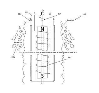
controller 210. Alternatively, the ADC 280 can be a separate component. The
ADC 280
can quantize the detected first sidebands for use by the controller 210 for
setting the
parameters of operation of the flow measurement device 200 including the
magnitude of
23
CA 02907163 2015-10-05
the time varying current applied to the electromagnet 102 and the magnitude of
the RF
current applied to the RF coil 103. The ADC 280 can quantize the detected
first
sidebands for use by the controller 210 in calculating the dwell time of spins
within the
region of interest. The controller 210 can calculate, based on the detected
first sidebands
and the parameters of operation of the flow measurement device 200, the dwell
time of
spins within the region of interest. The controller 210 can calculate, based
on the dwell
time of spins within the region of interest, the flow velocity through the
region of interest
around the flow measurement device.
[0089] The controller 210 can calculate the flow velocity based on the
received signal.
To calculate the flow velocity, controller 210 can select the Larmor frequency
to
correspond to the region of interest around the flow measurement device. The
controller
210 can adjust the magnitude of the time varying current in the electromagnet
102 to
maximize the magnitude of the first side band about the Larmor frequency of
the received
signal. The time varying solenoidal magnetic field generated by the
electromagnet 102
will cause the spins within the region of interest to emit an RF magnetic
field that can be
sinusoidal with slowly varying frequency whose Fourier transform yields a
central
Larmor frequency and discrete side bands displaced by the phase modulation
frequency.
These side bands can then be detected in the presence of the strong Larmor
excitation
frequency field by employing, for example, heterodyne frequency shift,
quadrature
detection, and cross correlation in a lock-in amplifier. The controller 210
can adjust a
magnitude of an RF current applied to the RF coil 103 to maximize the received
signal.
The magnitude of the RF current applied to the RF coil 103 can exhibit a
linear
relationship with the mean dwell time of spins in the depth of investigation.
The
controller 210 can calculate the mean dwell time of spins moving through the
region of
interest based on the magnitude of the RF current. The controller 210 can,
based on the
mean dwell time of the spins, calculate the average velocity of those spins
through the
formation 106 or linearly along the borehole 105.
[0090] Figure 3 shows a flow diagram of an example method for measuring flow
in or
around a borehole in an earth formation. The method can include inserting a
flow
measurement device into a borehole (STEP 310). The method can include
generating a
24
CA 02907163 2015-10-05
static solenoidal magnetic field (STEP 320). The method can include generating
a time
varying solenoidal magnetic field (STEP 330). The method can include
generating an RF
magnetic field transverse to the solenoidal magnetic fields (STEP 340). The
method can
include measuring a received signal induced in an RF coil (STEP 350). The
method can
include calculating the flow velocity based on the received signal (STEP 360).
[0091] The method can include inserting a flow measurement device into a
borehole
(STEP 310). The flow measurement device can be inserted into a borehole or
other
feature. The borehole can be manmade or a natural feature. The borehole can
represent a
pipe, tunnel, culvert, canal, fissure, crack, well, or any other type of
opening or conduit.
The flow measurement device can perform measurements of flow in the borehole
itself,
or in some connected feature such as a chamber, pocket, tank, aquifer, cavern,
reservoir,
or the like.
[0092] The method can include generating a static solenoidal magnetic field
(STEP 320).
The static solenoidal magnetic field Ho can be generated by any type of
electrical or
permanent magnet as described previously. The field intensity 110 of the
solenoidal
magnetic field can decrease in strength peripherally from the magnet 101. The
Larmor
frequency of particular spins in any region around the magnet 101 will depend
on the
intensity of the solenoidal magnetic field in that region (coo = yho).
[0093] The method can include generating a time varying solenoidal magnetic
field
(STEP 330). The time varying solenoidal magnetic field can be generated by
applying a
corresponding time varying current to the electromagnet 102. The strength of
the time
varying solenoidal magnetic field can vary linearly with the magnitude of the
current
applied to the electromagnet 102. The strength of the time varying magnetic
field can
decrease with distance from the electromagnet 102. The magnitude of the time
varying
current in electromagnet 102 can be adjusted to maximize the value of the
first side band
about the Larmor frequency from the received signal induced in the RF coils
103 and
104. The optimum current can be set experimentally for the given depth of
investigation.
The exact optimum current for the exact maximum signal need not be established
precisely, but in general a greater received signal can yield better
measurements.
CA 02907163 2015-10-05
[0094] The method can include generating an RF magnetic field transverse to
the
solenoidal magnetic fields (STEP 340). The RF coils 103 and 104 can generate
the RF
magnetic field. The frequency of the RF magnetic field can be set to the
Larmor coo for
the desired spins at the desired depth of investigation. The Larmor frequency
will apply
to spins within a region of interest approximating a surface of a prolate or
oblate spheroid
with a finite thickness about the magnet 101. The region of interest can have
a relatively
narrow slice thickness on the order of millimeters, depending on the gradient
of the static
magnetic field and the bandwidth of the RF magnetic field. The field intensity
110 can be
roughly constant across this region of interest. The exact shape of the region
can depend
on the shape of the magnet 101.
[0095] The method can include measuring a received signal induced in an RF
coil (STEP
350). As described above, the flow measurement device 100 can include a
combined
transmit and receive RF coil, or separate transmit and receive RF coils. To
estimate
peripheral velocity of flow, the magnitude of the current in the RF coils 103
and 104, as
applied in STEP 340, can be set for maximum received signal in STEP 350. The
time
varying solenoidal magnetic field applied at STEP 330 will cause the spins
within the
region of interest to emit an RF magnetic field that can be sinusoidal with
slowly varying
frequency whose Fourier transform yields a central Larmor frequency and
discrete side
bands displaced by the phase modulation frequency. These side bands can then
be
detected in the presence of the strong Larmor excitation frequency field by
employing,
for example, heterodyne frequency shift, quadrature detection, and cross
correlation in a
lock-in amplifier as described above.
[0096] The method can include calculating the flow velocity based on the
received signal
(STEP 360). To estimate peripheral velocity of flow, the magnitude of the
current in the
RF coils 103 and 104 applied in STEP 340 can be set to maximize the magnitude
of the
first sideband about the Larmor frequency in the received signal. The
magnitude of the
RF current can display a linear relationship with the mean dwell time of the
spins in the
depth of investigation. The mean dwell time of spins moving through the region
of
interest can be calculated based on the magnitude of the RF current. The
average
26
CA 02907163 2015-10-05
velocity of those spins either through the formation 106 or linearly along the
borehole
105 can be calculated from the mean dwell time of the spins.
[0097] The foregoing disclosure is equally applicable to nuclear and electron
magnetic
resonance. Furthermore, the measurement of velocity by the device described in
this
disclosure is applicable not only to liquid or gas, but to flow of other fluid
materials, such
as mixtures, slurries, aggregates, blowing particles, viscous plastics as well
as to the flow
of solid materials.
[0098] Preferred embodiments of the invention have now been described. It will
be
appreciated by those skilled in the art that such embodiments are intended to
exemplify
the invention. Various other embodiments of the invention will be apparent,
which fall
within the spirit and scope of the invention.
27