Note: Descriptions are shown in the official language in which they were submitted.
VEHICLE CONSUMPTION MONITORING SYSTEM AND METHOD
FIELD
[0002] The subject matter described herein relates to vehicles that
consume fuels
and/or energy to propel the vehicles.
BACKGROUND
[0003] Various types of vehicles consume fuels and/or energy to power the
vehicles.
For example, fuel gas (e.g., diesel and non-diesel fuels), electric current,
oil, coal, natural
gas, wind power, solar power, or the like, may be used to power the vehicles.
The
vehicles may power themselves to propel the vehicles using these fuels and/or
energy.
[0004] The consumption of the fuels and/or energy may not be equivalent
across
different vehicles and/or operators of the vehicles. For example, due to
differences in the
way operators control throttles and/or brakes of the vehicles, different
vehicles of the
same type of vehicle (e.g., different ones of the same make and/or model of a
vehicle)
that are operated by different drivers may consume different amounts of fuel
and/or
energy to propel the vehicles over the same or substantially similar routes.
[0005] Simply measuring how much fuel and/or energy is consumed by
different
operators controlling the vehicles may not provide insight into how the
operators can
control the vehicles more efficiently. Merely comparing how much fuel is
consumed by
one operator versus another operator may not accurately reflect if the driving
habits of
one operator are more or less efficient in terms of the fuel and/or energy
consumed than
another operator.
1
Date Recue/Received date 2020-04-08
CA 02907387 2015-10-08
278952
[0006] The amount of fuel and/or energy consumed may be based on a variety
of
other factors that are not readily apparent. For example, calculating a
distance traveled
by a vehicle per unit of fuel and/or energy (e.g., miles per gallon,
kilometers per liter, or
the like) may not accurately reflect how efficiently different operators
control the
vehicles because the amount of fuel and/or energy that is consumed can
significantly
increase during travel over inclined segments of a route, even for more
efficient
operators.
[0007] Being able to directly compare how efficiently different operators
control
vehicles may be useful in examining the operators to find more efficient ways
to control
the vehicles, in identifying which vehicles operate more efficiently than
other vehicles, or
the like.
BRIEF DESCRIPTION
[0008] In one embodiment, a monitoring system includes a control system
configured
to determine a consumption metric representative of one or more of an amount
of fuel
consumed or an amount of energy consumed by a vehicle during travel over a
route. The
consumption metric is independent of one or more of vehicle load or elevation
change
over the route.
[0009] In another embodiment, another monitoring system includes a control
system
configured to determine a route condition metric representative of a condition
of a route
traveled upon by a vehicle. The route condition metric is based on a
comparison between
an actual grade of the route at one or more locations along the route and an
estimated
grade of the route at the one or more locations.
[0010] In another embodiment, a method (e.g., for monitoring a vehicle)
includes
determining a consumption metric representative of one or more of an amount of
fuel
consumed or an amount of energy consumed by a vehicle during travel over a
route. The
consumption metric is independent of one or more of vehicle load or elevation
change
over the route.
2
CA 02907387 2015-10-08
278952
[0011] In another embodiment, another method (e.g., for monitoring a route)
includes
determining a route condition metric representative of a condition of a route
traveled
upon by a vehicle. The route condition metric can be based on a comparison
between an
actual grade of the route at one or more locations along the route and an
estimated grade
of the route at the one or more locations.
BRIEF DESCRIPTION OF THE DRAWINGS
[0012] Reference is made to the accompanying drawings in which particular
embodiments and further benefits of the invention are illustrated as described
in more
detail in the description below, in which:
[0013] Figure 1 is a schematic illustration of a vehicle having a vehicle
consumption
monitoring system according to one embodiment;
[0014] Figure 2 illustrates a grade profile for a trip of the vehicle shown
in Figure 1
according to one example;
[0015] Figure 3 illustrates a different grade profile for a trip of the
vehicle shown in
Figure 1 according to one example;
[0016] Figure 4 illustrates a flowchart of one embodiment of a method for
monitoring
consumption of fuel and/or energy by a vehicle; and
[0017] Figure 5 illustrates a flowchart of one embodiment of a method for
monitoring
conditions of a route being traveled by one or more vehicles.
DETAILED DESCRIPTION
[0018] One or more embodiments of the subject matter described herein
provide
systems and methods that determine consumption metrics representative of how
much
fuel and/or energy is consumed by vehicles. The consumption metrics can
represent the
consumed fuel and/or energy independent of vehicle load and/or elevation
change over
the course of trips traveled by the vehicles. The consumption metrics may be
3
CA 02907387 2015-10-08
278952
independent of the vehicle load and/or elevation change over the trips in that
the
consumption metrics do not change for different vehicle loads and/or elevation
changes
for a vehicle traveling a trip. For example, if a vehicle is operated in the
same manner
(e.g., the same throttle and/or brake settings are used at the same locations)
along the
same route from the same origin location to the same destination location for
first and
second trips, but the vehicle load differs for the first trip versus the
second trip, then the
consumption metrics may be the same or substantially the same (e.g., within a
designated
range of each other, such as 1%, 3%, 5%, or the like) for the first and second
trips. As
another example, if the vehicle is operated in the same manner (e.g., the same
throttle
and/or brake settings are used at the same locations) along different routes
that cause the
vehicle to experience different changes in elevation between origin and
destination
locations for third and fourth trips, then the consumption metrics may be the
same or
substantially the same. Determining the consumption metrics to be independent
of
vehicle loads and/or elevation changes can allow for the consumption metrics
for
different operators of the vehicles, different vehicles, different operational
conditions of
the vehicles, and the like, to be more easily compared to identify which
vehicles,
operators, and/or operational conditions are more efficient and/or to allow
operators to
more easily learn how to operate the vehicles more efficiently. Optionally,
one or more
route metrics can be determined. The route metrics can represent conditions of
the routes
being traveled upon by the vehicles. The consumption metrics and/or route
metrics can
be displayed to operators of the vehicles and/or communicated to a location
that is off-
board the vehicles (e.g., a dispatch center) for review by the operator and/or
others at the
off-board loCation.
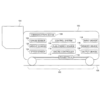
[0019] Figure 1 is a
schematic illustration of a vehicle 100 having a vehicle
consumption monitoring system 102 according to one embodiment. The monitoring
system determines consumption metrics and/or route metrics described herein to
assist
the operator of the vehicle 100 and/or others to analyze performance and/or
operation of
the vehicle 100. The vehicle 100 may be an off-highway vehicle, such as a
mining
vehicle or other vehicle that is not designed and/or not legally permitted to
travel on
4
CA 02907387 2015-10-08
278952
public roadways. For example, the vehicle 100 may represent a load-haul-dump
(hereinafter "LHD") type vehicle having a bucket 104 or other apparatus for
carrying
cargo. Alternatively, the vehicle 100 may be another type of mining vehicle.
In another
embodiment, the vehicle 100 is another type of vehicle, such as a rail vehicle
(e.g., a
locomotive), an automobile, a marine vessel, an airplane or other vehicle
capable of
flight, or the like. Optionally, the vehicle 100 can represent a vehicle
consist, such as a
group of two or more vehicles that are mechanically and/or logically coupled
with each
other to travel along a route 106 as a unit. Such a vehicle consist can
include several
vehicles connected by couplers with one or more of the vehicles 100 propelling
the
vehicle consist, or several vehicles that are not mechanically coupled with
each other, but
that communicate with each other to coordinate movements of each other such
that the
vehicle consist travels as a unit along the route 104. The components of the
vehicle 100
and/or monitoring system 102 can be operably connected with each other by one
or more
wired and/or wireless connections. For example, the components described
herein can be
connected by wires, cables, busses, wireless network channels, or the like,
for
communication of data and/or other signals there between.
[0020] The monitoring system 102 is shown as being entirely disposed
onboard the
vehicle 100. Optionally, one or more components of the monitoring system 102
may be
disposed elsewhere, such as at an off-board location (e.g., a dispatch
center), onboard
another vehicle in the same vehicle consist as the vehicle 100, in another
vehicle that is
not in the same vehicle consist as the vehicle 100, or the like.
[0021] The monitoring system 102 includes a control system 108 that
represents
hardware circuits or circuitry that includes and/or is connected with one or
more
processors (e.g., electronic logic-based devices, such as microprocessors,
computers,
controllers, engine control units, or the like). The processors can operate
based on
instructions stored on a tangible and non-transitory computer readable memory
device
116, such as a computer hard drive, optical drive, flash drive, solid state
drive, or the like.
These instructions can direct the processors to carry out one or more
operations described
herein. For example, a single processor can perform all of the operations
described
CA 02907387 2015-10-08
278952
herein, two or more processors may perform different operations, and/or two or
more
processors may perform one or more of the same operations.
[0022] The control system 108 can calculate consumption metrics for
operators of the
vehicle 100. The consumption metrics can be operator dependent in that
different
consumption metrics can be calculated for different operators operating the
same vehicle
100 over the same trip carrying the same load, due to the different ways in
which the
operators control the vehicle 100. In one aspect. a per-operator consumption
metric can
represent or be calculated as the fuel and/or energy consumed per unit of an
energy
required for a trip or a segment of the trip. For example, the consumption
metric may be
calculated as the fuel and/or energy actually consumed by the vehicle 100 from
a first
location to a different, second location along the route 106, divided by an
amount of
energy that is calculated as being required to propel the vehicle 100 from the
first location
to the second location:
C, = --P (Equation No. 1)
where C, represents the consumption metric for the i operator of the vehicle
100, F
represents the actual amount of fuel and/or energy consumed by the vehicle 100
in
moving from a first location to a second location, and E represents the amount
of energy
that is calculated as being required by the vehicle 100 to move from the first
location to
the second location.
[0023] The actual amount of fuel and/or energy consumed by the vehicle 100
(F) can
be determined from data provided by an engine controller 110 of the vehicle
100. The
engine controller 110 can represent an electronic control unit, such as an
engine control
unit (ECU), powertrain control module (PCM), or the like, that controls one or
more
engines of the vehicle 100 and/or monitors operation of the one or more
engines. A
powertrain 112 of the vehicle 100 represents the one or more engines of the
vehicle 100,
as well as motors, shafts, gears, axles, or the like, that translate movement
(e.g., rotation)
by the engines into propulsion of the vehicle 100.
CA 02907387 2015-10-08
278952
[0024] The engine controller 110 also can include and/or represent a supply
sensor
that generates data representative of how much fuel and/or energy is supplied
to the
engine of the vehicle 100 from a fuel and/or energy source 114 ("Fuel/Energy
Source" in
Figure 1). For example, the engine controller 110 can include a mass flow
sensor that
generates data representative of how much fuel is supplied to the engine, an
ammeter that
generates data representative of how much electric current is supplied to the
motors of the
vehicle and/or generated by the engine, or the like. The source 114 can
represent one or
more tanks holding fuel and/or batteries, capacitors, or the like, storing
electric energy for
powering the vehicle 100.
[0025] The control system 108 can monitor this data from the engine
controller 110
to determine how much fuel and/or energy is actually consumed by the vehicle
100 (F).
Optionally, the control system 108 can calculate the amount of fuel and/or
energy that is
actually consumed (F) based on one or more efficiency estimates and power
generated by
the powertrain 112. For example, the control system 108 can estimate the
amount of fuel
and/or energy that is actually consumed (F) based on the amounts of power
generated by
the powertrain 112 and a designated efficiency rate representative of how
efficiently the
powertrain 112 consumes fuel and/or energy at the different power outputs of
the
powertrain 112.
[0026] The energy required for moving the vehicle 100 (E) can be calculated
by the
control system 108. In one embodiment, the required energy can be estimated
based on
an unloaded weight of the vehicle 100, a weight of a vehicle load, grades of
segments of
the route 106 between the first and second locations, a moving resistance of
the vehicle
100, and a distance along the route 106 from the first location to the second
location. The
energy (E) can be based on these factors such that, an increase in the
unloaded weight, an
increase in the weight of the vehicle load, inclined grades, an increase in
the moving
resistance, and/or an increase in the distance traveled can cause the energy
(E) to
increase, while a decrease in the unloaded weight, a decrease in the weight of
the vehicle
load, declined grades, a decrease in the moving resistance, and/or a decrease
in the
distance traveled can cause the energy (F) to decrease.
7
CA 02907387 2015-10-08
278952
[0027] The unloaded weight of the vehicle 100 can be a designated weight of
the
vehicle 100 without cargo or materials being carried by the vehicle 100. This
weight can
be programmed into the memory device 116 and/or the control system 108.
Optionally,
this weight can be input into the control system 108 and/or memory device 116
using an
input device 118 of the vehicle 100. The input device 118 can represent one or
more
assemblies used to receive information from an operator, such as a keypad,
electronic
mouse, stylus, touchscreen, microphone, pedal, throttle lever, button, or the
like. The
control system 108 optionally may obtain the weight from the memory device
116.
[0028] The weight of the vehicle load can be the weight of the cargo and/or
materials
being carried by the vehicle 100. This weight can be in addition to the
unloaded weight
of the vehicle 100. For example, a total weight of the vehicle 100 can include
the weight
of the vehicle load and the unloaded weight of the vehicle 100. The weight of
the vehicle
load can be input using the input device 118 and/or can be obtained from data
generated
by a weight sensor 120 (e.g., a scale) that represents the weight of the cargo
and/or
materials being carried by the vehicle 100.
[0029] The grades of segments of the route 106 between the first and second
locations represent the amount of incline and/or decline of different segments
of the route
106. The grades can be determined based on data generated by a grade sensor
122, such
as an inclinometer, accelerometer, etc., may be input using the input device
118, and/or
may be obtained from a database stored in the memory device 116. For example,
the
layout of the mute 106 (e.g., glades, distances, curvatures, or the like) may
be stored in
the memory device 116.
[0030] The moving resistance of the vehicle 100 can represent forces that
resist
movement of the vehicle 100 along the route 106. This resistance can represent
forces
resisting motion of the vehicle 100 when the vehicle 100 moves along the route
106, such
as rolling resistance, drag, air and/or water currents, or the like. The
moving resistance
can be measured or estimated by the control system 108 based on how much power
is
generated by the powertrain 112 and how fast the vehicle 100 moves. The moving
speed
8
CA 02907387 2015-10-08
278952
of the vehicle 100 can be determined from data generated by a speed sensor
124, such as
a tachometer, global positioning system receiver, cellular triangulation
system, or other
device. Optionally, the moving resistance can have a designated value that is
stored in
the memory device 116 and/or is input via the input device 118.
[0031] The distance traveled by the vehicle 100 can be determined by the
control
system 108, such as by monitoring how fast the vehicle 100 travels and for how
long; by
examining data generated by a global positioning system receiver, cellular
triangulation
system, or the like; and/or by receiving the distance from the memory device
116 and/or
the input device 118.
[0032] The consumption metric can be calculated using one or more of these
factors
to represent how efficiently the operator controls the vehicle 100 from the
first location to
the second location. Basing the consumption metric on the fuel and/or energy
consumed
per energy required to travel (E) instead of the fuel and/or energy consumed
per just the
distance traveled can allow for the consumption metrics for different trips of
the vehicle
100 or vehicles 100 to be compared. For example, different trips may have
different
grade profiles, which can significantly impact the rate of fuel and/or energy
consumption,
even though the distances traveled by the vehicle 100 or vehicles 100 in the
different trips
may be the same or substantially the same. Additionally, the different grade
profiles can
significantly impact the rate of fuel and/or energy consumption for trips
having very
different distances.
[0033] Figures 2 and 3 illustrate different grade profiles 200, 300 for
trips of the
vehicle 100 according to one example. The grade profiles 200, 300 are shown
alongside
horizontal axes 202 representative of distance along a route 106 (shown in
Figure 1) and
vertical axes 204 representative of elevation. The grade profiles 200, 300
represent the
grades of the route 106 encountered by vehicles 100 traveling from origin
locations 206,
306 to corresponding final locations 208, 308 of trips or hauls of the
vehicles 100.
Distances 210 along the route 106 from the origin locations 206, 306 to the
final locations
208, 308 may be the same or substantially the same.
9
CA 02907387 2015-10-08
278952
[0034] During travel along the route 106 according to the different grade
profiles 200,
300, the vehicle 100 traveling along the grade profile 200 may consume more
fuel and/or
energy than the vehicle 100 traveling along the grade profile 300. For
example,
generating sufficient torque or tractive effort to propel the vehicle 100 up
segments 212
of inclined grades in the grade profile 200 may require more fuel and/or
energy to be
consumed by the powertrain 112 relative to the vehicle 100 traveling along the
grade
profile 300. Differences in the consumption metrics for the vehicles 100
traveling along
the grade profiles 200, 300 can be due to differences in the ways in which
operators of
the vehicles 100 control the vehicles 100. For example, a first operator may
drive a first
vehicle 100 over the grade profile 200 and a second operator may drive a
second vehicle
100 over the grade profile 300. The first and second vehicles 100 may have
different
vehicle loads. The second operator may change throttle positions more
frequently and/or
use larger changes in throttle positions, thereby causing the second vehicle
100 to
accelerate and/or decelerate along the grade profile 300 more rapidly and/or
by greater
amounts relative to the first operator.
[0035] As a result, the consumption metric for the second operator may be
larger than
the consumption metric for the first operator due to the second operator
driving less
efficiently than the first operator, even though the first operator controls
the first vehicle
100 over larger inclines in the route 106 and/or the first vehicle 100 is
carrying a heavier
load. The consumption metric of the first operator may be smaller than the
consumption
metric of the second operator due to the larger and/or more frequent changes
in throttle
positions by the second operator. For example, the amount of energy that is
estimated as
being required for the first vehicle 100 to travel over the grade profile 200
(e.g., E) may
be larger than the amount of energy that is estimated as being required for
the second
vehicle 100 to travel over the grade profile 300 (e.g., E) due to the grades
of the segments
212 in the grade profile 200 being larger than the grades of the grade profile
300.
Optionally, the unloaded weight of the first vehicle 100, the vehicle load
carried by the
first vehicle 100, the moving resistance of the first vehicle 100, and/or the
distance over
the grade profile 200 may be larger or longer than that for the second vehicle
100.
CA 02907387 2015-10-08
278952
[0036] The first operator may cause the first vehicle 100 to consume more
fuel and/or
energy than the second operator causes the second vehicle 100 to consume
during travel
over the respective grade profiles 200, 300, but, because the needed energy
(E) that is
estimated for the first vehicle 100 is larger than the needed energy (E)
estimated for the
second vehicle 100, the consumption metric of the second operator may be
larger than the
consumption metric of the first operator. This may be due to the more
inefficient manner
in which the second operator controls the second vehicle 100 relative to the
first operator
and the first vehicle 100.
[0037] Returning to the description of the vehicle 100 and the monitoring
system 102
shown in Figure 1, the vehicle 100 and/or monitoring system 102 may include an
output
device 126, such as an electronic display device (e.g., computer monitor,
touchscreen,
etc.), a speaker, or the like. The control system 108 may communicate the
consumption
metric calculated for an operator of the vehicle 100 to the output device 126,
and the
output device 126 may present (e.g., display or otherwise communicate to the
operator)
the consumption metric to the operator. In one aspect, the consumption metric
is
calculated and/or presented to the operator following completion of a trip of
the vehicle
100 (e.g., traveling from an origin location to a destination location).
Optionally, the
consumption metric may additionally or alternatively be calculated and/or
presented to
the operator at designated time intervals, such as the end of a working shift
of the
operator, every hour, or the like. Additionally or alternatively, the
consumption metric
may be calculated and/or presented as the operator is driving the vehicle 100.
The output
device 126 can present the consumption metric along with the actual amount of
fuel
and/or energy consumed by the operator.
[0038] The vehicle 100 and/or monitoring system 102 may include a
communication
device 128. The communication device 128 includes or represents hardware
and/or
software that are used to communicate with off-board locations, such as other
vehicles
100, a dispatch center, or the like. The communication device 128 may include
an
antenna, a transceiver, and/or associated circuitry for wirelessly
communicating (e.g.,
communicating and/or receiving) information described herein, such as
consumption
11
CA 02907387 2015-10-08
278952
metrics, the actual amount of fuel and/or energy consumed by a vehicle 100,
efficiency
estimates, power generated by a powertrain 112, an unloaded weight of a
vehicle 100, a
weight of a vehicle load, grades of segments of a route, a grade profile, a
moving
resistance of a vehicle, a distance to be traveled or that has been traveled
by a vehicle
100, or the like. Optionally, the communication device 128 can include and/or
represent
a location determining device, such as a global positioning system receiver, a
cellular
triangulation system, or the like.
[0039] In one aspect, the control system 108 may determine one or more
comparison
metrics to be presented to the operator via the output device 126 and/or
communicated to
one or more off-board locations. The comparison metrics can include an
average,
median, or other statistical analysis of other consumption metrics. For
example, several
consumption metrics calculated for an operator over several trips, several
working shifts,
several days, several weeks, several months, or the like, may be stored in the
memory
device 116 and/or in a memory device disposed off-board the vehicle 100. An
average or
median of these consumption metrics can be calculated as an operator-specific
consumption metric. This operator-specific consumption metric can be saved to
monitor
the operator over time and/or presented on the output device 126 so that the
operator can
compare a current consumption metric with the average or median consumption
metric of
the operator. The operator can determine based on a comparison of these
metrics of the
operator is controlling the vehicle 100 more or less efficiently than prior
trips of the
operator.
[0040] As another example, the consumption metrics calculated for several
different
operators controlling the same vehicle 100 at different times (e.g., during
different trips)
may be used to calculate a vehicle-specific consumption metric. The vehicle-
specific
consumption metric may be an average or median of the consumption metrics
calculated
for different trips of the same vehicle 100, regardless of which operators are
driving the
vehicle 100 during the different trips. The vehicle-specific consumption
metric may be
monitored by the control system 108 and/or an off-board location (e.g., a
dispatch center)
to identify trends in the metric that may be indicative of an impending
mechanical fault or
12
CA 02907387 2015-10-08
278952
failure of the vehicle 100. For example, if the vehicle-specific consumption
metric is
increasing over time and/or increasing over several different operators
driving the vehicle
100, then the increasing metric may indicate that the vehicle 100 is consuming
more and
more fuel and/or energy, and therefore may have an impeding mechanical fault
or failure.
The control system 108 and/or off-board location may then automatically (e.g.,
without
operator intervention) generate warning signals presented on the output device
126 and/or
communicated to a repair facility to warn the operator and/or schedule
inspection, repair,
and/or maintenance of the vehicle 100.
[0041] As another example, the consumption metrics calculated for several
vehicles
100 operating in a same location may he used to calculate a location-specific
consumption metric. For example, consumption metrics may be calculated for
mining
vehicles operating in the same mine. As another example, consumption metrics
for
vehicles 100 operating during a designated time period (e.g., a day, a week, a
month, a
year, or the like) in a designated location or area (e.g., the same city,
county, state,
country, or the like). An average or median of these consumption metrics may
be
calculated as a location-specific consumption metric. The location-specific
consumption
metric may be displayed to an operator and/or compared to the consumption
metric of the
operator by the control system 108 to determine how efficiently the operator
is
controlling the vehicle 100 relative to other operators in the same location.
[0042] As another example, the consumption metrics calculated for several
vehicles
100 in a fleet of the vehicles 100 may be used to calculate a fleet-wide
consumption
metric. The vehicles 100 that are included in a fleet may be those vehicles
100 that are
operating under the direction of a manager or other single director of
operations, that are
moving together (e.g., at the same time), that are engaged in the same
activity (e.g.,
mining the same mine), and/or that are under the same ownership. The fleet-
wide
consumption metric may be displayed to an operator and/or compared to the
consumption
metric of the operator by the control system 108 to determine how efficiently
the operator
is controlling the vehicle 100 relative to other operators in the same fleet.
13
CA 02907387 2015-10-08
278952
[0043] The control system 108 optionally may calculate different
consumption
metrics for different operational settings of the vehicle 100. These
consumption metrics
can be referred to as operational mode-specific consumption metrics. As one
example,
different consumption metrics may be calculated for different throttle
positions, power
outputs, speeds, or the like, of the vehicle 100. During time periods that the
operator
controls the vehicle 100 at a first throttle setting (e.g., a first pedal
position, first throttle
lever position, etc.), a first power output (e.g., horsepower), a first speed,
or the like, the
control system 108 may calculate a first consumption metric. During different
time
periods that the operator controls the vehicle 100 at a different, second
throttle setting, a
different, second power output, a different, second speed, or the like, the
control system
108 may calculate a second consumption metric, and so on. As another example,
different consumption metrics may be calculated for different operational
modes of the
vehicle 100. For example, during time periods that the operator controls the
vehicle 100
to accelerate, the control system 108 may calculate a first consumption
metric. During
other, different time periods that the operator controls the vehicle 100 to
decelerate, the
control system 108 may calculate a second consumption metric. During other,
different
time periods that the operator controls the vehicle 100 to maintain a speed
(e.g., coast,
such as by not changing speed by more than a designated threshold of 1%, 3%,
5%, or the
like), the control system 108 may calculate a third consumption metric. The
different
consumption metrics can be displayed to the operator on the output device 126,
such as
by displaying the operational mode-specific consumption metrics corresponding
to a
current operational mode of the vehicle 100 (e.g., throttle positions,
accelerating,
decelerating, coasting, or the like) can be displayed during the corresponding
current
operational mode.
[0044] Additionally or alternatively, different consumption metrics can be
determined
for different grades of the route 106. These consumption metrics can be
referred to as
grade-specific consumption metrics. For example, during travel over different
segments
of the route 106 having the same or similar grade (e.g., the angles of
inclination or
declination are within a designated range of each other, such as 1%, 3%, 5%,
10%, or
14
CA 02907387 2015-10-08
278952
another value), an average, median, or the like, of the consumption metrics
may be
calculated as the grade-specific consumption metric for those segments. During
travel
over other segments of the route 106 having the same or similar grade, an
average,
median, or the like, of the consumption metrics may be calculated as the grade-
specific
consumption metric for those segments, and so on.
[0045] Additionally or alternatively, different consumption metrics can be
determined
for time periods when the vehicle 100 is loaded or unloaded with cargo, and/or
for
different weights of the cargo. These consumption metrics can be referred to
as vehicle
loading-specific consumption metrics. For example, during travel when the
vehicle 100
has a loaded weight within a first range of weight (e.g., less than five
hundred kilograms),
an average, median, or the like, of the consumption metrics may be calculated
as the
vehicle loading-specific consumption metric for that amount of load. During
travel when
the vehicle 100 has a loaded weight within a second range of weight (e.g., at
least five
hundred kilograms but less than one thousand kilograms), an average, median,
or the like,
of the consumption metrics may be calculated as the vehicle loading-specific
consumption metric for that amount of load, and so on. A consumption metric
also may
be calculated for when the vehicle 100 is not carrying any load.
[0046] As one example, different consumption metrics may be calculated for
different throttle positions of the vehicle 100. During time periods that the
operator
controls the vehicle 100 at a first throttle setting (e.g., a first pedal
position, first throttle
lever position, etc.), the control system 108 may calculate a first
consumption metric,
during different time periods that the operator controls the vehicle 100 at a
different,
second throttle setting, the control system 108 may calculate a second
consumption
metric, and so on. As another example, different consumption metrics may be
calculated
for different operational modes of the vehicle 100. For example, during time
periods that
the operator controls the vehicle 100 to accelerate, the control system 108
may calculate a
first consumption metric. During other, different time periods that the
operator controls
the vehicle 100 to decelerate, the control system 108 may calculate a second
consumption
metric. During other, different time periods that the operator controls the
vehicle 100 to
CA 02907387 2015-10-08
278952
maintain a speed (e.g., coast, such as by not changing speed by more than a
designated
threshold of 1%, 3%, 5%, or the like), the control system 108 may calculate a
third
consumption metric. The different consumption metrics can be displayed to the
operator
on the output device 126, such as by displaying the operational mode-specific
consumption metrics corresponding to a current operational mode of the vehicle
100
(e.g., throttle positions, accelerating, decelerating, coasting, or the like)
can be displayed
during the corresponding current operational mode.
[0047] The consumption metrics may be monitored by one or more off-board
locations (e.g., a dispatch center or facility) to monitor historical trends
in the
consumption metrics for different operators, different vehicles, and the like.
Based on
this data, poor performing operators, vehicles 100, or the like, can be
identified and
remedied by instruction, repair, or the like. For example, poor performing
operators may
be identified and the manner in which the operators control vehicles 100
examined in
order to instruct the operators how to more efficiently operate the vehicles
100. As
another example, vehicles 100 with poor consumption metrics may be scheduled
for
inspection, repair, and/or maintenance. As another example, fleet-wide
consumption
metrics may be examined to determine how to improve efficiency across the
fleet.
Consumption metrics also may be examined to determine future areas for
improved
efficiencies.
[0048] The condition of the route 106 being traveled upon by the vehicle
100 also can
impact the efficiency at which the vehicle 100 consumes fuel and/or energy.
For
example, poor road conditions can cause increased fuel and/or energy
consumption due to
increased torque being needed to propel the vehicle 100 over the route 106. In
addition
or as an alternate to determining the consumption metrics, the control system
108 can
determine a route condition metric. The route condition metric can represent
the
condition of the route 106, such as a quantifiable value representative of how
close or far
the actual condition of the route 106 is to an ideal condition of the route
106. In one
embodiment, the route condition metric may be based on a comparison between an
16
CA 02907387 2015-10-08
278952
estimated grade of the route 106 and an actual grade of the route 106. For
example, the
route condition metric may be calculated as:
Ge
R ¨ (Equation No. 2)
where R represents the route condition metric for the route 106 at one or more
locations,
Ge represents an estimated grade of the route 106 at the one or more
locations, and Gm
represents the actual or measured grade of the route 106 at the one or more
locations.
[0049] The estimated grade of the route 106 (GO may be obtained by the
control
system 108. The control system 108 can calculate the estimated grade based on
the
vehicle load, the unloaded vehicle weight, the power generated by the
powertrain 112
(e.g., torque), and/or the speed of the vehicle 100. For example, the
estimated grade may
be larger for heavier vehicle loads, heavier unloaded vehicle weights,
increased torque
generated by the powertrain 112, and/or decreased speeds of the vehicle 100,
and the
estimated grade may be smaller for lighter vehicle loads, lighter unloaded
vehicle
weights, decreased torque generated by the powertrain 112, and/or increased
speeds of
the vehicle 100. The actual or measured grade of the route 106 (Gm) may be
obtained
from the data generated by the grade sensor 122 and/or from a database of
grades
recorded in the memory device 116.
[0050] In one aspect, the control system 108 may apply a filter to one or
more of the
route condition metric, the estimated grade of the route 106 (GO, and/or the
actual or
measured grade of the route 106 (Gm) to remove the impact of noise on the
calculation of
the route condition metric. Poor conditions of the route 106 can cause the
power
generated by the powertrain 112 (e.g., torque), the speed of the vehicle 100,
and/or the
measured grade of the route 106 to temporarily increase or decrease during
relatively
short time periods, such as when wheels of the vehicle 100 slip relative to
the route 106.
In order to eliminate or reduce the impact of these transient effects on the
estimated grade
of the route 106 (GO and/or the actual or measured grade of the route 106
(Gm), a low
pass filter may be applied to the estimated grade of the route 106 (GO and/or
the actual or
17
CA 02907387 2015-10-08
278952
measured grade of the route 106 (Gm). Such a filter may remove changes in the
estimated
grade of the route 106 (Ge) and/or the actual or measured grade of the route
106 (Gm) that
occur (e.g., increase and then decrease, or decrease and then increase) within
a designated
time period, such as within one second, three seconds, five seconds, or the
like. As a
result, noise in the estimated grade of the route 106 (GO and/or the actual or
measured
grade of the route 106 (Gm) is eliminated from the calculation of the route
condition
metric.
[0051] The route
condition metric can be presented to the operator via the output
device 126 and/or communicated to an off-board location via the communication
device
128. The route condition metric can represent the condition of the route 106.
For
example, larger route condition metrics may indicate that the powertrain 112
of the
vehicle 100 is using more power (and therefore fuel and/or energy) to propel
the vehicle
100 than should be necessary over the actual grade of the route 106,
potentially due to
poorer conditions of the route 106 (relative to smaller route condition
metrics).
Responsive to the route condition metric exceeding a designated threshold
(e.g., a value
of one, 1.25, 1.5, two, or another value), a warning signal may be
automatically
communicated to the operator and/or an off-board location. This warning signal
may
cause other vehicles 100 to change operation (e.g., use lower torques by
automatically
restricting the range of throttle settings that the vehicles can use), to
cause a dispatch
center to change schedules and/or routes of the vehicles 100 to avoid the
routes 106 with
poorer conditions (e.g., by automatically changing schedules of the vehicles
to avoid
these routes), to automatically change signals that direct which routes 106
the vehicles
100 are to take to avoid the routes 106 with poorer conditions, or the like.
In one aspect,
the route condition metric can be used to identify when to perform inspection,
maintenance, and/or repair of a route 106, such as when the route condition
metric
exceeds the designated threshold and/or when the route condition metric
continues to
increase over a designated period of time (e.g., one or more days, weeks,
months, or the
like, such as a time period that is longer than an adverse weather condition
or season
associated with adverse weather conditions, like winter or spring). Responsive
to the
18
CA 02907387 2015-10-08
278952
route condition metric exceeding the designated threshold, a dispatch facility
may
automatically communicate an instruction to a repair vehicle to travel to the
location of
the route associated with the route condition metric to inspect and/or repair
the vehicle.
[0052] Figure 4 illustrates a flowchart of one embodiment of a method 400
for
monitoring consumption of fuel and/or energy by a vehicle. The method 400 may
be
performed by the monitoring system 122 to monitor the efficiency in which a
vehicle 100
is operated. At 402, an amount of energy required for moving the vehicle 100
over an
upcoming segment of a route 106 (e.g., from a first location to a second
location) is
determined. As described above, this energy can be calculated based on an
unloaded
weight of the vehicle 100, a weight of a vehicle load, grades of segments of
the route 106
between the first and second locations, a moving resistance of the vehicle
100, and a
distance along the route 106 from the first location to the second location.
[0053] At 404, an amount of fuel and/or energy that is actually consumed by
the
vehicle 100 for movement over the upcoming segment of the route 106 is
determined.
For example, the volume of fuel and/or amount of electric energy that is used
to power
the vehicle 100 during travel over the upcoming segment is measured or
estimated. At
406, a consumption metric is determined based on the needed amount of energy
and the
amount of fuel and/or energy that is actually consumed. The consumption metric
may be
expressed in terms of gallons, liters, amps, watts, or the like, per Joule or
other unit of
energy. Optionally, the consumption metric may be determined based on one or
more
other consumption metrics, operational settings or modes, grades, operators,
or the like,
as described herein.
[0054] At 408, the consumption metric is presented to an operator of the
vehicle 100
and/or to an off-board location. For example, the consumption metric may be
shown on
the output device 126 to the operator and/or communicated via wireless
transmission
and/or broadcast to a dispatch facility. At 410, a determination is made as to
whether the
consumption metric indicates that one or more remedial actions need to be
taken. For
example, consumption metrics that exceed one or more thresholds (e.g., one,
1.5, two,
19
CA 02907387 2015-10-08
278952
2.5, or the like), may indicate that the vehicle 100 is consuming more fuel
and/or energy
than is needed and that action needs to be taken to reduce the amount of fuel
and/or
energy being wasted. If the consumption metric indicates that remedial action
needs to
be taken, then flow of the method 400 can proceed to 412. Otherwise, flow of
the
method 400 can return to 402.
[0055] At 412, one or more remedial actions may be taken. For example, the
control
system 108 may automatically implement restrictions on how frequently and/or
how
much throttle settings, speeds, and/or power outputs of the vehicle 100 can
change in
order to prevent the operator from accelerating at too great of a rate
responsive to the
consumption metric exceeding a designated threshold. As another example, the
control
system 108 and/or off-board location may then automatically generate warning
signals
presented on the output device 126 and/or communicated to a repair facility to
warn the
operator and/or schedule inspection, repair, and/or maintenance of the vehicle
100
responsive to the consumption metric exceeding a designated threshold. As
another
example, the consumption metric may indicate that travel over a certain grade
causes an
increase in the consumption metric. The control system 108 and/or dispatch
center may
prevent the vehicle 100 from traveling over that grade and/or limiting
operations of the
vehicle 100 to reduce the consumption metric over the grade. As another
example, the
consumption metric may indicate that certain cargo and/or load weights causes
the
vehicle 100 to have an increased consumption metric relative to other cargos
and/or load
weights. The remedial action may involve scheduling or otherwise causing the
vehicle
100 to carry one or more cargos or load weights associated with the lower
consumption
metric and/or preventing the vehicle 100 from carrying the cargo and/or load
weight
associated with the larger consumption metric. Flow of the method 400
optionally may
then return to 402.
[0056] Figure 5 illustrates a flowchart of one embodiment of a method 500
for
monitoring conditions of a route being traveled by one or more vehicles. The
method
500 may be performed by the monitoring system 122 to monitor the conditions of
the
route 106. At 502, an estimated grade of the route 106 at one or more
locations is
CA 02907387 2015-10-08
278952
determined. The estimated grade of the route 106 may be calculated based on
the vehicle
load, the unloaded vehicle weight, the power generated by the powertrain 112
(e.g.,
torque), and/or the speed of the vehicle 100, as described above. At 504, the
actual grade
of the route 106 is determined at the one or more locations. For example, the
actual grade
may be measured from the data generated by the grade sensor 122 and/or from a
database
of grades recorded in the memory device 116. For example, the current location
of the
vehicle 100 can be compared with locations along the route 106 that are stored
in the
memory device 116 with associated grades in order to determine the actual
grade of the
route 106 at the one or more locations.
[0057] At 506, the route condition metric is determined based on the
estimated grade
and the actual grade. For example, the route condition metric can represent
the amount or
degree to which the estimated grade is larger than the actual grade, as
described herein.
In one aspect, a filter can be applied to one or more of the route condition
metric, the
estimated grade of the route 106 (Ge), and/or the actual or measured grade of
the route
106 (Gm) to remove the impact of noise on the calculation of the route
condition metric.
At 508, the route condition metric can be presented to the operator and/or
communicated
to an off-board location.
[0058] Al 510, a determination is made as to whether the route condition
metric
indicates that one or more remedial actions need to be taken. For example,
route
condition metrics that exceed one or more thresholds (e.g., one, 1.5, two,
2.5, or the like),
may indicate that the condition of the route 106 at the one or more locations
is poor (e.g.,
slippery or otherwise adverse to travel). If the route condition metric
indicates that
remedial action needs to be taken, then flow of the method 500 can proceed to
512.
Otherwise, flow of the method 500 can return to 502.
[0059] At 512, one or more remedial actions may be taken. For example, the
control
system 108 may automatically implement restrictions on how frequently and/or
how
much throttle settings, speeds, and/or power outputs of the vehicle 100 can
change in
order to prevent the operator from accelerating at too great of a rate. As
another example,
21
CA 02907387 2015-10-08
278952
the control system 108 and/or off-board location may then automatically
generate
warning signals presented on the output device 126 and/or communicated to a
repair
facility to warn the operator and/or schedule inspection, repair, and/or
maintenance of the
route 106. As another example, the control system 108 and/or dispatch center
may
prevent the vehicle 100 and/or other vehicles 100 from traveling over the
portion of the
route 106 having the route condition metric that is indicative of a poor
condition route.
Flow of the method 500 optionally may then return to 502.
[0060] In one embodiment, a monitoring system includes a control system
configured
to determine a consumption metric representative of one or more of an amount
of fuel
consumed or an amount of energy consumed by a vehicle during travel over a
route. The
consumption metric is independent of one or more of vehicle load or elevation
change
over the route.
[0061] In one aspect, the control system can include one or more processors
that
obtain data from one or more sensors and/or a memory device in order to
determine the
consumption metric. The one or more sensors can include a supply sensor (e.g.,
a mass
flow sensor, ammeter, etc.) that generates data representative of how much
fuel is
supplied to an engine of the vehicle and/or how much electric current is
supplied to one
or more motors of the vehicle, a speed sensor (e.g., a tachometer) that
generates data
representative of vehicle speed, a global positioning system receiver that
generates data
representative of how far the vehicle has traveled, etc. The memory device can
include
data such as weights of the vehicle and/or vehicle load, route grades, moving
resistances
of the vehicle, etc. The one or more processors can obtain this data from the
sensors
and/or memory device in order to determine the consumption metric.
[0062] In one aspect, the vehicle is a mining vehicle.
[0063] In one aspect, the control system is configured to be disposed
onboard the
vehicle.
22
CA 02907387 2015-10-08
278952
[0064] In one aspect, the control system is configured to determine an
amount of
energy needed for travel of the vehicle over the route. The consumption metric
can
represent the one or more of the amount of fuel consumed or the amount of
energy
consumed per unit of the energy needed for the vehicle to travel over the
route.
[0065] In one aspect, the control system is configured to determine the
energy needed
for the vehicle to travel over the route based on one or more of an unloaded
weight of the
vehicle, a weight of a vehicle load carried by the vehicle, one or more grades
of the route,
a moving resistance of the vehicle, or a distance along the route that the
vehicle is to
travel.
[0066] In one aspect, the unloaded weight of the vehicle is a designated
weight of the
vehicle without cargo or materials being carried by the vehicle.
[0067] In one aspect, the weight of the vehicle load is a weight of the
cargo or
materials being carried by the vehicle.
[0068] In one aspect, the grade of the route represents an amount of one or
more of an
incline or decline of the route.
[0069] In one aspect, the moving resistance of the vehicle represents one
or more
forces that resist movement of the vehicle along the route.
[0070] In one aspect, the one or more of the amount of fuel consumed or the
amount
of energy consumed is one or more of an actual amount of fuel that is actually
consumed
by the vehicle or an actual amount of electric energy that is actually
consumed by the
vehicle.
[0071] In one aspect, the control system is configured to communicate with
an engine
controller of the vehicle to determine the one or more of the amount of fuel
consumed or
the amount of energy consumed by the vehicle.
23
CA 02907387 2015-10-08
278952
[0072] In one aspect, the monitoring system also includes a supply sensor
configured
to generate data representative of the one or more of the amount of fuel
consumed or the
amount of energy consumed by the vehicle from a fuel and/or energy source of
the
vehicle.
[0073] In one aspect, the control system is configured to calculate the one
or more of
the amount of fuel consumed or the amount of energy consumed by the vehicle
based on
one or more efficiency estimates of the vehicle and power generated by a
powertrain of
the vehicle.
[0074] In one aspect, the consumption metric represents how efficiently an
operator
controls the vehicle.
[0075] In one aspect, the control system is configured to present the
consumption
metric to an operator of the vehicle on an output device of the vehicle.
[0076] In one aspect, the control system is configured to present the
consumption
metric along with one or more of an actual amount of the fuel consumed or an
actual
amount of energy consumed by the vehicle.
[0077] In one aspect, the control system is configured to communicate the
consumption parameter to one or more off-board locations off of the vehicle.
[0078] In one aspect, the control system is configured to determine one or
more
comparison metrics based on the consumption metric. The one or more
consumption
metrics include one or more of an operator-specific consumption metric
representative of
several consumption metrics associated with operation of the vehicle by the
same
operator, a vehicle-specific consumption metric representative of several
consumption
metrics associated with operation of the vehicle during multiple different
trips of the
vehicle and/or by multiple different operators, a location-specific
consumption metric
representative of several consumption metrics associated with operation of the
vehicle
and one or more other vehicles at a common location, a fleet-wide consumption
metric
24
CA 02907387 2015-10-08
278952
representative of several consumption metrics associated with the vehicle and
one or
more other vehicles in the same fleet of vehicles, an operational mode-
specific
consumption metric representative of several consumption metrics associated
with
different operational modes or settings of the vehicle, a grade-specific
consumption
metric representative of several consumption metrics associated with different
grades of
the route, and/or a vehicle loading-specific consumption metric representative
of several
consumption metrics associated with one or more of different cargos, different
weights of
the cargos, and/or an absence of the cargos in the vehicle.
[0079] In one aspect, the different operational modes of the vehicle
include one or
more different throttle settings of the vehicle, different speeds of the
vehicle, and/or
different powers generated by a powertrain of the vehicle.
[0080] In one aspect, the control system is configured to generate a
warning signal
based on the one or more comparison metrics, the warning signal directing one
or more
of an inspection, repair, and/or maintenance of the vehicle.
[0081] In one aspect, the control system is configured to determine a route
condition
metric representative of a condition of the route traveled upon by the
vehicle. The route
condition metric can be based on a comparison between an actual grade of the
route at
one or more locations along the route and an estimated grade of the route at
the one or
more locations. In another embodiment, another monitoring system includes a
control
system configured to determine a route condition metric representative of a
condition of a
route traveled upon by a vehicle. The route condition metric is based on a
comparison
between an actual grade of the route at one or more locations along the route
and an
estimated grade of the route at the one or more locations. The control system
is
configured to determine the estimated grade of the route based on one or more
of a
vehicle load, an unloaded vehicle weight, power generated by a powertrain of
the vehicle,
or a speed of the vehicle.
CA 02907387 2015-10-08
278952
[0082] In one aspect, the control system is configured to filter changes in
the power
generated by the powertrain from the route condition metric that are
determined by
removing the changes in the power that occur during less than a designated
time period.
[0083] In one aspect, the control system can include one or more processors
that
obtain data from one or more sensors and/or a memory device in order to
determine the
route condition metric. The one or more sensors can include a grade sensor
(e.g., an
inclinometer, accelerometer, etc.) that generates data representative of
grades of the route,
a speed sensor (e.g., a tachometer) that generates data representative of
speeds of the
vehicle, a global positioning system receiver that generates data
representative of a
distance traveled by the vehicle, etc. The memory device can store data
representative of
grades of the route. The one or more processors can obtain this data from the
sensors
and/or memory device in order to determine the route condition metric.
[0084] In one aspect, the control system is configured to determine the
estimated
grade of the route based on one or more of a vehicle load, an unloaded vehicle
weight,
power generated by a powertrain of the vehicle, and/or a speed of the vehicle.
[0085] In one aspect, the control system is configured to determine the
actual grade
of the route from one or more of data generated by a grade sensor of the
vehicle or from
grades recorded in a memory device and associated with the one or more
locations along
the route.
[0086] In one aspect, the control system is configured to apply a low pass
filter to one
or more of the route condition metric, the estimated grade of the route,
and/or the actual
grade of the route.
[0087] In one aspect, the control system is configured to present the route
condition
metric to an operator onboard the vehicle.
[0088] In one aspect, the control system is configured to generate a
warning signal
based on the route condition metric. The warning signal directs one or more of
one or
26
CA 02907387 2015-10-08
278952
more other vehicles to reduce power outputs during travel over the route, an
off-board
location to change one or more of a schedule or a route being traveled by one
or more
other vehicles, the off-board location to change a signals that directs where
the one or
more other vehicles travel, and/or an inspection, maintenance, and/or repair
of the route.
[0089] In another embodiment, a method (e.g., for monitoring a vehicle)
includes
determining a consumption metric representative of one or more of an amount of
fuel
consumed or an amount of energy consumed by a vehicle during travel over a
route. The
consumption metric is independent of one or more of vehicle load or elevation
change
over the route.
[0090] In one aspect, the vehicle is a mining vehicle.
[0091] In one aspect, the method also includes determining an amount of
energy
needed for travel of the vehicle over the route. The consumption metric can
represent the
one or more of the amount of fuel consumed or the amount of energy consumed
per unit
of the energy needed for the vehicle to travel over the route.
[0092] In one aspect, the energy needed for the vehicle to travel over the
route is
calculated based on one or more of an unloaded weight of the vehicle, a weight
of a
vehicle load carried by the vehicle, one or more grades of the route, a moving
resistance
of the vehicle, and/or a distance along the route that the vehicle is to
travel.
[0093] In one aspect, the unloaded weight of the vehicle is a designated
weight of the
vehicle without cargo or materials being carried by the vehicle.
[0094] In one aspect, the weight of the vehicle load is a weight of the
cargo or
materials being carried by the vehicle.
[0095] In one aspect, the grade of the route represents an amount of one or
more of an
incline or decline of the route.
27
CA 02907387 2015-10-08
278952
[0096] In one aspect, the moving resistance of the vehicle represents one
or more
forces that resist movement of the vehicle along the route.
[0097] In one aspect, the one or more of the amount of fuel consumed or the
amount
of energy consumed is one or more of an actual amount of fuel that is actually
consumed
by the vehicle or an actual amount of electric energy that is actually
consumed by the
vehicle.
[0098] In one aspect, the method also includes calculating the one or more
of the
amount of fuel consumed or the amount of energy consumed by the vehicle based
on one
or more efficiency estimates of the vehicle and power generated by a
powertrain of the
vehicle.
[0099] In one aspect, the consumption metric represents how efficiently an
operator
controls the vehicle.
[0100] In one aspect, the method also can include presenting the
consumption metric
to an operator of the vehicle on an output device of the vehicle.
[0101] In one aspect, the method also can include presenting the
consumption metric
along with one or more of an actual amount of the fuel consumed or an actual
amount of
energy consumed by the vehicle.
[0102] In one aspect, the method also can include communicating the
consumption
parameter to one or more off-board locations off of the vehicle.
[0103] In one aspect, the method also can include determining one or more
comparison metrics based on the consumption metric. The one or more
consumption
metrics can include one or more of an operator-specific consumption metric
representative of several consumption metrics associated with operation of the
vehicle by
the same operator, a vehicle-specific consumption metric representative of
several
consumption metrics associated with operation of the vehicle during multiple
different
trips of the vehicle and/or by multiple different operators, a location-
specific
28
CA 02907387 2015-10-08
278952
consumption metric representative of several consumption metrics associated
with
operation of the vehicle and one or more other vehicles at a common location,
a fleet-
wide consumption metric representative of several consumption metrics
associated with
the vehicle and one or more other vehicles in the same fleet of vehicles, an
operational
mode-specific consumption metric representative of several consumption metrics
associated with different operational modes or settings of the vehicle, a
grade-specific
consumption metric representative of several consumption metrics associated
with
different grades of the route, and/or a vehicle loading-specific consumption
metric
representative of several consumption metrics associated with one or more of
different
cargos, different weights of the cargos, and/or an absence of the cargos in
the vehicle.
[0104] In one aspect, the different operational modes of the vehicle
include one or
more different throttle settings of the vehicle, different speeds of the
vehicle, and/or
different powers generated by a powertrain of the vehicle.
[0105] In one aspect, the method also includes generating a warning signal
based on
the one or more comparison metrics. The warning signal can direct one or more
of an
inspection, repair, and/or maintenance of the vehicle.
[0106] In one aspect, the method also can include determining a route
condition
metric representative of a condition of the route traveled upon by the
vehicle. The route
condition metric can be based on a comparison between an actual grade of the
route at
one or more locations along the route and an estimated grade of the route at
the one or
more locations.
[0107] In another embodiment, another method (e.g., for monitoring a route)
includes
determining a route condition metric representative of a condition of a route
traveled
upon by a vehicle. The route condition metric can be based on a comparison
between an
actual grade of the route at one or more locations along the route and an
estimated grade
of the route at the one or more locations.
29
CA 02907387 2015-10-08
278952
[0108] In one aspect, the estimated grade of the route is determined based
on one or
more of a vehicle load, an unloaded vehicle weight, power generated by a
powertrain of
the vehicle, and/or a speed of the vehicle.
[0109] In one aspect, the actual grade of the route is determined from one
or more of
data generated by a grade sensor of the vehicle or from grades recorded in a
memory
device and associated with the one or more locations along the route.
[0110] In one aspect, the method also can include applying a low pass
filter to one or
more of the route condition metric, the estimated grade of the route, and/or
the actual
grade of the route.
[0111] In one aspect, the method also can include presenting the route
condition
metric to an operator onboard the vehicle.
[0112] In one aspect, the method also can include generating a warning
signal based
on the route condition metric. The warning signal can direct one or more of
other
vehicles to reduce power outputs during travel over the route, an off-board
location to
change one or more of a schedule or a route being traveled by one or more
other vehicles,
the off-board location to change a signals that directs where the one or more
other
vehicles travel, and/or an inspection, maintenance, and/or repair of the
route.
[0113] It is to be understood that the above description is intended to be
illustrative,
and not restrictive. For example, the above-described embodiments (and/or
aspects
thereof) may be used in combination with each other. In addition, many
modifications
may be made to adapt a particular situation or material to the teachings of
the inventive
subject matter without departing from its scope. While the dimensions and
types of
materials described herein are intended to define the parameters of the
inventive subject
matter, they are by no means limiting and are exemplary embodiments. Many
other
embodiments will be apparent to one of ordinary skill in the art upon
reviewing the above
description. The scope of the inventive subject matter should, therefore, be
determined
with reference to the appended claims, along with the full scope of
equivalents to which
such claims are entitled. In the appended claims, the terms "including" and
"in which"
are used as the plain-English equivalents of the respective terms "comprising"
and
"wherein." Moreover, in the following claims, the terms "first," "second," and
"third,"
etc. are used merely as labels, and are not intended to impose numerical
requirements on
their objects.
[0114] This written description uses examples to disclose several
embodiments of the
inventive subject matter and also to enable a person of ordinary skill in the
art to practice
the embodiments of the inventive subject matter, including making and using
any devices
or systems and performing any incorporated methods. The patentable scope of
the
inventive subject matter may include other examples that occur to those of
ordinary skill
in the art. Such other examples are intended to be within the scope of the
claims if they
have structural elements that do not differ from the literal language of the
claims, or if
they include equivalent structural elements with insubstantial differences
from the literal
languages of the claims.
[0115] The foregoing description of certain embodiments of the inventive
subject
matter will be better understood when read in conjunction with the appended
drawings.
To the extent that the figures illustrate diagrams of the functional blocks of
various
embodiments, the functional blocks are not necessarily indicative of the
division between
hardware circuitry. Thus, for example, one or more of the functional blocks
(for
example, processors or memories) may be implemented in a single piece of
hardware (for
example, a general purpose signal processor, microcontroller, random access
memory,
hard disk, and the like). Similarly, the programs may be stand-alone programs,
may be
incorporated as subroutines in an operating system, may be functions in an
installed
software package, and the like. The various embodiments are not limited to the
arrangements and instrumentality shown in the drawings.
31
Date Recue/Received date 2020-04-08
CA 02907387 2015-10-08
278952
[0116] As used herein, an clement or step recited in the singular and
proceeded with
the word "a" or "an" should be understood as not excluding plural of said
elements or
steps, unless such exclusion is explicitly stated. Furthermore, references to
"an
embodiment" or "one embodiment" of the inventive subject matter are not
intended to be
interpreted as excluding the existence of additional embodiments that also
incorporate the
recited features. Moreover, unless explicitly stated to the contrary,
embodiments
"comprising," "including," or "having" an element or a plurality of elements
having a
particular property may include additional such elements not having that
property.
[0117] While there have been described herein what are considered to be
preferred
and exemplary embodiments of the present invention, other modifications of
these
embodiments falling within the scope of the invention described herein shall
be apparent
to those skilled in the art.
32