Note: Descriptions are shown in the official language in which they were submitted.
CA 02907539 2017-02-06
FRACTURE MAPPING METHOD INCLUDING GENERATING AN
ELECTROMAGNETIC SIGNAL
FIELD OF THE INVENTION
[0001] The field of the invention is methods to determine the extent of
fracture propagation from a borehole and more particularly creating a
measurable signal that originates within the fracture by using a pressure wave
to create an electromagnetic signal that is detected by surrounding sensors so
as to triangulate the positions of the electromagnetic emissions and thereby
the
extent of the fracture.
BACKGROUND OF THE INVENTION
[0002] Fracturing entails pumping large volumes of high pressure water
and chemicals into a formation to initiate and propagate fractures emanating
from a borehole. The proppants that are used are intended to lodge in the
fractures to hold them open to facilitate subsequent production from that
borehole or adjacent boreholes to the surface. While the volumes of the
pumped fluid and the pressure at which such fluid is delivered can be
measured, it is at best an indirect approximation of the fracture network that
has been created in part because the width of the fracture is unknown and
variable so that knowing the fracture volume does not allow one to estimate
its
area.
[0003] To gain further knowledge of the extent of the fracture network
acoustic techniques have been suggested where the signal is generated from
implosion of voids or explosions in a material delivered with the frac fluid.
Some relevant background for such acoustic techniques is: US Publication
2009/0125240 USING MICROSEISMIC DATA TO CHARACTERIZE
HYDRAULIC FRACTURES, SCHLUMBERGER; US Publication
2011/0188347 VOLUME IMAGING FOR HYDRAULIC FRACTURE
CHARACTERIZATION, SCHLUMBERGER; US 6488116 Acoustic
receiver, Exxon; US 5963508 System and method for determining earth
fracture propagation,
[0004] Atlantic Richfield Company; US 5917160 Single well system for
mapping sources of acoustic energy, Exxon; US 5574218 Determining the
length and azimuth of fractures in earth formations, Atlantic Richfield
1
CA 02907539 2015-09-16
WO 2014/149556
PCT/US2014/019553
Company; US 5010527 Method for determining the depth of a hydraulic
fracture zone in the earth, Gas Research Institute; US 4744245 Acoustic
measurements in rock formations for determining fracture orientation, Atlantic
Richfield Company; US6840318
Method for Treating a Subterranean Formation (Enteric Coatings for
Treatments), Schlumberger; 1993 Kumar - Bubble Cavitation Power Spectrum
Fig. 18; 2000 Pulli & Harben - Imploding (Macroscopic) Glass Spheres Fig. 6
Freq Distribution to 5 Hz Plasma (sparker) sound source mostly 20 - 200 Hz;
Jasco Pocket Book 3rd ed. Underwater Reference & Freq v. Source Air gun
Freq Spectrum Fig. 8; 1997 Deanne - Sound generation by bubbles and waves
in ocean
Fig. 17a Spectral Density.pdf 1993 Cook - Spark Generated Bubbles Power
Spectrum p 127; 1974 Underwater Low Frequency Sound Sources Air Gun
Fig. 30p 75 Acoustic Frequency Distribution & p 79 Low Freq Cutoffs of Dif
Sources.
[0005] The present invention addresses a different technique for signal
generation that results in a measurable signal, preferably electromagnetic,
that
is triggered with preferably a pressure pulse using explosive material or
other
means of generated pressure energy to create the desired signal. In one
embodiment the pressure pulse acts on piezoelectric materials to cause an
array of measured signals. These and other aspects of the present invention
will be more readily apparent from the detailed description and the associated
drawing of the preferred embodiment while understanding that the full scope
of the invention is to be determined from the appended claims.
SUMMARY OF THE INVENTION
[0006] A pressure pulse is initiated from the wellbore into the
fractured
formation where the frac fluid brings into the fractures a material that is
responsive to the pressure pulse alone. Alternatively, or with a combination
with a wellbore pressure pulse, well conditions such as time exposure and
temperature can initiate local pressure pulses within the fracture with the
result
being signal generation of an electromagnetic signal that is measured with
multiple sensors to allow triangulation of the location of the fracture
extremities. The material can be a piezoelectric material that responds to the
2
CA 02907539 2015-09-16
WO 2014/149556
PCT/US2014/019553
pressure pulse or ferromagnetic materials that similarly respond to the pulse
to
create the measured signals. The material can be delivered initially with the
frac fluid or at different points in time during the fracture operation.
Different
materials with unique signal generating characteristics can be used to get a
clearer picture of the extent of the fracture.
BRIEF DESCRIPTION OF THE DRAWINGS
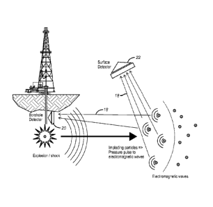
[0007] FIG. 1 shows the signal generating particles being delivered to
create the fracture;
[0008] FIG. 2 is the view of FIG. 1 showing the initiation of the shock
wave;
[0009] FIG. 3 shows the electromagnetic signal being generated; and
[0010] FIG. 4a shows the sensing of the signal(s) at the borehole and
surface locations;
[0010a] FIG. 4b is alternate embodiment of Fig. 4a.
DETAILED DESCRIPTION
[0011] At the beginning of the fracturing process (or, perhaps, even at
one
or more later times), a slug of microscopic triggerable sources 10 is mixed
with the proppants 12 in the fracturing fluid. This initial fluid slug should
be
the leading fluid that remains in contact with the outer edges of the
fracture.
Although hydraulic fracturing pressures can reach as high as 10,000 to 15,000
psi, there are 3M glass Microbubbles that can withstand up to 18 000 psi.
Using appropriately rated glass spheres (wall thickness and diameter in
microns), keeps them intact during the fracturing process. Afterwards, a
sudden pressure impulse 14 (such as a ram hitting a pressure piston or an
explosive charge) could be used to create a pressure spike 16 that breaks a
significant number of the glass spheres in their concentrated region near the
fracture's edges. The implosions of the glass spheres mechanically impacts the
smaller piezoelectric material 10 within the spheres to initiate an
electromagnetic signal 18 that is detected from multiple locations 20 in the
borehole and 22 at the surface and triangulated backward to their downhole
locations.
[0012] Alternatively, time, temperature, pH, (and, perhaps, pressure for
permeable coatings) act as triggers of these sources after the fracture has
been
3
CA 02907539 2015-09-16
WO 2014/149556
PCT/US2014/019553
completed. For example, a thin protective coating that degrades with time,
temperature, or pH is placed over a microscopic core of something that
chemically reacts very strongly with the fracturing fluid. When using pH as a
trigger, enteric coatings are resistant to acids (low pH) but readily dissolve
in
bases (high pH) and reverse-enteric coatings readily dissolve in acids but not
in bases. For example, the Group One metals (Lithium, Sodium, Potassium,
Rubidium, and Cesium) all react with water and the reaction intensity
increases with molecular weight so the strongest reaction is for Cesium, which
explodes upon contact with water and would apply a pressure pulse to the
piezoelectric material. Francium can be used but is less advantageous because
it is radioactive and it is only available in trace amounts.
[0013] A Group Two metal (Strontium) also reacts strongly with water as
do various other chemical compounds (Sodium Carbide, Calcium Carbide,
Aluminum Chloride, Lithium Hydride, Sodium Peroxide, etc.). Calcium
Carbide and Sodium Carbide may be less expensive and more readily
available materials as they are sometimes used in emergency flares or by
blacksmiths to generate acetylene on demand for welding torches. The choice
of degradable coating material and its thickness for the given environment of
temperature, pressure, and fracturing fluid, would determine the approximate
times at which these degradable protective coatings would be breached and
microscopic explosions of these triggerable sources would take place.
[0014] Microscopic triggerable electromagnetic (piezoelectric) sources
are
mixed with ordinary proppants in a fracture fluid during hydraulic fracturing
to allow these triggerable sources to be fired when it is believed that the
fractures have stopped propagating and, thereby, to determine the extent of
the
fracture. The trigger can be a pressure pulse that exceeds the hydrostatic
pressure rating of hollow glass microspheres (5 to 100 microns in diameter
with wall thicknesses about 2 percent of their diameters) and causes them to
implode and mechanically excite the smaller piezoelectric material within
them and create a spark of many electromagnetic frequencies. Conceptually, it
is similar to the sparking piezoelectric igniters used on natural gas
appliances.
When struck, they produce a spark, which includes a broad range of
electromagnetic frequencies, which, like lightning, can often be heard as
static
4
CA 02907539 2017-02-06
on a transistor radio regardless of the radio station to which it is tuned.
Alternatively, it could simply the passage of time at temperature which slowly
erodes an degradable protective coating over a highly-chemically-reactive core
(e.g., Cesium metal, sodium carbide, etc.) that reacts with the fracturing
fluid
(e.g., water) causing a "pop" upon contact that applies a pressure pulse to a
piezoelectric material and generates a corresponding electromagnetic signal
from the resulting spark, which includes a broad range of different
electromagnetic frequencies. The downhole locations of these triggered micro-
electromagnetic sources when they are fired would be determined by in-well
or surface electromagnetic detectors at multiple locations and by
triangulation.
100151 In a variation of
the method the material that receives the pressure
pulse can be a ferromagnetic or ferromagnetic material 10' whereby the
ferromagnetic or ferromagnetic material under the action of the shock pulse
transforms to a paramagnetic material subsequently generating a current and
voltage response as described by J. Johnson, "Theoretical and Experimental
Analysis of the Ferromagnetic Explosively Shocked Current Pulse Generator,"
J. Appl. Phys, 30 [4], 1959, pp241S-243S. It may further be appreciated that
the size, shape, and construct of the magnetic material or particle will
influence the subsequent I-V response to the shock pulse and therefore
correspondingly the measureable signal by which an embodiment of this
invention is enabled. Suitable particle morphologies can include simple
granular media with monomodal or multimodal distributions or also include
layered constructions of one or more materials, elongated particles, hollow
spheres or rods, platelets, fibers, and agglomerates thereof. Size range of
particles may extend from the nano-scale where the largest physical average
dimension measured linearly does is between 1 and 100 nanometers.
Additional sizes from 100 nm to 500 nm, 500 nm to 1 micron, 1 micron to 10
microns, and particles or clusters in excess of 10 microns to 1000 microns, or
particles and cluster between 1 mm and 10 mm are anticipated. Examples of
suitable ferromagnetic or ferromagnetic materials are elemental iron, nickel,
cobalt, dysprosium, gadolinium, and alloys of said materials. Also suitable
materials include chromium (IV) oxide, gallium manganese arsenide,
CA 02907539 2015-09-16
WO 2014/149556
PCT/US2014/019553
magnetite, samarium-cobalt, neodymium-cobalt, and similar alloys, yttrium
iron garnets, spinels of the form AB204, where A and B represent various
metal cations, usually including iron Fe, MnBi, Eu0, CrBr3, EuS, MOFe203,
and other oxides of iron, cobalt, and nickel. These magnetic materials can be
used singly, combined with one or more constituents, and also mixed with a
piezoelectric material 10 that in response to the pressure pulse also emits
electromagnetic energy that can be measured by sensors in the wellbore or/and
at the surface. It can be appreciated that the different materials have
different
magnetisms and therefore different responses to the shock pressure and
therefore the mixture of the materials and the injection sequence into the
wellbore would be chosen to maximize the embodiments of the invention. In
the downhole application, the sensor placement enables a triangulation
technique for allowing the computation of the configuration of the fracture.
[0016] Those skilled in the art will appreciate that the pressure pulse
can
be created in a variety of ways that in turn will allow the generation of
signals
from the leading fronts of the fracture. Depending on the material used and
the
timing of when it is pumped into the fracture and its concentration and other
variables, the signals that are received at spaced sensors can allow data to
be
processed that indicates not only the leading fronts of the fractures created
but
also intermediate data as to the fracture propagation between the borehole and
the leading fronts. The injected material during fracturing can be supplied as
a
uniform material initially added to the proppant or a material that is
integrated
with the proppant. The pressure pulse can be generated explosively or by a
reaction that is suitably delayed to allow placement in the borehole adjacent
the fracture regime or in the fractures themselves. The electromagnetic
signals
are generated in the fractures and the pulse can also be initiated at this
location.
[0017] The above description is illustrative of the preferred embodiment
and many modifications may be made by those skilled in the art without
departing from the invention whose scope is to be determined from the literal
and equivalent scope of the claims below:
6