Note: Descriptions are shown in the official language in which they were submitted.
CA 02907546 2015-09-17
WO 2014/147537
PCT/1B2014/059833
A PRECISION SURICAL GUIDANCE TOOL SYSTEM AND DELIVERY METHOD
FOR IMPLEMENTING DENTAL IMPLANTS
FIELD OF THE INVENTION
The present invention relates generally to dental implants and more
particularly to an improved
means and method for the preparation and insertion of dental implants.
BACKGROUND OF THE INVENTION
[01] A dental implant is an artificial prosthesis normally comprised of a
single cylindrical
component to replace the missing root structure of a natural tooth that has
been lost. This
standard implant is typically inserted into the jawbone by threading or
screwing it into a prepared
hollowed out bony site in the jawbone called in the field an osteotomy. The
prepared osteotomy
typically has a diameter that corresponds to the body dimensions of the
implant without its
threads and the threads of the implant engage (self-tap) the vertical inner
walls of the osteotomy
as it is screwed into place. The implant typically remains buried in the bone
(endosseous) for a
period of time to allow for "osseo-integration" or the growth and adhesion of
natural bone
around all the external surfaces of the implant, securing and stabilizing it
in place so that it can
withstand load forces. This cylindrical implant typically contains down its
internal center a
machined threaded internal hollow sleeve or bore that allows the dental
practitioner upon later
surgical exposure of the head or top (coronal) section of the cylindrical
implant to screw into
place a machined screw-in abutment (either with an integral screw on its
inferior aspect or a
separate connector screw which threads through a center hollow sleeve or bore
of the abutment).
The abutment, which extends into the oral cavity, is then utilized by the
dentist to fabricate a
single fixed prosthesis (crown), a multiple fixed prosthesis (dental bridges-
multiple crowns
connected to each other) in the case of adjacent multiple implants, or can
take the form of a fixed
prosthesis (over-denture bar prosthesis) to anchor a removable prosthesis such
as a permanent
denture, using techniques that are widely known in the dental field.
1
CA 02907546 2015-09-17
WO 2014/147537
PCT/1B2014/059833
[02] The upper and lower jaws are made up of a narrow strip of softer, spongy,
alveolar bone
sandwiched between two thin outer hard cortical plates of bone. In the
posterior regions the
entire width (cheek to tongue or buccal-lingual) of the jawbones is typically
only 5 to 7
millimeters thick. The average interdental (anterior-posterior length between
the teeth) space
remaining when a molar tooth is lost (missing tooth space) is typically 10 to
12 millimeters long.
The vertical depth of alveolar bone present where the tooth was lost can be as
little as 5 to10
millimeters before one encounters either the maxillary sinus space (in the
upper jaw) and the
inferior alveolar nerve (in the lower jaw).
[03] To allow for a proper volume or thickness of jaw bone between the implant
and the
adjacent teeth so as to allow for a proper blood supply and health of the bone
between the
implant and the adjacent teeth, it has been accepted in the dental field to
maintain a minimum
distance of 1.5 to 2 millimeters between the implant and the adjacent teeth on
either side of the
implant and 1.5 to 3 millimeters between adjacent multiple implants.
[04] This means that the target bone site for the proper placement of a dental
implant is very
limited and requires the practitioner who wishes to place dental implants
safely to exercise
considerable care performing the implant procedure after first having acquired
a high degree of
skill level and clinical experience. This becomes even more difficult for the
practitioner when
attempting to place multiple dental implants in the same jawbone.
[05] Dental implants are typically placed using the following two surgical
techniques:
1.Delayed technique: the unsalvageable tooth is extracted and the entire root
socket(s) are
allowed to heal with bone filling the void(s) over several months. Once this
healing process has
been completed, the practitioner opens the gum and drills into the bone to
create the osteotomy
(bone preparation) to allow for the insertion of the dental implant.
2.Immediate Extraction-
Immediate Implant technique: At the same visit, the practitioner extracts the
unsalvageable tooth
and immediately inserts the dental implant into the fresh root socket voids or
using a drill
modifies this root socket or drills a new hole and places the implant into it.
In the case of a molar
tooth extraction the practitioner is left with multiple proximal root socket
voids in the jawbone
2
CA 02907546 2015-09-17
WO 2014/147537
PCT/1B2014/059833
(where the multiple natural roots used to be) and an oval or rhomboid distal
void (where the root
trunk used to be).
[06] Both surgical techniques require the sequential use of a series of
increasing diameter and
or length bone drills to properly prepare the osteotomy and so allow for the
insertion of the
dental implant. This is required in order to safely remove bone tissue in a
gradient manner so as
not to overheat the surrounding bone as would invariably occur if the largest
diameter and length
bone drill was used initially instead of the above described drilling
protocol.
[07] It is well established medical fact that overheating bone tissue is
highly destructive to
surrounding bone tissue and leads invariably to necrosis of bone tissue, a
highly undesirable
outcome.
[08] The vast majority of dental implants are surgically inserted by the
dental practitioner into
the jawbones of the patient using the above two described surgical techniques
in a free-hand
manner (i.e. without the aid of any guidance system). As described above, this
means that the
dental practitioner in order to safely place dental implants relies solely on
his/her skill level
acquired through his experience, his latent natural talent, and his diligent
exercise of care
throughout the procedure. This required exercise of care and surgical skill
level defined above
applies both to both phases of the implantation procedure; namely: the bone
preparation
(osteotomy) and the subsequent insertion (implantation) of the dental implant
into said bone
preparation.
[09] It will be appreciated that if the practitioner errs to even a
relatively slight degree of 1-2
mm in any straight or angled direction (depth or position) while preparing the
osteotomy and
while inserting the implant into said bone preparation, s/he risks damaging
sensitive anatomical
structures as well as ending up with an implant placed in a non-optimal
position in relation to the
adjacent and opposing teeth and the final dental prosthesis placed onto the
implant which will be
used for functional biting and chewing and which relies on the implant for
structural load
support. The dental prosthesis will be secured to the implant once the implant
has osseo-
integrated (bone having grown in intimate contact around the exterior surface
of the implant so
3
CA 02907546 2015-09-17
WO 2014/147537
PCT/1B2014/059833
that it is now stable). As mentioned above, it will be further appreciated
that the required
accuracy and precision described above is compounded when multiple implants
are placed in the
same patient.
[010] In order to reduce the above skill requirements of the dental
practitioner, surgical guided
stents have in recent years begun to be used in the field in a limited
fashion. Such stents are
custom-made for each patient (discarded after a single use) and are fabricated
using elaborate
imaging equipment that has been wedded to sophisticated three dimensional
software computer
programs and which requires additional specialized dental laboratory
fabrication to produce said
stent.
[011] This process is both time-consuming and expensive for the dental
practitioner in terms of
delay of delivery of treatment to the patient, fees to the laboratory, and the
costs of the imaging
and software licenses. As the stent is custom made for each patient these
costs must be repeated
for each patient.
[012] The stent is usually made of acrylic materials and is custom shaped to
closely conform to
the alveolar ridges of the particular patient for whom they are to be placed
in, in order to assure
an intimate and accurate fit of the stent to the patient's mouth. Single or
multiple hollow metal
drill guide tubes are incorporated into the body of the stent at the
location(s) of the intended
implant target bone site(s).
[013] It will be appreciated that these drill guide tubes only provide a
location and angle for the
practitioner. In order to limit or control the vertical drilling depth, they
must be used in
conjunction with multiple hand-held instruments that have hollow rings of
varying diameters at
their working ends and whose rings have circumferential limiting flanges that
act as a stop limit
in regards to the vertical depth of the bone drill when said bone drill is
inserted into it.
[014] The varying diameters of the hollow rings of the hand-held instruments,
described above,
correspond to varying diameters (of the previously described) sequentially
used bone drills that
are used to prepare the osteotomy at the target bone site.
4
CA 02907546 2015-09-17
WO 2014/147537
PCT/1B2014/059833
[015] In order to secure a surgical stent to the patient's jawbone, multiple
pre-drilled holes are
incorporated into the stent on the buccal (cheek-side) side wall of the
alveolar ridge in a plane
that is perpendicular to the crest of the alveolar ridge. Multiple holes are
then drilled into the side
wall of the buccal surfaces of the jawbone of the patient by the practitioner
through said pre-
drilled stent holes and metal securing pins are screwed or tapped into these
holes to secure the
stent to the jawbone. It can be appreciated that this required method for
surgically securing the
stent is quite invasive to the patient and results in significant post-
operative pain and healing.
[016] The above stents are normally placed onto the jawbone after surgical
incisions are made
to the gum tissue and reflection of the gum tissue has been performed, though
some now
advocate their use without prior reflecting of the gum tissue.
[017] There is varying thickness of the gum tissue overlying the alveolar
ridges in different
patients so that reflecting the gum tissue prior to placing the stent onto the
alveolar ridge is
desirable as this allows for more accurate positioning of the stent directly
onto the coronal bone
surface of the alveolar ridge.
[018] The circumferential outer lip of the embedded ring tubes of the stents
can also be used as
a limiting flange to control the vertical depth to which the implant is
screwed/ threaded into the
osteotomy.
[019] It will be obvious that a guidance system that does not require a custom-
made surgical
stent for each patient yet allows for similar or improved guided drilling and
insertion of dental
implants would be most advantageous.
SUMMARY OF THE INVENTION
[020] In accordance with some embodiments, a one time or reusable universal
implanting
apparatus is provided which comprises a surgical clamp that contains an outer
frame, with
individually adjustable positioning elements, that clamps and secures itself
directly onto the bone
or onto the gums and bone and a separate and affix-able inner frame to said
outer frame whose
position and orientation is separately adjustable from the outer frame and
which allows for the
CA 02907546 2015-09-17
WO 2014/147537
PCT/1B2014/059833
securing of separate bone drilling and implant insertion guidance components
to the inner frame
element of the surgical clamp apparatus.
[021] According to some embodiments, an apparatus is provided that comprises:
a platform
suitable for being positioned over a bone and maintained in position for a
procedure including
preparing a bone for an implant and/or implanting an implant into a bone; one
or more frames
connected to the platform, wherein the one or more frames includes clamp arms
that extend to
opposing sides of the bone; one or more fixation cleats on each arm, wherein
each fixation cleat
has a tip suitable for penetrating into a bone and/or gum tissue on the
opposing sides of the bone
so that the frame is secured to the bone during the procedure; one or more
means for adjusting
the position of the each fixation cleats for securing the clamp arms to the
bone prior to and
during the procedure and for removing the clamp arms from the bone after the
procedure;
wherein the apparatus includes one or more features for positioning the
platform, for changing a
position of the platform, for changing an angle of a component of the platform
or any
combination thereof, following the securing of the clamp arms to the bone and
prior to the
procedure.
[022] In further embodiments, the bone is a jaw bone, and the procedure
includes preparing a
dental osteotomy and/or implanting a dental implant into a jaw bone.
[023] In further embodiments, at least a portion of the platform includes one
or more features
for changing an angle of the platform relative to the bone, so that the
apparatus can be used for
preparing one or more dental osteotomies optionally having bores with
different angles.
[024] In further embodiments, at least a portion of the platform includes one
or more features
for changing the direction of an angle of the platform relative to the bone,
so that the apparatus
can be used for preparing one or more dental osteotomies having bores with
different angles and
different directions of each angles.
[025] In further embodiments, at least a portion of the platform includes one
or more features
for changing the effective drilling height of the platform relative to the
bone, so that the
apparatus can be used for preparing two osteotomies having bores of different
depths.
6
CA 02907546 2015-09-17
WO 2014/147537
PCT/1B2014/059833
[026] In further embodiments, the arms of the frame have an upper region that
extend above the
crestal height and the occlusal plane of the teeth, wherein the upper region
of the arms have a
plurality of bore holes and are connected by one or more arm connection screws
extending
through a bore hole of each arm and by one or more arm guide pins extending
through a bore
hole of each arm, wherein the bore holes are aligned so that the arms are
maintained in a
generally parallel relationship.
[027] In further embodiments, the platform is connected to an inner frame, the
inner frame has
an upper portion, wherein the upper portion of the inner frame has bore holes
for receiving the
arm guide pins and the arm connection screw, wherein the bore holes of the
upper portion of the
inner frame have one or more features for securing the inner frame in a fixed
position relative to
the arm connection screws and the arm guide pins.
[028] In further embodiments, the arm connection screw is a left / right screw
so that both of
the arms of the outer frame can be simultaneously and/or equally moved towards
or away from
the platform.
[029] In further embodiments, the platform includes a lower guidance platform
and an upper
guidance platform.
[030] In further embodiments, the platform includes a swivel nut positioned
between the lower
guidance platform and the upper guidance platform.
[031] In further embodiments, the swivel nut has a bore hole extending that
length of the swivel
nut that is internally threaded, the platform includes an internally threaded
guide ring locking nut
and a drill guide ring, wherein the drill guide ring is generally cylindrical
with a bore through the
length for guiding a drill bit and the drill guide ring has an externally
threaded outer surface for
connecting the locking nut and the swivel nut.
[032] In further embodiments, the apparatus includes a screw that extends from
one of the arms
of the outer frame to the inner frame for adjusting the relative position of
the outer frame with
respect to the inner frame in the buccal to lingual direction.
7
CA 02907546 2015-09-17
WO 2014/147537
PCT/1B2014/059833
[033] In further embodiments, the apparatus includes a screw for locking the
position of the
inner frame relative to the position of the two arms of the outer frame
[034] In further embodiments, the apparatus includes one or more screws for
positioning and
locking the platform in the anterior to posterior axis relative to the inner
frame, relative to the
outer frame, or both.
[035] In further embodiments, the apparatus is sufficiently adjustable so that
it can be used for
implanting implants in a plurality of patients.
[036] In further embodiments, the apparatus is formed of materials capable of
being sterilized
after use in preparing an osteotomy so that the apparatus can be employed in
an osteotomy for a
different patient.
[037] In further embodiments, each arm of the outer frame has internally
threaded bore holes
for each of the cleats so that the each of the cleats can be screwed
individually against the gum,
and the arm connection screw has a knob for screwing the arms together so that
the cleats can
evenly penetrate the gum tissue and/or the bone independent of the curvature
of the gum tissue
and/or bone.
[038] In further embodiments, the apparatus is capable of preparing a vertical
osteotomy and is
also capable of preparing an osteotomy at an angle of about 10 or more from
the vertical axis.
[039] In further embodiments, the apparatus is capable of preparing an
osteotomy at an angle of
about 10 or more from the vertical axis and in a full 360 directional arc of
the horizontal axis.
[040] In further embodiments, the upper and lower guide platforms incorporate
internal
irrigation channels for directing irrigation fluid into the implanting bone
site.
[041] According to some embodiments, a process is provided that comprises the
steps of:
clamping a dental implantation apparatus to a jawbone, wherein the dental
implantation
apparatus includes a platform for guiding one or more tools for preparing an
osteotomy and/or
for implanting a dental implant into a jawbone; adjusting the position of the
platform relative to
the jawbone after the apparatus has been attached to the jawbone; and
maintaining the position of
8
CA 02907546 2015-09-17
WO 2014/147537
PCT/1B2014/059833
the platform while performing one or more steps of preparing an osteotomy
and/or implanting a
dental implant.
[042] According to some embodiments, the step of adjusting includes a step of
adjusting one or
any combinations of the following: a) adjusting the buccal to lingual position
of the platform; b)
adjusting the tilt angle of at least a portion of the platform relative to the
vertical axis; c)
adjusting the anterior to posterior position of the platform; or d) adjusting
the direction of the
projection of the tilt angle of the at least a portion of the platform onto
the plane perpendicular to
the vertical axis in a full 3600 range of motion of the horizontal axis.
[043] According to some embodiments, the dental implant apparatus includes an
outer frame
having two arms each having a lower portion that extends along opposing sides
of a jawbone,
and the apparatus includes a plurality of cleats protruding from each arm of
the frame, and the
step of clamping the apparatus includes inserting and engaging the each one of
the cleats
individually into gum tissue and/or into the bone.
[044] According to some embodiments, the process includes a step of measuring
a distance
between a portion of the platform and the crestal region of the jawbone for
calibrating the depth
for a step of preparing an osteotomy, wherein the step of measuring occurs
after a step of
adjusting the position of the platform.
[045] According to some embodiments, the process includes a step of measuring
the depth of
an osteotomy (e.g., relative to a portion of the platform) for calibrating an
insertion depth for
inserting an implant, wherein the step of measuring a depth occurs after a
step of adjusting the
position of the platform.
[046] According to some embodiments, the process is a process of implanting an
implant
immediately following the extraction of a tooth, wherein the process includes
one or any
combination of the following steps: a) inserting an adjustable extraction
socket gauge into a fresh
extraction socket and measuring the depth of the socket; b) Calibrating a
drill bit and/or an
implant driver based on a measured depth of a socket (e.g., using a
Calibration device); c)
adjusting a drill guide ring assembly to a desired position including desired
angle, to a desired
9
CA 02907546 2015-09-17
WO 2014/147537
PCT/1B2014/059833
direction, a desired depth, or any combination thereof, and locking this
position; d) inserting a
Calibrated drill bit and/or bushings into a drill guide ring to prepare an
osteotomy having an
including a desired angle, to a desired direction, a desired depth or any
combination thereof; or
e) inserting a Calibrated implant driver into a guide ring (e.g., a drill
guide ring) and installing an
implant at a desired angle, a desired direction, a desired depth, or any
combination thereof.
[047] According to some embodiments, the process comprises one or any
combination of the
following steps: a) extracting a tooth to form a socket; b) waiting for some
or all of the socket to
fill with bone; c) Calibrating a drill bit, an implant driver, an adjustable
gum thickness gauge, or
any combination therefor with a desired drill depth; d) securing a dental
implant apparatus to a
jaw bone at or near a dental implant site; e) adjusting a drill guide ring
assembly to a desired
position including a desired angle and/or a desired direction and locking this
desired position; f)
inserting the Calibrated gum thickness gauge into a drill guide ring, screwing
down the gum
thickness gauge until its tip penetrates the gum and rests on the bone of the
target implant site,
and remove the gum thickness gauge from drill guide ring, so that the guide
ring is calibrated to
drill to a desired drill depth; g) insert one or more drill bits and/or
bushings with a desired drill
depth into the drill guide ring for completing an osteotomy, wherein the drill
bit, the head of the
handpiece, and/or the bushing attached to the drill bit provide a limiting
flange when inserted
into the drill guide ring; or h) inserting a Calibrated implant driver
connected to an implant into
the drill guide ring, and screw down the implant with an implant driver into
the osteotomy.
[048] According to some embodiments, the process includes unclamping or
otherwise
removing the apparatus from the jawbone.
[049] According to some embodiments, the process includes a step of
sterilizing some or all of
the apparatus and a step of using the sterilized components for implanting an
implant in a
different patient.
[050] According to some embodiments, the process includes a step of preparing
a second
osteotomy at a different angle, a different direction, a different depth or
any combination thereof
CA 02907546 2015-09-17
WO 2014/147537
PCT/1B2014/059833
from the first osteotomy in either the same patient or in a different patient,
using the same
apparatus (e.g., using the same platform).
[051] According to some embodiments, a calibration device is provided,
comprising: a top
portion having one or more bore holes for receiving one or more gauges; a
bottom portion that is
spaced apart from the top portion; wherein the spacing between the top and
bottom portion is
adjustable; wherein the spacing between the top portion and the bottom portion
can be set to a set
position using a guide pin having a limiting flange ring for contacting the
bottom portion,
wherein the spacing is capable of being set by placing a gauge through one of
the bore holes of
the top portion so that the gauge just touches the top surface of the bottom
portion, wherein the
bottom portion has a bore hole for receiving a drill bit and/or an extraction
socket gauge so that
the drill bit or extraction socket gauge extends to the upper portion; and
wherein the upper
portion has calibration markings for calibrating the drill bit or the
extraction socket gauge; so
that the calibration apparatus can be used for drilling an osteotomy having a
predetermined
depth, and or for inserting an implant into an osteotomy to a predetermined
depth.
[052] According to some embodiments, the device includes a bore for receiving
an adjustable
bit from an extraction socket gauge, a bore for receiving an adjustable bit
from a gum thickness
gauge, and a bore for receiving an adjustable bit from an implant driver.
[053] According to some embodiments, an extraction socket gauge is provided,
with an
adjustable sliding center measuring bit that can be locked at various lengths
relative to the body
of the extraction socket gauge for the accurate measuring of an extraction
socket.
[054] According to some embodiments, an extraction socket gauge is provided
with an
adjustable sliding center measuring bit that can be locked at various lengths
relative to the body
of the extraction socket gauge for insertion into a drill guide ring, and
calibrating the drill depth
of an osteotomy.
[055] According to some embodiments, a gum thickness gauge is provided with an
adjustable
sliding center measuring bit that can be locked at various lengths relative to
the body of the gum
11
CA 02907546 2015-09-17
WO 2014/147537
PCT/1B2014/059833
thickness gauge for the accurate measuring of the thickness of the gum tissue
overlying the
alveolar crest of a jawbone.
[056] According to some embodiments, a gum thickness gauge is provided with an
adjustable
sliding center measuring bit that can be locked at various lengths relative to
the body of the gum
thickness gauge for insertion into a drill guide ring, and calibrating the
drill depth of an
osteotomy.
[057] According to some embodiments, an implant driver tool is provided with
an adjustable
sliding center measuring bit that can be locked at various lengths relative to
the body of the
implant driver tool for insertion into a drill guide ring, and calibrating the
depth the implant is
inserted into the osteotomy.
[058] According to some embodiments, a kit is provided that includes any
combination of two
or more of an implant driver tool, a gum thickness gauge, an extraction socket
gauge, or a
calibration device.
BRIEF DESCRIPTION OF THE DRAWINGS
[059] The principles and operation of the system, apparatus, and method
according to the
present invention may be better understood with reference to the drawings, and
the following
description, it being understood that these drawings are given for
illustrative purposes only and
are not meant to be limiting, wherein:
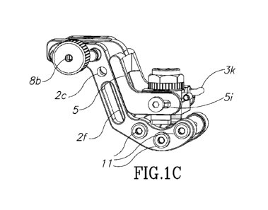
[060] Figs. 1A-1D show different perspectives of a surgical implant clamping
apparatus,
according to some embodiments;
[061] Figs. 2A-2E are graphical illustrations of some components of a surgical
implant
clamping apparatus, according to some embodiments;
[062] Figs. 3A-3I show different perspectives of graphical illustrations of a
guidance platform
of a surgical implant clamping apparatus;
12
CA 02907546 2015-09-17
WO 2014/147537
PCT/1B2014/059833
[063] Figs. 4A-4H are graphical illustrations of various elements related to
the guidance
position locking mechanism, according to some embodiments;
[064] Figs. 5A-5C are graphical illustrations of the guidance position locking
mechanism being
used with a surgical implant clamping apparatus, according to some
embodiments;
[065] Figs. 6A-6H are graphical illustrations of various components adapted
for use with a
surgical implant clamping apparatus, according to some embodiments;
[066] Figs. 7A-7G are graphical illustrations of various calibration related
components adapted
for use with a surgical implant clamping apparatus, according to some
embodiments;
[067] Figs. 8A-8E are graphical illustrations of calibration apparatus tools
adapted for use with
a surgical implant clamping apparatus, according to some embodiments;
[068] Figs. 9A-9C are graphical illustrations of some examples of the
calibration apparatus
being setup for treatment using a surgical implant clamping apparatus,
according to some
embodiments;
[069] Figs. 10A-10E are further graphical illustrations of calibration
components for use with a
surgical implant clamping apparatus, according to some embodiments;
[070] Figs. 11A-11F are graphical illustrations of a mandible being setup for
a delayed surgical
technique implantation treatment using a surgical implant clamping apparatus,
according to some
embodiments;
[071] Figs. 12A-12F are further graphical illustrations of a mandible being
setup for an
immediate surgical technique implantation treatment using a surgical implant
clamping
apparatus, according to some embodiments;
[072] Fig. 13 is a flow chart that describes a series of operations or
processes that may be
implemented to prepare a jaw bone for immediate placement of a dental implant,
according to
some embodiments; and
13
CA 02907546 2015-09-17
WO 2014/147537
PCT/1B2014/059833
[073] Fig. 14 is a flow chart that describes a series of operations or
processes that may be
implemented to prepare a jaw bone for delayed placement of a dental implant,
according to some
embodiments.
[074] It will be appreciated that for simplicity and clarity of illustration,
elements shown in the
drawings have not necessarily been drawn to scale. For example, the dimensions
of some of the
elements may be exaggerated relative to other elements for clarity. Further,
where considered
appropriate, reference numerals may be repeated among the drawings to indicate
corresponding
or analogous elements throughout the serial views.
DETAILED DESCRIPTION OF THE INVENTION
[075] The following description is presented to enable one of ordinary skill
in the art to make
and use the invention as provided in the context of a particular application
and its requirements.
Various modifications to the described embodiments will be apparent to those
with skill in the
art, and the general principles defined herein may be applied to other
embodiments. Therefore,
the present invention is not intended to be limited to the particular
embodiments shown and
described, but is to be accorded the widest scope consistent with the
principles and novel features
herein disclosed. In other instances, well-known methods, procedures, and
components have not
been described in detail so as not to obscure the present invention.
[076] Embodiments of the present invention enable dental implant treatments
using one time or
reusable surgical clamp apparatus and guidance system. Means and methods are
herein provided
for the preparation and insertion into bony tissue of standard implants, and
for positioning the
apparatus, for changing a position of the apparatus, for changing an angle of
a component of the
apparatus or any combination thereof, following the securing of the clamp
apparatus to the bone
and prior to the procedure, such that the bone/gum preparation and implant
insertion may be
conducted by a practitioner with precise guidance tools to enable enhanced
accuracy and safety.
According to some embodiments, the adjusting of the apparatus to a patient's
jawbone may
include adjusting the buccal to lingual position of the apparatus, adjusting
the tilt angle of at least
14
CA 02907546 2015-09-17
WO 2014/147537
PCT/1B2014/059833
a portion of the apparatus relative to the vertical axis, adjusting the
anterior to posterior position
of the apparatus; and/or adjusting the direction of the projection of the tilt
angle and the degree
of tilt angle from the vertical axis of the at least a portion of the platform
onto the plane
perpendicular to the vertical axis. In such dental implant treatments, whether
for immediate or
delayed surgical implantation treatments, the precision positioned and secured
guidance system
is able to provide the practitioner with the necessary depth and angle
measurement to enable
optimized and safe preparation and insertion of implants.
[077] The clamp apparatus may come in several standard sizes so as to allow
for matching a
particular size clamp apparatus to better fit inside a particular patient's
mouth and clamp properly
to different size jawbones.
[078] Figs. 1A-1D show different perspectives and components of an example of
a surgical
implant clamping apparatus 1, according to some embodiments. The surgical
clamp apparatus is
fabricated from sturdy materials that are bio-compatible with living tissue
and fluids can be
cleaned and repeatedly sterilized using known methods in the field. These may
include various
metal alloys such as different types of stainless steel or different types of
titanium or titanium
alloys. These may also include various surgical grade plastic materials or
other suitable
materials.
[079] Surgical clamp apparatus 1 may include a platform suitable for being
positioned over a
bone and maintained in position for a procedure including preparing a bone for
an implant
and/or implanting an implant into a bone , the platform being coupled to an
outer frame, which is
made up from two surgical clamp arms 2, connected by a right/left threaded
bolt 6, surrounded
by right/left bolt springs 10, and an inner frame 5, to enable the two clamp
arms to be closed and
opened simultaneously and optionally to the same degree along the buccal to
lingual axis.
[080] In some embodiments, the right and left clamp arms 2 are relatively "s"
shaped with a
relatively vertical central segment connected one either side to an upper and
lower relatively
horizontal segment and each arm matching the other in regards to dimensions.
Of course, other
forms may be used. Surgical clamp apparatus 1 may include an upper guide
platform 3 and a
CA 02907546 2015-09-17
WO 2014/147537
PCT/1B2014/059833
lower guide platform 4, for supporting surgical and implant guides. Also seen
in these figures are
right/left bolt adjusting knob 8 and guide plane adjusting knob 9.
[081] In some embodiments, inner frame 5 may consist of a single "s" shaped
component
which mirrors the "s" shape of the right and left clamp arms of the outer
frame. Of course, other
forms may be used. The inner frame's upper horizontal segment contains three
bore holes for the
insertion of the two- guide pins and the threaded center right/left bolt. The
inner frame is
assembled onto the - two guide pins and right /left threaded bolt between the
right and left clamp
arms of the outer frame. Inner frame 5 may have a horizontal and vertical
segment in the shape
of a "t" bar emerging from its upper horizontal segment which extends to the
inner borders of
both the right and left clamp arms. In some embodiments, the lower right and
left horizontal
segments of the inner frame serves as an outer frame for the insertion of the
guide platforms and
guidance position locking mechanism.In some embodiments, the center right/left
threaded bolt 6
may contain two spring coils around its respective right and left threaded
segments (between
either side of the inner frame and the right or left clamp arms) to create a
spring-loaded action to
the movement of the inner frame along the guide pins and threaded bolt.
[082] In some embodiments, the upper segment of each clamp arm contains three
bore holes
where the two outer ones are smooth and the center bore hole is internally
threaded. The two
outer bore holes are machined to allow for the insertion of a guide pin into
each bore hole.. The
center bore hole is machined to allow for the insertion of a right/left
threaded bolt with a knurled
knob on one of its ends. It will be appreciated that the center right/left
threaded bolt will be
inserted so that the right directional threads of the bolt insert into the
center bore hole of the right
clamp arm and the left directional threads of the bolt insert into the center
bore hole of the left
clamp arm.
[083] Such an assembly of the above parts allows for the two clamp arms to be
closed and
opened simultaneously (brought closer or further to each other) in a
symmetrically even manner
when the knurled knob (with its two locking nuts) is turned either clockwise
or counter-
clockwise. To further enhance this symmetrically even opening/closing
mechanism the two outer
16
CA 02907546 2015-09-17
WO 2014/147537
PCT/1B2014/059833
guide pins have limiting heads which face and engage a circumferential groove
on the knurled
knob of the center right/left threaded bolt.
[084] The relatively vertical segment of each arm may contains an internally
threaded bore hole
for the insertion of a set screw with a knob that allows for the adjustment
along the buccal to
lingual axis (cheek to tongue) of the inner frame when the inner frame is
attached to the other
frame. The lower horizontal segment of each clamp arm may contain multiple
internally threaded
bore holes which may be positioned in various positions relative to each other
in this clamp arm
segment.
[085] Each arm may include one or more fixation cleats with tips suitable for
penetrating into a
bone and/or gum tissue on the opposing sides of the bone so that the frame is
secured to the bone
during the procedure. The multiple internally threaded bore holes described
above accept the
insertion of variously designed individually adjustable fixation cleats 11
whose pointed tips (of
various shaped design) engage and penetrate a short distance either directly
into the side bony
walls (buccal and lingual plates) of the alveolar ridges or through both the
gums tissue overlying
the ridges and the bony ridges when the clamp arms are tightened towards each
other, by rotating
the knurled knob of the center right/left bolt, thereby stabilizing and
securing the clamp
apparatus at multiple locations on both the buccal and lingual aspects of the
patient's gums
and/or jawbone.
[086] Figs. 2A-2E are graphical illustrations of some components of the
surgical implant
clamping apparatus 1, according to some embodiments. As can be seen in Fig.
2A, surgical
clamp arms 2 may include a bore hole for guide pins 2a, a bore hole for
right/left bolt 2b, a bore
hole for guide plane elements adjusting knob 2c, bore holes for surgical
fixation cleats 2d, and a
clamp arm cleat holder segment 2e, for supporting the multiple fixation
cleats, designed to
engage the gum and or bony walls in a securing fashion.
[087] As can be seen in Fig. 2B, inner frame 5 may include an inner frame
upper bar 5a, an
inner frame pin bore 5b, an inner frame right/left bolt bore Sc, an inner
frame oval bore 5d, for
allowing lateral platform movement, an inner frame relatively vertical element
5e, an inner frame
17
CA 02907546 2015-09-17
WO 2014/147537
PCT/1B2014/059833
cross member 5f, an inner frame shelf 5g, an inner frame arm 5h with
calibrated markings on its
top surface 5i.
[088] As can be seen in Fig. 2C, the right/left bolt 6 is enclosed in an
adjusting knob 8 and a
right/left bolt set screws 8a and right/left know bolt driver tool slot 8b,
for turning the right/left
threaded bolt 6. Right/left bolt 6 is surrounded by right/left bolt springs 10
and guide pins 7,
which may include a guide pin head 7a, and a guide pin notch7b.
[089] As can be seen in Fig. 2D, inner frame adjusting knob 9 may include an
inner frame knob
head 9a, an inner frame knob threaded shaft 9b, and an inner frame knob
adjusting slot 9c.
[090] As can be seen in Fig. 2E, right/left threaded bolt 6 may include a left
section of
Right/Left bolt 6a, a right section of Right/Left bolt 6b, a center unthreaded
section of Right/Left
bolt 6c, an end section of Right/Left bolt 6d, and end section cut outs 6e for
facilitating the
securing of the adjusting knob 8 to this segment of the Right/Left bolt.
[091] Figs. 3A-3D show different perspectives of graphical illustrations of
the upper guidance
platform 3 of a surgical implant clamping apparatus, to enable precision bone
preparation and
implant delivery using standard implants. Surgical clamp apparatus 1 includes
upper guide
platform 3, which is supported by a lower guide platform 4 useful in implant
preparation. Upper
Guide Platform 3 may include a guide platform top surface 3a, an Upper Guide
platform locking
bore 3b, a Guide platform Locking screws 3c for Swivel nut 13, an Upper Guide
platform
center bore 3d, an Upper Guide platform irrigation tube bore 3e, an Upper
Guide platform center
bore with curved side walls 3f, an Upper Guide platform bottom irrigation
bores 3g, an Upper
Guide platform bottom surface 3h, an Upper Guide platform side wall 3i, an
Upper Guide
platform side wall cut out 3j, and an Upper Guide platform irrigation tube 3k,
for delivering
liquids to the treatment area.
[092] Figs. 3E-3H show different perspectives of graphical illustrations of
the lower guide
platform of a surgical implant clamping apparatus. Surgical clamp apparatus 1
includes a lower
guide platform 4, for further supporting precision implant preparation, in
association with upper
platform 3. Lower guide platform 3 may include a Lower Guide platform top
surface 4a, a Lower
18
CA 02907546 2015-09-17
WO 2014/147537
PCT/1B2014/059833
Guide platform bore 4b for Swivel nut 13 (not shown), a Lower Guide platform
irrigation
channels 4c, a Lower Guide platform center bore 4d, a Lower Guide platform
curved side walls
of center bore 4e, a Lower Guide platform shelf runner 4f, a Lower Guide
platform bottom
surface irrigation holes 4g, a Lower guide platform clamp arm side wall 4h,
and a Lower Guide
platform shelf locking nut bore 4i.
[093] As can be seen in Fig. 31, the upper and lower platforms may be coupled
such that a gap
12 remains between them. Gap 12 is designed in order to enable swivel nut 13
to be swiveled or
otherwise rotated or precisely positioned prior to locking engagement, as will
be described
below.
[094] Figs. 4A-4H are graphical illustrations of various components on the
guidance position
locking mechanism, to be used in association with the upper and lower guide
platforms,
according to some embodiments. As can be seen, the precision locking
mechanism, hereinafter
referred to as a drilling guide ring assembly 16, may include a swivel nut 13,
a Drilling Guide
Ring locking nut 14, and a Drilling Guide Ring 15.
[095] As can be seen in Figs. 4A-4B, Swivel nut 13 may include Swivel nut
curved outer side
walls 13a, Swivel nut threaded inner walls 13b, Swivel nut upper limiting
flange 13c, and
Swivel nut lower limiting flange 13d.
[096] As can be seen in Fig. 4C, Drilling Guide Ring locking nut 14 may
include Guide Ring
locking nut upper adjusting element 14a, Guide Ring locking nut bore threaded
inner side walls
14b, Guide Ring locking nut lower adjusting element 14b, and Guide Ring
locking nut lower
limiting flange 14d.
[097] As can be seen in Fig. 4D-4G, Drilling Guide Ring 15 may include
Drilling Guide Ring
inner adjusting element 15a, Drilling Guide Ring threaded outer side walls
15b, Drilling Guide
Ring bore inner walls 15c, and Drilling Guide Ring upper limiting flange 15d.
[098] Fig. 4H shows the drilling guide ring assembly 16 engaged with upper and
lower guide
platforms, to enable precision securing of the drill guide members so as to
enable secure and
precise bone preparation and implant installation by a practitioner. In one
example drilling guide
19
CA 02907546 2015-09-17
WO 2014/147537
PCT/1B2014/059833
ring assembly 16 engaged with upper and lower guide platforms may enable
precision securing
of the drill guide members so as to enable preparing a vertical osteotomy, and
is also capable of
preparing an osteotomy at an angle of about 10 or more from the vertical axis.
In a further
example, the swivel nut may be engaged with both the upper and lower guide
platforms, with the
gap allowing for swivel angles up to 15 degrees or more from the vertical "z"
axis in full 360
degree circle range from the "z" axis. When at its optimal angle for drilling,
the Swivel nut 13
may be locked in place, thereby establishing angular fixing, after tightening
the Guide platform
locking screws 3c between the upper 3 and lower 4 guide platforms. In some
embodiments ring
assembly 16 may be used to prepare one or more dental osteotomies optionally
having bores
with different angles.
[099] Figs. 5A-5C show different phases and views wherein the drilling guide
ring assembly 16
with its swivel nut 13, Drilling Guide Ring locking nut 14, and Drilling Guide
Ring 15, is
engaged with a surgical clamp apparatus 1, on the guide platform4. As can be
seen in Fig. 5A,
drilling guide ring assembly 16 is seated in lower platform 4 in platform
center bore 4D. In Fig.
5B the drilling guide ring assembly 16 is seated in both the upper 3 and lower
4 guide platforms
wherein is further illustrated a Drilling Guide Ring locking nut wrench 44.
Nut wrench 44 may
be used to tighten the drilling guide ring locking nut 14, when drilling guide
ring assembly 16 is
set up in the correct position, to secure the vertical position of the
drilling guide ring 15.. As can
be seen in Fig. 5C, a standard or specialized Implant drill hand-piece
attachment 17 may be used
to continue the procedure, by using surgical clamp apparatus 1 to support the
precision
preparation and execution of implant treatment when the handpiece 17 with its
attached drill bit
18 are fully inserted into the drilling guide ring assembly 16.
[0100] Figs. 6A-6H are graphical illustrations of various components adapted
for use with a
surgical implant clamping apparatus, according to some embodiments. As can be
seen in Fig. 6A,
a fixation cleat 11 may include a Fixation cleat limiting face 11a, a Fixation
cleat bone point 11b,
a Fixation cleat neck 11c, a Fixation cleat gum/bone point 11d, Fixation cleat
threaded shaft lie,
and a Fixation cleat adjusting slot llf. It is appreciated that these
configurations of the cleat may
be modified to allow for curved surfaces of bone and or gums.
CA 02907546 2015-09-17
WO 2014/147537
PCT/1B2014/059833
[0101] As can be seen in Fig. 6B, an Implant driver collet 22 of the Implant
Driver 19 (not
shown) is provided, which may include, for example an Implant driver collet
clamping prongs
22a, an Implant driver collet clamping prongs head 22b, an Implant driver
collet shaft 22c, an
Implant driver collet shaft limiting flange 22d, and an Implant driver collet
shaft bore 22e. As
can be seen in Fig. 6C, the Implant Driver 19 (not shown) may include an
Implant driver
adjustable driver shaft element 20 that may include, for example, an Implant
driver shaft 20a, an
Implant driver adjustable driver shaft top section 20b, and an Implant driver
flexing driver head
20c.
[0102] As can be seen in Fig. 6D, an Implant driver locking nut 21 is
provided, which may
include, for example, an Implant driver locking nut upper adjusting element
21a, an Implant
driver locking nut lower adjusting element 21b, an Implant driver locking nut
threaded bore 21c,
and an Implant driver locking nut lower limiting flange 21d.
[0103] As can be seen in Fig. 6F, an alternative perspective of the Implant
driver collet 22 is
provided, which may include, for example, Implant driver collet clamping
prongs 22a, an
Implant driver collet clamping prongs head 22b, an Implant driver collet shaft
22c, an Implant
driver collet shaft limiting flange 22d, and an Implant driver collet shaft
bore 22e. As can be
seen in Fig. 6E, Implant driver locking nut 21 is shown according to an
alternative perspective,
with Implant driver locking nut threaded bore 21c, and Implant driver locking
nut lower limiting
flange 21d.
[0104] As can be seen in Fig. 6G-6H, Adjustable implant driver 19 is shown,
with engaged
Implant driver locking nut 21 and Implant driver collet 22. Also shown is
Implant driver flexing
driver head 20c, for helping engage Dental Implant 23. As can be seen Fig. 61,
dental implant 23
may include, for example, an Implant threaded outer side wall 23a, an Implant
neck 23b, and an
Implant threaded internal bore 23c.
[0105] Figs. 7A-7G are graphical illustrations of various calibration related
components adapted
for use with a surgical implant clamping apparatus, to help determine precise
dimensions for
bone preparation and implant installation, according to some embodiments. As
can be seen in
21
CA 02907546 2015-09-17
WO 2014/147537
PCT/1B2014/059833
Fig. 7A, a Drill bit 18 is provided, which may include a Drill bit shank 18a,
a Drill bit shank
limiting flange 18b, a Drill bit cutting end 18c, and a Drill bit bushing 24.
[0106] As can be seen in Fig. 7B, a Gum thickness gauge inner shaft 26 is
provided, for
establishing gum thickness to enhance accuracy of bone drilling. Gum thickness
gauge inner
shaft 26 may include a Gum thickness gauge inner shaft main body 26a, and a
Gum thickness
gauge inner shaft probe element 26b.
[0107] As can be seen in Fig. 7C, a Gum thickness gauge locking nut 27 is
provided, which may
include a Gum thickness gauge locking nut upper adjusting element 27a, a Gum
thickness gauge
locking nut lower adjusting element 27b, and a Gum thickness gauge locking nut
threaded bore
27c.
[0108] As can be seen in Fig. 7D, a Gum thickness gauge collet 28 is provided,
to help set the
gauge at a selected setting. Collet 28 may include, for example, a Gum
thickness gauge collet
clamping prongs 28a, a Gum thickness gauge collet clamping prongs head 28h, a
Gum thickness
gauge collet shaft limiting flange 28c, a Gum thickness gauge collet shaft
28d, and a Gum
thickness gauge Drilling guide ring engaging element 28e. Fig. 7E shows an
alternative
perspective of gauge locking nut 27 engaged with gauge collet clamping prongs
28a. Fig 7E also
shows an alternative perspective of gauge locking nut 27 engaged with Gum
thickness gauge
collet shaft 28d and a Gum thickness gauge Drilling guide ring engaging
element 28e.
[0109] Fig. 7F shows a coupling of Gum thickness gauge inner shaft 26 and Gum
thickness
gauge collet 28, using Gum thickness gauge collet clamping prongs 28a. Also
seen is Gum
thickness gauge inner shaft probe element 26b penetrating through the length
of collet 28. Fig.
7G shows a coupling of perspective of the Adjustable gum thickness gauge 25,
which includes a
coupling of the Gum thickness gauge inner shaft 26, the Gum thickness gauge
locking nut 27,
and Gum thickness gauge collet 28.
[0110] Figs. 8A-8E are graphical illustrations of calibration apparatus tools
adapted for use with
a surgical implant clamping apparatus, according to some embodiments. As can
be seen in Figs.
8A-8B, a Pre-procedure Calibrating device guide pin shaft 30 is provided,
which includes
22
CA 02907546 2015-09-17
WO 2014/147537
PCT/1B2014/059833
Calibrating device guide pin shaft body 30a, a Calibrating device guide pin
knob engaging shaft
30b, a Calibrating device guide pin limiting flange ring 30c, and a
Calibrating device guide pin
screw element 30d. Further, a Calibrating device guide pin knob 31 is
provided, which may
include a Calibrating device guide pin knob outer side wall 31a, a Calibrating
device guide pin
knob locking screw 3 lb, a Calibrating device guide pin knob limiting flange
31c, and a
Calibrating device guide pin knob bore 31d. Fig. 8B shows a Calibrating device
adjustable guide
pin 29, which includes the coupling of the pin shaft 30 and guide pin knob 31.
[0111] Calibrating device 32 is used to help calibrate a variety of treatment
related instruments
for enhanced safety and accuracy in a procedure. Calibrating device 32 may
include, for
example, Calibrating device upper element 33, which may include a Calibrating
device upper
element cut out bore for adjustable implant driver 33a, a Calibrating device
upper element cut
out bore for adjustable gum thickness gauge 33b, a Calibrating device upper
element cut out bore
for lower element guide pin 33c, a Calibrating device upper element cut out
for drill bit or
extraction socket gauge 33d, and a Calibrating device upper element cut out
for drill bit or
extraction socket gauge calibrating markings 33e. Calibrating device 32 may
include, for
example, a Calibrating device lower element 34, which may include Calibrating
device lower
element top surface 34a, a Calibrating device lower element bore 34b, a
Calibrating device
lower element cut out 34c, and a Calibrating device lower element guide pin
34d. Fig. 8E further
shows guide pin knob 31 with a Calibrating device guide pin knob driver slot
31e. Further,
Calibrating device upper element 33 shows a Calibrating device upper element
cut out bore for
adjustable implant driver 33a, a Calibrating device upper element cut out bore
for adjustable gum
thickness gauge 33b, a Calibrating device upper element cut out bore for lower
element guide pin
33c, a Calibrating device upper element cut out for drill bit or extraction
socket gauge 33d, and a
Calibrating device upper element cut out for drill bit or extraction socket
gauge calibrating
markings 33e.
[0112] Figs. 9A-9C are graphical illustrations of some examples of the
calibration apparatus
being setup for treatment using a surgical implant clamping apparatus,
according to some
embodiments. Fig. 9A shows an Implant drill handpiece attachment 17 coupled to
Calibrating
23
CA 02907546 2015-09-17
WO 2014/147537
PCT/1B2014/059833
device 32, via Calibrating device lower element cut out 34c. As can be seen,
Drill bit length can
be selected in accordance with a practitioners professional opinion, for
example, a drill bit length
of choice for a treatment may be 13mm for preparing an osteotomy whose depth
is 13mm. The
drill bit is surrounded by a Drill bit bushing 24, to enable the Calibrating
device to set the the
drill bit at a selected length. Device 32 includes a Calibrating device upper
element 33, which
may include, for example, Calibrating device upper element cut out bore 33a
for adjustable
implant driver19, a Calibrating device upper element cut out bore 33b for
adjustable gum
thickness gauge25 , a Calibrating device upper element cut out bore for lower
element guide pin
33c, a Calibrating device upper element cut out 33d for drill bit 18 or
extraction socket gauge 35,
and a Calibrating device upper element calibrating markings 33e for
calibrating either the drill
bit 18 or extraction socket gauge 35.
[0113] Fig. 9B shows another perspective of Calibrating device 32, where an
Adjustable implant
driver 19 and an Adjustable gum thickness gauge 25 can be seen inserted and
being positioned
inside the Calibrating device upper element 33. Further, as can be seen, the
respective driver and
gauge penetrate though upper element 33 towards lower element 34 through the
respective cut
outs 33b and 33a of the Calibrating upper element 33,. A Calibrating device
guide pin knob 31
may be rotated to change the distance between the upper and lower elements, in
accordance with
the desired length for the drill bit 18. The inner shaft 20 of the Implant
driver 19 and the inner
shaft 26 of the gum thickness gauge can now be pushed down so as to be resting
on Calibrating
device lower element top surface 34a and in so doing calibrate both these
tolls to the desired
length previously set for the drill bit 18. Fig. 9C further shows the
Extraction socket adjustable
gauge 35 penetrating through the Calibrating device lower element cut out 34c
from below the
lower element so as to allow for the calibration of the Implant driver 19 to
the length previously
set for the Extraction socket adjustable gauge 35.
[0114] In further embodiments, Calibrating device 32 may include one or more
features for
changing the effective drilling height of the apparatus relative to the bone,
so that the apparatus
can be used for preparing two osteotomies having bores of different depths.
24
CA 02907546 2015-09-17
WO 2014/147537
PCT/1B2014/059833
[0115] Figs. 10A-10E are further graphical illustrations of calibration
components for use with a
surgical implant clamping apparatus, according to some embodiments. In Fig.
10A an Extraction
socket gauge shaft element 36 is provided for the Extraction socket gauge 35
(not shown), which
may include, for example, an Extraction socket gauge shaft body 36a, an
Extraction socket gauge
shaft upper calibrating section 36b, and an Extraction socket gauge shaft
lower calibrating
section 36c. In Fig. 10B an Extraction socket gauge collet 37 is shown, which
may include, for
example, Extraction socket gauge collet clamping prongs 37a, and Extraction
socket gauge collet
Drilling guide ring engaging element 37b. In Fig. 10C is shown an Extraction
socket adjustable
gauge locking nut 38, including an Extraction socket adjustable gauge locking
nut bore 38a. Fig.
10D shows the coupled engagement of the Extraction socket gauge shaft element
36 and the
Extraction socket gauge collet 37. Fig. 10E further shows different positions
of the Extraction
socket adjustable gauge 35, in accordance with different length settings.
[0116] In accordance with some embodiments, apparatus and methods are herein
provided to
enable Calibration of implant instruments outside the mouth, prior to the
invasive treatment. For
example, if a practitioner determines to use a drill bit set to lOmm implant,
Calibration apparatus
knob 31 may be turned to set the upper and lower apparatus elements to be set
at the appropriate
distance in accordance with the desired drill bit length. In turn, other
necessary tools, such as the
Adjustable implant driver 19 and Adjustable gum thickness gauge 25 may be
Calibrated in
accordance with the drill bit settings described above. All such tools may be
set at a desired
height and lock by rotation of a locking nut, locking collet and shaft. For
example, the Gum
thickness depth Gauge inner shaft 26 of the Gum thickness depth gauge 25 may
be placed at 10
mm in the Calibrating device 32 based on the length of the drill bit to be
used for the preparation
of the osteotomy. The Configured Gum thickness depth gauge 25may then be
removed from the
calibration tool, and dropped into the Drilling guide ring 15. In some
examples, a hex-type
element 28e of the Gum thickness depth gauge 25 with limiting flange may be
used to engage a
matching hex slot 15a of the Drill guide ring 15. The pre-set length of probe
26a of the Gum
thickness depth gauge 25 may be threaded down into the drill guide ring 15..
The practitioner
generally needs to screw the probe down until s/he feels the point at which
the driver end
CA 02907546 2015-09-17
WO 2014/147537
PCT/1B2014/059833
penetrates through the gum and engages the bone. The Drill guide ring is now
set to the depth
for bone drilling to the predetermined depth desired (based on the Chosen
drill bit length)
exclusive of the gum thickness depth overlying the bone. This method of
calibrating the Drill
Guide ring 15 allows for the practitioner to compensate for the variable gum
thickness in each
patient and to enable the drilling to a depth of 10 mm in jaw bone regardless
of the thickness of
the gum tissue overlying the bone at the target implant site.-
[0117] Figs. 11A-11F are graphical illustrations of a mandible being setup for
a delayed surgical
technique implanting treatment using a surgical implant clamping apparatus of
the present
invention, according to some embodiments. As can be seen in Fig. 11A, after
the Surgical clamp
apparatus 1 is placed and secured in position over a treatment area, the
Drilling Guide Ring 15 is
positioned over the Target implant site 39. In Fig. 11B, the Calibrated
Adjustable gum thickness
gauge 25 may be inserted into the Drill guide ring 15 and screwed down until
its probe
penetrates the gum tissue to the level of the bone. In Fig. 11C the Drill bit
18 is inserted into the
Dril guide ring 15 and rotated down (utilizing the handpiece 17-not shown)
until it rests on the
upper limiting flange 15a (not shown) of the Drill guide ring 15. In Fig. 11D,
an unobstructed
view (the clamp apparatus 1 has been removed from the drawing for illustration
purposes only)
of the Completed osteotomy 41 (prepared in Fig .11c) is revealed, in which the
Completed
osteotomy bony floor 41a and the Completed osteotomy bony side wall 41b can be
seen. In Fig.
11E the Calibrated Adjustable implant driver 19 (set to the pre-determined
length) is inserted
(with attached implant-not shown) into the Drill guide ring 15 and screwed
down until it rests on
the upper limiting flange 15d of the Drill guide ring 15 and may be used to
precisely drive the
implant into the completed osteotomy 41 via the Drill guide ring (which
remains at the height
previously set by the Gum thickness gauge 25) to the correct pre-determined
depth. In Fig. 11F
the Dental Implant 23 can be seen implanted in the target implant site 39 to
the desired pre-
determined depth.
[0118] Figs. 12A-12F are further graphical illustrations of a mandible being
setup for an
immediate surgical technique implantation treatment using a surgical implant
clamping apparatus
1 of the present invention, according to some embodiments. In Fig. 12A the
Extraction socket
26
CA 02907546 2015-09-17
WO 2014/147537
PCT/1B2014/059833
adjustable gauge 35 can be seen entered into the fresh Extraction socket 42
and its inner
adjustable shaft 36 pressed into the socket void to measure the depth of the
socket, and so to
verify the depth and angle etc. of the desired osteotomy preparation to be
drilled for the insertion
of the implant into the completed osteotomy (see Fig.12c). In Fig 12B the
clamp apparatus with
Drilling Guide Ring 15 can be seen positioned directly over the Extraction
socket 42. In Fig.
12C, the Extraction socket adjustable gauge 35 can be seen inserted into the
drilling guide ring
15 of the drilling guide ring assembly 16, to establish the optimal path for
drilling mentioned
above, which, once discovered via the gauge 35, can be locked or fixed in
place utilizing the
locking screws 3c and the Guide ring locking nut 14.
[0119] In Fig. 12d the drill bit 18 is inserted into the drill guide ring 15
and rotated (utilizing the
handpiece ¨not shown) until the limiting flange of the drill bit bushing 24
rests on the upper
limiting flange 15d (not shown) of the drill guide ring 15. In Fig. 12e the
Calibrated adjustable
Implant driver with implant connected to it (not shown) is inserted into the
drill guide ring 15
until it rests on the upper limiting flange 15d and so precisely drives the
implant to the correct
pre-determined depth. In Fig. 12F the Dental Implant 23 can be seen implanted
in the target
implant site 39 to the desired pre-determined depth.
[0120] According to some embodiments, a process is provided that comprises the
steps of:
clamping a dental implantation apparatus to a jawbone, wherein the dental
implantation
apparatus includes a platform for guiding one or more tools for preparing an
osteotomy and/or
for implanting a dental implant into a jawbone; adjusting the position of the
platform relative to
the jawbone after the apparatus has been attached to the jawbone; and
maintaining the position of
the platform while performing one or more steps of preparing an osteotomy
and/or implanting a
dental implant.
[0121] Fig. 13 schematically illustrates a series of operations or processes
that may be
implemented to prepare a jaw bone for immediate placement of a dental implant,
according to
some embodiments. As can be seen in Fig. 13, at step 13a, the tooth or teeth
needing to be
replaced by an implant is extracted. At step 13b, the bone is given time to
fill the socket of the
extracted tooth. At step 13c, prior to the implant preparation and
installation procedure, the
27
CA 02907546 2015-09-17
WO 2014/147537
PCT/1B2014/059833
selected drill bit, Implant Driver and Gum thickness Gauge may be Calibrated
to a desired drill
depth, with a Calibration Device. At step 13d a surgical guide clamp is seated
on the target site.
At step 13e a surgical guide clamp is secured on the target site. At step 13f
the Drill guide ring
assembly may be adjusted to a desired angle and direction, and is locked in
this position. At step
13g, the Calibrated Gum thickness Gauge is entered into Drill guide ring. At
step 13h the Gum
thickness gauge is screwed down until its tip penetrates gum and rests on the
bone of the target
implant site. At step 13i the Gum thickness Gauge is removed from the Drill
guide ring. At step
13j the drill guide ring is calibrated to the desired drill depth. At step 13
k the drill bits and
bushings with desired drill depth are inserted into the Drill guide ring. At
step 131 the Osteotomy
(bone preparation) is completed, using the selected drill bit, length, angle
etc. At block 13m the
Calibrated Implant Driver connected to the Implant is inserted into the Drill
Guide Ring. At
block 13n the implant is screwed down with the Implant Driver into the
Osteotomy. At step 13o
the clamp may be removed. Further, other steps or series of steps may be used.
[0122] Fig. 14 schematically illustrates a series of operations or processes
that may be
implemented to prepare a jaw bone for delayed placement of a dental implant,
according to some
embodiments. As can be seen in Fig. 14, at step 14a, the Extraction Socket
Gauge is inserted into
the Fresh extraction socket, to measure the socket depth. At step 14c, prior
to the implant
preparation and installation procedure, the selected drill bit, Implant Driver
and Gum thickness
Gauge may be Calibrated to a desired drill depth, with a Calibration Device,
in accordance with
the depth measured by the Extraction Socket Gauge. At step 14d a surgical
guide clamp is seated
on the target site. At step 14e a surgical guide clamp is secured on the
target site. At step 14f the
Extraction Socket Gauge is inserted into the Calibration device and set to
Calibrated drill bit
length. At step 14g insert the Calibrated Extraction Socket Gauge into the
Drill Guide Ring
assembly. At step 14h the Drill guide ring assembly may be adjusted to a
desired angle and
direction, and is locked in this position. At step 14i, the Drill guide ring
is now calibrated to
desired drill depth. At block 14j the drill bits and bushings with desired
drill depth are inserted
into the Drill guide ring. At step 14k the Osteotomy (bone preparation) is
completed, using the
selected drill bit, length, angle etc. At block 141 the Calibrated Implant
Driver is connected to the
28
CA 02907546 2015-09-17
WO 2014/147537
PCT/1B2014/059833
Implant and inserted into the Drill Guide Ring. At block 14m the implant is
screwed down with
with Implant Driver into the Osteotomy. At step 14n the clamp may be removed.
Further, other
steps or series of steps may be used.
[0123] According to some embodiments, a kit is provided that includes any
combination of two
or more of an implant driver tool, a gum thickness gauge, an extraction socket
gauge, or a
calibration device.
[0124] The foregoing description of the embodiments of the invention has been
presented for the
purposes of illustration and description. It is not intended to be exhaustive
or to limit the
invention to the precise form disclosed. It should be appreciated by persons
skilled in the art that
many modifications, variations, substitutions, changes, and equivalents are
possible in light of
the above teaching. It is, therefore, to be understood that the appended
claims are intended to
cover all such modifications and changes as fall within the true spirit of the
invention.
29