Note: Descriptions are shown in the official language in which they were submitted.
CA 02907555 2015-09-17
WO 2014/153358
PCT/US2014/031088
MODULE PLACEMENT DEVICE AND METHOD
FIELD OF THE INVENTION
[0001] The present invention relates generally to the field of precision
automated
manufacturing. More particularly, the present invention relates to a device
and method
for automatically placing a module on the underside of an object using optical
cues to
align the module to the object.
BACKGROUND AND SUMMARY
[0002] Modern automotive mirrors are being called upon to provide more
than
just a reflective surface for viewing next to or behind the vehicle. In many
cases it is
desirable to provide the driver with information using the mirror surface but
enable the
complete mirror surface to be reflective when the information is not being
provided. For
example, a rear view mirror might include icons indicative of direction,
vehicle functions
such as telephone use, and other information and a side view mirror may warn a
driver
that the turn signal is activated or the side view mirror may be connected to
a blind spot
detection system so that the driver can be warned about a vehicle in the blind
spot. In
order to achieve a usable mirror surface when the icons are not activated, a
number of
techniques have been developed. One common technique is to use fine ablations
of the
reflective surface so that light can pass therethrough but a substantial
portion of the
reflective surface remains intact. When the light behind the mirror for the
icon is
activated it passes through the ablation and can be seen and when the light is
not
activated the mirror effect remains substantially intact.
[0003] Certain automotive manufactures desire highly detailed icons to
appear in
the mirrors, with a high degree of light, and minimal affect on normal mirror
operation.
1
CA 02907555 2015-09-17
WO 2014/153358
PCT/US2014/031088
To achieve these requirements, mirror manufacturers have found it necessary to
precisely
align highly-engineered reflectors and light sources (these highly-engineered
reflectors
and light sources are referred to herein as "modules") behind finely ablated
mirrors.
Traditionally, these modules have been positioned against the mirror backs by
hand but in
the manufacturing process this can lead to an unacceptably high level of
rejected parts
due to failure to meet performance objectives. As such, there is a need for a
high-
precision device and method to mate a module to a mirror substrate.
[0004] The present invention relates to a device and method to precisely
mate a
highly-engineered light source and reflector module to the rear of a mirror
substrate. The
device and method include the ability to place the module and substrate into
fixtures,
reposition at least one of the module and the substrate, and then press the
two together so
that the module adheres to the rear of the substrate. The device and method
could have
other applications where similar performance characteristics are desirable.
[0005] It will be understood by those skilled in the art that one or more
aspects of
this invention can meet certain objectives, while one or more other aspects
can lead to
certain other objectives. Other objects, features, benefits and advantages of
the present
invention will be apparent in this summary and descriptions of the disclosed
embodiment,
and will be readily apparent to those skilled in the art. Such objects,
features, benefits
and advantages will be apparent from the above as taken in conjunction with
the
accompanying figures and all reasonable inferences to be drawn therefrom.
BRIEF DESCRIPTION OF THE DRAWINGS
[0006] FIG. 1 is a perspective view of one embodiment of a module
placement
device in accordance with the invention;
2
CA 02907555 2015-09-17
WO 2014/153358
PCT/US2014/031088
[0007] FIG. 2 is another perspective view of the module placement device
of FIG.
1 with the protective housing removed;
[0008] FIG. 3 is a detail view of the module placement device of FIG. 1
showing
the vertical movement of the substrate clamp arm;
[0009] FIG. 4 is a flow chart depicting an operation sequence of a device
and
method in accordance with one embodiment of the invention;
[0010] FIG. 5 is another detail view of the module placement device of
FIG.1
showing the initial horizontal movement of the module fixture;
[0011] FIG. 6 is another detail view of the module placement device of
FIG.1
showing the calibrating vertical movement of the module fixture;
[0012] FIG. 7 is another detail view of the module placement device of
FIG.1
showing the lowering of the module fixture before placement of the module;
[0013] FIG. 8 is another detail view of the module placement device of
FIG.1
showing the movement of the module fixture into placement position;
[0014] FIGS. 9-11 are side section views of the module placement device
of
FIG.1 taken generally along the line 8-8 in FIG. 7 showing placement of the
module onto
the substrate;
[0015] FIG. 12 is another detail view of the module placement device of
FIG.1
showing removal of the substrate with the module attached; and
[0016] FIG. 13 is another detail view of the module placement device of
FIG.1
showing the degrees of movement of the module fixture.
3
CA 02907555 2015-09-17
WO 2014/153358
PCT/US2014/031088
DETAILED DESCRIPTION
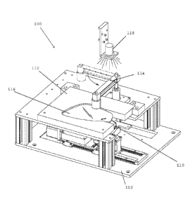
[0017] FIGS. 1-3 and 5-13 show one embodiment of a module placement
device
100 in accordance with the invention. The module placement device 100 stands
on a base
102 and has a protective housing 104. In the embodiment shown, the protective
housing
104 includes safety provisions to prevent unintended operation of the module
placement
device 100 while an operator's hand is near the device. Such safety provisions
may
include light curtains, emergency stop switches, two hand controls, mechanical
guards, or
any other suitable means without departing from the invention. Near the module
placement device 100 is an operator interface 106 that allows an operator to
configure
and monitor operation of the module placement device. In the embodiment shown,
the
operator interface 106 is a touch screen attached to the protective housing
104, but any
other user interface may be used without departing from the invention.
Alternatively, the
user interface may include but are not limited to a computer with keyboard and
mouse, or
may be replaced by a programmable logic controller or equivalent.
[0018] Turning now to FIG. 2, a detail view of the module placement
device 100
is shown. The module placement device includes a module fixture 110, and a
substrate
fixture 112. In the embodiment shown, the substrate fixture 112 is for the
placement of a
blind spot monitor alert light on a side view car mirror, but any suitable
substrate may be
used without departing from the invention. The module fixture 110 is attached
to a
plurality of actuators and motors that move the module fixture during the
module
placement process. The substrate fixture 112, on the other hand, remains
stationary
throughout the module placement process. Of course, the module fixture 110
could
remain stationary while the substrate fixture 112 moves without departing from
the
4
CA 02907555 2015-09-17
WO 2014/153358
PCT/US2014/031088
invention. As shown in greater detail in FIG. 3, a substrate clamp arm 114 is
located near
the substrate fixture 112 that secures a substrate 116 to the substrate
fixture during the
module placement process. A camera 118 is positioned above the module fixture
110.
[0019] The operator interface 106, module fixture 110, and camera 118 are
connected to a controller that controls the operation of the module placement
device 100.
In the embodiment shown, the controller includes a processor, memory, and
program that
moves the module fixture 110 based on images captured by the camera 118. A
program is
loaded into the controller based on the geometry of the substrate and the
module being
placed.
[0020] Turning now to FIGS. 4-11, one cycle of the operation of the
module
placement device 100 is shown. FIG. 4 is a flowchart showing a typical module
placement cycle. FIGS. 5-11 show the module placement device 100 in various
stages of
the module placement cycle. The module placement device 100 works by visually
identifying landmarks on the substrate 116 and a module 118 to automatically
and
precisely align the substrate and module together. In the embodiment shown,
the module
118 has an adhesive face that permanently bonds to the substrate 116 when the
module is
pressed onto it. Of course, the module 118 could be non-adhesive, with
adhesive on the
substrate 116 without departing from the invention. Just prior to the start of
an operation
cycle of the module placement device 100, an operator places a module 118 in
the
module fixture 110. Next, the operator starts the module placement device 100
by
pressing a button on the operator interface 106 or by any other suitable
means. FIG. 5
shows the movement of the module fixture 110 into a position beneath the
camera 118.
Next, as shown in FIG. 6, the module fixture 110 raises to the height of the
substrate 116.
CA 02907555 2015-09-17
WO 2014/153358
PCT/US2014/031088
The camera 118 is focused on both the substrate 116 and the module 118 and the
controller, based on the image captured by the camera when the module fixture
is raised
to the height of the substrate 116, calculates the position of the module
relative to the
substrate. In the embodiment shown, the controller recognizes landmarks on the
module
118 and the substrate 116 and uses software to calculate how to align them to
each other.
Multiple cameras could be used without departing from the invention.
[0021] Turning now to FIG. 7, the controller moves the module fixture 110
back
to a descended position so it can move beneath the substrate. At the same
time, the
controller moves the module fixture 110 based on the calculation described
above so that
the module 118 is properly aligned with the substrate 116. FIG. 8 shows the
movement of
the module fixture 110 into position beneath the substrate 116.
[0022] FIGS. 9-11 show how the module 118 is placed on the substrate 116.
In
FIG. 9, the module fixture 110 is positioned beneath the substrate and in
position to be
affixed to the substrate. FIG. 10 shows the module fixture 110 raised so that
the module
118 is pressed onto the substrate 116. FIG. 11 shows the module fixture 110
descending
back to its position in FIG. 9, with the module 118 affixed to the substrate
116. After the
module 118 is affixed to the substrate 116, the substrate clamp arm 114 raises
and swings
away, allowing the operator to remove the now completed part 120 (FIG. 12).
[0023] FIG. 13 shows the module fixture 110 in greater detail. In the
embodiment
shown, the module fixture is movable in four directions. The module fixture
110 is
movable in the X, Y, and Z axes, as well as a rotational axis around the Z
axis. Providing
four axes of available movement allows the module 118 to be precisely placed
on the
substrate 116. In the embodiment shown, three stepper motors 122 and a linear
actuator
6
CA 02907555 2015-09-17
WO 2014/153358
PCT/US2014/031088
control the movement of the module fixture 110. The stepper motors 122 control
X, Y,
and rotational position, and the linear actuator controls the position of the
module fixture
110 along the Z axis. Using stepper motors 122 allows precision control of the
position of
the module fixture 110, but any other suitable means may be used without
departing from
the invention.
[0024] Although the invention has been herein described in what is
perceived to
be the most practical and preferred embodiments, it is to be understood that
the invention
is not intended to be limited to the specific embodiments set forth above.
Rather, it is
recognized that modifications may be made by one of skill in the art of the
invention
without departing from the spirit or intent of the invention and, therefore,
the invention is
to be taken as including all reasonable equivalents to the subject matter of
the appended
claims and the description of the invention herein.
7