Note: Descriptions are shown in the official language in which they were submitted.
CA 02907556 2015-09-16
DESCRIPTION
TITLE OF THE INVENTION:
POROUS CARBON MATERIAL, PRECURSOR FOR POROUS CARBON
.. MATERIAL, PROCESS FOR PRODUCING PRECURSOR FOR POROUS CARBON
MATERIAL, AND PROCESS FOR PRODUCING POROUS CARBON MATERIAL
TECHNICAL FIELD
[0001]
The present invention relates to a porous carbon material which can be used
in various applications, a porous-carbon-material precursor, a process for
producing the
porous-carbon-material precursor, and a process for producing the porous
carbon
material.
BACKGROUND ART
[0002]
As porous carbon materials, activated carbons having both macropores
which are relatively large pores and micropores, such as particulate activated
carbons
and activated-carbon fibers; and fine carbons represented by carbon nanotubes
and
mcso-porous carbons produced from a meso-porous silica or zeolite template,
are
known.
[0003]
Of these, the activated carbons are in use as adsorbent materials and catalyst
supports mainly in the field of industrial materials so as to take advantage
of the large
specific surface area thereof. In particular, since pores are formed by
activating a bulk
material which has been carbonized beforehand, the activated carbons further
have an
1
CA 02907556 2015-09-16
advantage in that porous materials can be supplied at relatively low cost.
However, in
general activation processes, pores are formed unidirectionally from the
surface of the
carbon material toward the inner part thereof and, hence, it is difficult to
produce a
material having communicating pores which are pores that communicate with one
another. There has hence been a problem concerning application to composite
materials, for example, because it is difficult to highly fill another
material into the
pores.
[0004]
Patent Document 1 describes a technique for obtaining porous carbon fibers
by mixing a carbonizable material with an eliminable material. However, the
carbonizable material and the eliminable material are a combination which
forms a non-
compatible system. and the mere addition of a compatibilizing agent was unable
to form
continuous pores.
[0005]
Patent Document 2 describes a technique in which the porous carbon fibers
described in Patent Document 1 are further activated to form pores therein,
thereby
producing activated-carbon fibers. However, since the activation step is
intended to
form pores from the surface of the carbon material mainly by oxidation as
stated above,
this technique also failed to form continuous pores.
[0006]
Patent Documents 3 and 4 show examples in which a carbon material which
itself has a continuous porous structure introduced thereinto is produced by
mixing a
thermosetting resin with a thermoplastic resin, curing the thermosetting
resin,
subsequently removing the thermoplastic resin, and then performing
carbonization.
BACKGROUND ART DOCUMENT
2
CA 02907556 2015-09-16
PATENT DOCUMENT
[0007]
Patent Document 1: JP-A-2-160923
Patent Document 2: JP-A-2-160924
Patent Document 3: JP-A-2004-259593
Patent Document 4: JP-A-2006-240902
SUMMARY OF THE INVENTION
PROBLEMS THAT THE INVENTION IS TO SOLVE
[0008]
The present invention provides a porous carbon material which
simultaneously includes a portion having continuous pores and a portion having
no
continuous pores and which, due to this configuration, is excellent in
electrical
conductivity, thermal conductivity, pressure resistance, and strength for
withstanding
tension or compression.
MEANS FOR SOLVING THE PROBLEMS
[0009]
A first embodiment of the present invention is a porous carbon material
which includes a portion having a continuous porous structure and a portion
having
substantially no continuous porous structure, in which the portion having the
continuous
porous structure has a structural period of 0.002 to 1 gm.
[0010]
A second embodiment of the present invention is a porous-carbon-material
precursor which includes a portion having a continuous porous structure and a
portion
3
CA 02907556 2015-11-19
55224-13
having substantially no continuous porous structure, in which the portion
having the
continuous porous structurel has a structural period of 0_003 to 2 urn.
[0011]
A third embodiment of the present invention is a porous-carbon-material
precursor including a portion where a carbonizable resin and an eliminable
resin each
form a continuous phase and a portion that is substantially constituted only
of a
carbonizable resin, in which the portion where the carbonizable resin and the
eliminable
resin each form the continuous phase has a structural period of 0.003 to 2
urn.
[0012]
A fourth embodiment of the present invention is a process for producing a
porous-carbon-material precursor, the process including:
step 1: a step in which 10 to 90% by weight of a carbonizable resin and 90
to 10% by weight of an eliminable resin are brought into a compatibly mixed
state to
obtain a resin mixture; and
step 2: a step in which the resin mixture obtained in the step 1 is caused to
undergo phase separation and the separated phases are fixed.
[0013]
A fifth embodiment of the present invention is a process for producing a
porous carbon material, the process including:
step 1: a step in which 10 to 90% by weight of a carbonizable resin and 90
to 10% by weight of an eliminable resin are brought into a compatibly mixed
state to
obtain a resin mixture;
step 2: a step in which the resin mixture obtained in the step 1 is caused to
undergo phase separation and the separated phases are fixed to obtain a porous-
carbon-
material precursor; and
4
81791564
step 3: a step in which the porous-carbon-material precursor obtained in the
step 2
is carbonized by pyrolysis.
[0013a]
There is further provided a porous carbon material which comprises a portion
having a continuous porous structure and a portion having substantially no
continuous porous
structure, wherein when a cut surface of the portion having the continuous
porous structure is
examined with a scanning electron microscope, a structure in which branches
and pores are
respectively continued inward is observed, and wherein the portion having the
continuous
porous structure has a structural period of 0.002 to 1 gm.
[0013b]
There is further provided a porous-carbon-material precursor which comprises a
portion having a continuous porous structure and a portion having
substantially no continuous
porous structure, wherein when a cut surface of the portion having the
continuous porous
structure is examined with a scanning electron microscope, a structure in
which branches and
.. pores are respectively continued inward is observed, and wherein a central
part of the
continuous porous structure has a structural period of 0.003 to 2 gm.
[0013c]
There is further provided a porous-carbon-material precursor comprising a
portion
where a carbonizable resin which carbonizes upon pyrolysis and remains as a
carbon material
and an eliminable resin which is removable simultaneously with treatment for
imparting
infusibility, after treatment for imparting infusibility, or simultaneously
with the pyrolysis,
each form a continuous phase and a portion that is substantially constituted
only of a
carbonizable resin, wherein the portion where the carbonizable resin and the
eliminable resin
each form the continuous phase has a structural period of 0.003 to 2 gm.
[0013d]
There is further provided a process for producing a porous-carbon-material
precursor, the process comprising: step 1: a step in which 10 to 90% by weight
of a
carbonizable resin which carbonizes upon pyrolysis and remains as a carbon
material and 90
5
CA 2907556 2019-07-10
81791564
to 10% by weight of an eliminable resin which is removable simultaneously with
treatment
for imparting infusibility, after treatment for imparting infusibility, or
simultaneously with the
pyrolysis, are brought into a compatibly mixed state to obtain a resin
mixture, the
compatibility mixed state being a state that no structure in which the
carbonizable resin and
the eliminable resin are present as separate phases is observed with an
optical microscope; and
step 2: a step in which the resin mixture obtained in the step 1 is caused to
undergo phase
separation and the separated phases are fixed, and wherein the phase
separation accompanies
no chemical reaction.
[0013e]
There is further provided a process for producing a porous carbon material,
the
process comprising: step 1: a step in which 10 to 90% by weight of a
carbonizable resin which
carbonizes upon pyrolysis and remains as a carbon material and 90 to 10% by
weight of an
eliminable resin which is removable simultaneously with treatment for
imparting infusibility,
after treatment for imparting infusibility, or simultaneously with the
pyrolysis, are brought
into a compatibly mixed state to obtain a resin mixture, the compatibility
mixed state being a
state that no structure in which the carbonizable resin and the eliminable
resin are present as
separate phases is observed with an optical microscope; step 2: a step in
which the resin
mixture obtained in the step 1 is caused to undergo phase separation and the
separated phases
are fixed to obtain a porous-carbon-material precursor, wherein the phase
separation
accompanies no chemical reaction; and step 3: a step in which the porous-
carbon-material
precursor obtained in the step 2 is carbonized by pyrolysis.
ADVANTAGE OF THE INVENTION
[0014]
According to the invention, due to the portion having the continuous porous
structure, it is possible to impart a function by filling and/or passing a
fluid into or through the
pores which constitute the continuous porous structure. Furthermore, since
branches are
continued, the electrical conductivity and the thermal conductivity are
heightened to some
degree. In addition, an effect in which the branches support one another to
maintain the
5a
CA 2907556 2019-07-10
81791564
structure is produced, and due to this effect, the material has some degree of
resistance to
deformations such as ones caused by tension or compression. Since the material
of the
present invention not only has the portion having the continuous porous
structure but also
includes a portion having substantially no continuous porous structure, the
electrical
conductivity and thermal conductivity are further heightened and it is
possible to remarkably
enhance the resistance to deformations caused by tension, compression, etc.,
in particular,
resistance to compressive rupture. Especially in the case where the material
has a
configuration in which the portion having no continuous porous structure
covers the portion
having the continuous porous structure, it is possible to more efficiently and
easily impart a
function by filling and/or passing a fluid into or through the pores which
constitute the
continuous porous structure.
BRIEF DESCRIPTION OF THE DRAWINGS
[0015]
5b
CA 2907556 2019-07-10
CA 02907556 2015-09-16
,
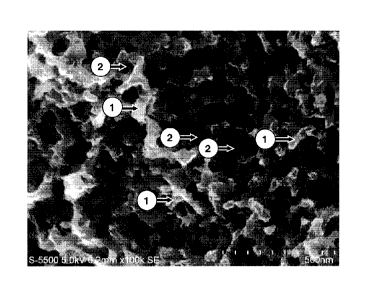
[Fig. 1] Fig. 1 is a scanning electron photomicrograph of the porous
carbon material of Example 1.
[Fig. 2] Fig. 2 is a transmission electron photomicrograph of the porous-
carbon-material precursor of Example 9, which has no pores.
[Fig. 31 Fig. 3 is a transmission electron photomicrograph of the porous-
carbon-material precursor of Example 10, which has pores.
MODE FOR CARRYING OUT THE INVENTION
[0016]
<Porous Carbon Material>
The porous carbon material (hereinafter sometimes referred to simply as
"material") of the invention includes a portion having a continuous porous
structure and
a portion having substantially no continuous porous structure.
[0017]
The term "continuous porous structure" in the porous carbon material of the
invention means that when a specimen of the porous carbon material which has
been
sufficiently cooled, for example, in liquid nitrogen is cut with tweezers or
the like and
the cut surface is examined with a scanning electron microscope (SEM) or the
like, then
a structure in which branches (carbon part) 1 and pores (voids) 2 are
respectively
continued inward is observed, specifically as shown in Fig. 1 that is a
scanning electron
photomicrograph of the porous carbon material of Example I.
[0018]
The portion having the continuous porous structure in the porous carbon
material of the invention can be made to exhibit the fractionating properties
such as
separation, adsorption, or elimination, by filling and/or passing a fluid into
or through
the pores which constitute the continuous porous structure, or can be made to
have
6
CA 02907556 2015-11-19
55224-13
functions required for battery materials by using an electrolytic solution.
Furthermore,
since the continued branches bring about increased electrical conductivity and
thermal
conductivity, not only the porous carbon material can be provided as a battery
material
having low resistance and low loss, but also the high thermal conductivity
enables the
heat generated inside the continuous porous structure to be rapidly
transferred to the
outside and makes it possible to maintain high evenness in temperature. In
addition,
due to the effect in which the branches support one another to maintain the
structure,
this material has high resistance to deformations such as ones caused by
tension,
compression, etc.
[0019]
Meanwhile, the term "portion having substantially no continuous porous
structure" means that when a cross-section formed by the cross-section
polisher method
(CP method) is examined at a magnification resulting in 1 -0.1 (nm/pixel),
then a
portion in which any pores have a size less than the resolution and hence no
distinct
pores are observed is present over an area that is not less than the region of
a square in
which each side corresponds to three times the structural period L calculated
from X-ray
analysis will be described later.
[0020]
Since there is the portion having substantially no continuous porous
structure, the carbon is densely packed and the electrical conductivity is
hence
enhanced. Consequently, the electrical conductivity and the thermal
conductivity can
be maintained on or above a certain level. Because of this, in the case where
the
porous carbon material is used, for example, as a battery material, it is
possible to
rapidly discharge the heat of reaction from the system and to keep the
resistance to
electron transfer low. Consequently, a contribution to the production of high-
efficiency batteries can be attained. In addition, due to the presence of the
portion
7
CA 02907556 2015-09-16
' a
=
having no continuous porous structure, it is possible to remarkably heighten
the
resistance to, in particular, compressive rupture.
[0021]
Especially in the case where the porous carbon material has a configuration
in which the portion having no continuous porous structure covers the portion
having
the continuous porous structure, it is possible to more efficiently fill
and/or pass a fluid
into or through the pores which constitute the continuous porous structure. It
is also
possible to use this porous carbon material as a functional material in which
the portion
having the continuous porous structure serves as a channel and the portion
having no
continuous porous structure serves as a functional portion. Specifically, by
using as a
channel the portion having the continuous porous structure and passing a gas
or a liquid
therethrough to conduct filtration with the portion having no continuous
porous
structure, functional substances can be separated.
[0022]
Meanwhile, the portion having the continuous porous structure in the porous
carbon material of the invention has a narrow structure size distribution.
This porous
carbon material is hence suitable also as a column material for HPLC to
provide a
column having a high degree of fractionating properties. Furthermore, fixing a
catalyst to the surface of the portion having the continuous porous structure
can
contribute to application of the porous carbon material to microreactors,
exhaust gas
purification catalysts, and the like in which the portion having no continuous
porous
structure serves to control.
[00231
The proportion of the portion having no continuous porous structure is not
particularly limited, and can be regulated arbitrarily in accordance with
applications.
However, in the case where the porous carbon material is used as a
fractionating
8
CA 02907556 2016-09-12
55224-13
material in which the portion having no continuous porous structure serves as
a wall
surface or in the case where the porous carbon material is used as a battery
material, it is
preferable in either case that the portion having no continuous porous
structure accounts
for 5% by volume or more. This is because this configuration can prevent the
fluid
from leaking out from the continuous porous structure of the invention, while
maintaining the fractionating properties, or makes it possible to maintain
electrical
conductivity and thermal conductivity on a high level.
[0024]
It is important that the portion having the continuous porous structure in the
porous carbon material of the invention should have a structural period of
0.002 to 1
gm. The structural period of the portion having the continuous porous
structure in the
porous carbon material of the invention is determined by irradiating a
specimen of the
porous carbon material of the invention with X-rays and calculating the
structural
period from the scattering angle 0 corresponding to the position where the
scattered-
light intensity has a peak value, using the following equation.
[0025]
[Math. 1]
2 sin 0
[0026]
Structural period: L
A.: wavelength of incident X-rays
In the case where the structural period thereof is in the range of 0.002 to 1
gm, not only a fluid can be filled and/or passed into or through the
continuous porous
structure, but also it is possible to ensure electrical conductivity and
thermal
conductivity through the branches. In addition, this continuous porous
structure can be
9
CA 02907556 2015-09-16
even, rendering the porous carbon material usable as an ideal fractionating
material.
When the material is analyzed for structural period with X-rays, the portion
having no
continuous porous structure exerts no influence on the analysis because the
structural
period thereof is outside the range, and the structural period calculated with
the above-
.. mentioned equation is taken as the structural period of the portion having
the continuous
porous structure.
[0027]
The shorter the structural period, the finer the structure and the larger the
surface area per unit volume or unit weight. Shorter structural periods are
hence
preferred, for example, in the case where a catalyst is fixed, because the
efficiency of
contact between the catalyst and a fluid is remarkably heightened. Meanwhile,
the
longer the structural period, the more the pressure loss can be reduced and
the more a
fluid can be filled and/or passed. Longer structural periods are hence
preferred. It is
hence preferable that the structural period should be set arbitrarily in
accordance with
the application in which the porous carbon material is to be used.
[0028]
It is preferable in the porous carbon material (hereinafter sometimes referred
to simply as "material") of the invention that the portion having the
continuous porous
structure forms a core layer and the portion having substantially no
continuous porous
structure forms a skin layer.
[Core Layer]
The core layer is a layer which has a continuous porous structure. In the
case where the porous carbon material has such a structure, it is easy to
immerse
another material into the continuous porous structure from a cross-section of
the
.. material which is, for example, in the form of a fiber or a film. In
addition, this
material can be utilized as a path for causing substances to pass
therethrough. It is
CA 02907556 2015-09-16
=
therefore possible to utilize this material as the channel of a column for
separation or as
the gas channel of a gas separation membrane.
[0029]
Furthermore, since the continuous porous structure according to the
invention is an isotropic structure which is not aligned in a specific
direction, this
porous carbon material is excellent in mechanical property regarding
compression,
bending, tension, etc., and the structure contributes to improvement in the
brittleness
which is characteristic of carbonized materials.
[0030]
It is preferable that the continuous porous structure of the core layer is
formed so that a central part thereof has a structural period of 0.002 to 1
gm. The term
"central part" herein means the gravity center on the assumption that the mass
distribution in the cross-section of the porous carbon material is even. In
the case of a
powder particle, for example, the gravity center thereof is the central part.
In the case
where the material is in the form of a fiber which has a round cross-section,
the "central
part" indicates a point where the distances from the fiber surface are the
same in a
cross-section of the fiber perpendicular to the fiber axis. However, in the
case of a
film shape in which it is difficult to clearly define the gravity center
thereof, the "central
part" thereof is defined as follows. Namely, a vertical line is drawn from the
film
surface in the cross-section perpendicular to TD or MD direction. Then, an
aggregate
of points which are placed at one-half of the film thickness on the vertical
line is
defined as the "central part". Similarly, in the case of a hollow fiber in
which the
gravity center thereof is not within the material, the "central part" thereof
is defined as
follows. Namely, a vertical line is drawn from the tangent line of the outer
surface of
the hollow fiber. Then an aggregate of points which are placed at one-half of
the
material thickness on the vertical line is defined as the "central part".
11
CA 02907556 2015-09-16
[0031]
The structural period is determined through an examination with a scanning
electron microscope in the following manner. At a magnification which has been
set
so that the dimension of each side is 10 to 100 times the structural period,
image data
having a resolution of 700,000 pixels or higher are acquired. The image data
acquired
are trimmed so as to result in a square region in which each side has 512
pixels, and
then subjected to two-dimensional Fourier transformation and to processing by
circular
averaging, thereby obtaining a one-dimensional spectrum. The
characteristic
wavelength corresponding to the position of a peak in the resultant curve is
determined,
and the structural period is determined from the inverse of the wavelength.
The
structural period of the central part is the structural period determined when
the analysis
is conducted so that the central part of the material lies at the center of
the trimmed
region.
[0032]
So long as the material has a structural period of 0.002 IIM or longer, this
material not only can be easily composited with other materials but also can
exhibit
excellent separation properties when used, for example, as a separation column
material. This embodiment is hence preferred. Meanwhile, so long as the
material
has a structural period of 1 p.m or shorter, this material as a structure has
few defects
and can be a mechanically excellent material. A value of structural period can
be
selected within the above-mentioned range arbitrarily in accordance with
applications.
[0033]
It is preferable that the continuous porous structure of the core layer is one
in which the central part thereof has an average porosity of 10 to 80%. The
term
"average porosity" means a porosity determined by obtaining a precise cross-
section of
an embedded specimen by the cross-section polisher method (CP method),
examining
12
CA 02907556 2015-09-16
= .
the cross-section at a magnification regulated so as to result in 1 0.1
(nm/pixel) and at a
resolution of 700,000 pixels or higher, setting in the resultant image a
square
examination region for calculation in which each side has 512 pixels, and
calculating
the average porosity using the following equation, in which A is the area of
the
examination region and B is the area of the pores.
[0034]
Average porosity (%) = 13/A x100
The higher the average porosity thereof, the more the efficiency of filling
can be heightened when the material is composited with other materials and the
lower
the pressure loss and the more the flow velocity can be heightened when the
core layer
is used as a channel for gases or liquids. Meanwhile, the lower the average
porosity
thereof, the higher the resistance to forces applied in cross-sectional
directions, such as
compression and bending, and hence the more the material is advantageous in
terms of
handleability and use under pressure. In view of these, the average porosity
of the
central part of the porous carbon material of the invention is preferably in
the range of
15 to 75%, more preferably in the range of 18 to 70%.
[0035]
It is preferable that the continuous porous structure of the core layer has at
least one peak diameter in the range of 5 to 400 nm in a pore diameter
distribution curve
thereof. The pore diameter distribution is determined by the mercury intrusion
method
or the gas adsorption method. The mercury intrusion method is suitable for
acquiring
the pore diameter distributions of materials having a long structural period
because pore
diameter distribution curves in a wide range of 5 nm to 500 gm can be acquired
therewith. In contrast, the gas adsorption method is suitable for acquiring
pore
diameter distributions in a range of up to about 100 nm, which is small as
compared
with that in the mercury intrusion method. For determining a pore diameter
13
CA 02907556 2015-09-16
distribution, either the mercury intrusion method or the gas adsorption method
can be
suitably selected in accordance with the structural period of the porous
carbon material
of the invention. The smaller the value of the peak diameter in the pore
diameter
distribution curve, the shorter the distance between the porous carbon
material and the
material of another kind composited therewith. Especially in the range of up
to about
tens of nanometers, it is easy to form a state in which a current is apt to
flow between
the material of another kind and the porous carbon material of the invention,
because of
the quantum tunnel effect. Meanwhile, the larger the value thereof, the easier
the
compositing with particles having a large diameter, etc. In view of these, the
peak
diameter in the pore diameter distribution curve of the porous carbon material
of the
invention is more preferably in the range of 5 to 350 rim, even more
preferably in the
range of 5 to 300 rim.
[0036]
Incidentally, since the skin layer, which will be described below, has
substantially no pores, the pore diameter distribution of the core layer can
be
determined by determining the pore diameter distribution of the whole
material. The
pore diameter distribution curve of the core layer can be approximated by the
pore
diameter distribution curve of the whole material.
[Skin Layer]
The term "skin layer" means the layer which is formed around the core layer
and has substantially no continuous porous structure. The expression
"has
substantially no continuous porous structure" means that when a cross-section
formed
by the cross-section polisher method (CP method) is examined at a
magnification
resulting in 1+0.1 (nm/pixel), then a portion in which any pores have a size
less than the
resolution and hence no distinct pores are observed is present over an area
that is not
less than the region of a square in which each side corresponds to three times
the
14
CA 02907556 2015-09-16
structural period L calculated through an examination with a scanning electron
m icro scope.
[0037]
The thickness of the skin layer is not particularly limited, and can be
suitably selected in accordance with applications of the material. However, in
case
where the skin layer is too thick, this porous carbon material tends to have a
reduced
porosity. Consequently, the thickness thereof is preferably 100 um or less,
more
preferably 50 um or less, most preferably 20 p.m or less. Although there is no
particular lower limit thereon, the thickness of the skin layer is preferably
1 nm or larger
from the standpoints of maintaining the shape of the material and making the
skin layer
exhibit a function different from that of the core layer.
[0038]
As described above, it is preferable that the porous carbon material of the
invention has an asymmetrical structure including a core layer and a skin
layer. This is
a preferred embodiment because in cases when the porous carbon material having
such
an asymmetrical structure is composited with another material to obtain a
composite
material, it is possible to produce a composite material in which the skin
layer part has
not been filled with the material of another kind and the continuous porous
structure of
the core layer only has been filled with the material of another kind. Such a
composite
material can be configured so that the skin layer part exhibits the properties
possessed
by the carbon material itself, such as chemical stability and thermal and
electrical
conductivity, and that various functional materials are fixed to the core
layer, and is
thought to be used in a wide range of applications including battery
materials, catalyst
supports, and fiber-reinforced composite materials. Furthermore, since this
porous
carbon material has an asymmetrical structure including a skin layer and a
core layer,
efficient filtration and separation is rendered possible when the porous
carbon material
CA 02907556 2015-09-16
is used, for example, in separation membrane applications by using the skin
layer as a
separation functional layer and the core layer as a channel for fluids.
That
embodiment is hence preferred.
[Shape of the Porous Carbon Material]
The shape of the porous carbon material of the invention is not particularly
limited, and examples thereof include a bulk shape, rod shape, flat plate
shape, disk
shape, and spherical shape. However, in preferred embodiments, the porous
carbon
material is in the form of a fiber, film, or powder among those.
[0039]
The term "in the form of a fiber" means a shape in which the average length
is at least 100 times the average diameter. The material may be filaments or
long
fibers, or may be staples, short fibers, or chopped strands. The shape of the
cross-
section thereof is not limited at all, and the cross-section can have any
shape such as a
round cross-section, a multi-leafed cross-section, e.g., triangular cross-
section, a flat
cross-section, or a hollow cross-section.
[0040]
In the case where the material is in the form of a fiber, it is possible to
fill
and/or pass a fluid into or through the portion having the continuous porous
structure.
Especially in the case where an electrolytic solution is passed, efficient
electrochemical
.. reactions can be induced in the continuous porous structure. The material
is hence a
preferred embodiment. In cases when a fluid is filled and/or passed at a high
pressure,
this material shows high compressive resistance because the material has such
a
structure that the branches which constitute the portion having the continuous
porous
structure support one another, making it possible to efficiently fill and/or
pass the fluid.
.. [0041]
16
CA 02907556 2015-11-19
55224-13
Moreover, in the case where a fluid which is- a mixture is filled and/or
passed, adsorption and desorption occur on the surface which constitutes the
continuous
porous structure. This material as a fractionating column material shows
excellent
fractionating properties and is hence a preferred embodiment. Furthermore, due
to the
presence of the portion having no continuous porous structure, the material
can combine
electrical conductivity and thermal conductivity, making it easy to remove the
heat of
reaction which acrompanies the electrochemical reactions. In addition, when
this
material is used as a fractionating column material, the deformation which may
be
caused by pressurization due to the pressure loss of the fluid can be
minimized and the
fractionating column material can show stable performance.
[0042]
In the case where the material is in the form of a fiber which includes a core
layer and a skin layer and where this material is used, for example, as a
separation
membrane for fluids, the fibers themselves can be fabricated into a module.
This
configuration has advantages, for example, in that it is easy to pass a fluid
through the
voids of the core layers to cause the material to perform a separating
function at the
interface between the core layer and the skin layer, and that it is possible
to attain a
larger membrane area per unit volume as compared with flat membranes. In
addition,
since this material has enhanced resistance to forces applied in cross-
sectional
.. directions, the module can be operated also at high pressures, rendering
high-efficiency
membrane separation possible. This configuration is hence preferred. Moreover,
a
module including the material is suitable also for use as a column for
separation in high-
performance liquid chromatograph or the like. In the case where the porous
carbon
material of the invention is in the form of a fiber including a core layer and
a skin layer,
the structural evermess is high and the specific surface area is large because
an even
continuous porous structure is formed in the core layer. Because of this, the
mixture-
17
CA 02907556 2015-09-16
separating performance can be remarkably heightened without heightening the
pressure
loss which is a burden to the operation. This embodiment is hence preferred.
[0043]
In the case where the material is used in the form of short fibers, it is easy
to
composite this material by melt-kneading the material together with a resin
serving as a
matrix thereby immersinging the matrix resin into the voids of the portion
having the
continuous porous structure. In the case where the porous carbon material of
the
invention which is in such a form is used, the material has a larger area
contacting with
the matrix as compared with general short carbon fibers, making it possible to
easily
improve the mechanical properties to attain high strength and high elastic
modulus.
[0044]
In particular, in the case where the material has a hollow cross-section,
another material can be filled into the hollow and, hence, this material is
rendered
applicable, for example, to battery materials and the like by filling an
electrolytic
solution or an active material. In addition, this material can be used as a
hollow-fiber
membrane for separating substances. The shape of the hollow is not
particularly
limited, and the hollow can have any shape such as a round cross-section, a
multi-leafed
cross-section, e.g., triangular cross-section, a flat cross-section, or a
shape having a
plurality of hollows.
[0045]
The average diameter of the fibers is not particularly limited, and can be
determined arbitrarily in accordance with applications. However, the average
diameter
thereof is preferably 10 nm or larger from the standpoint of maintaining the
handleability and porousness. From the standpoint of ensuring flexural
rigidity to
improve the handleability, the average diameter thereof is preferably 5,000
psn or less.
[0046]
18
CA 02907556 2015-09-16
,
In the case where the porous carbon material is in the form of a film, the
portion having a continuous porous structure can be composited with another
material
and the resultant composite as such can be used as a sheet. This porous carbon
material is hence suitable for use in applications such as electrodes among
battery
materials and electromagnetic shielding materials. Especially in the case
where this
material has a core layer and a skin layer, the skin layer can retain
electrical
conductivity and thermal conductivity on a high level and functions as an
interface
which is suitable, for example, for adhesion to other materials. This
embodiment is
hence preferred. In cases when this material has a configuration in which the
skin
layer is formed only on one surface of the film, it is easy to composite the
core layer,
which is the portion haying the continuous porous structure, with another
material.
This material is hence a preferred embodiment.
[0047]
The thickness of the film is not particularly limited, and can be determined
arbitrarily in accordance with applicationS. However, the thickness thereof
is
preferably 10 nm or larger when handlcability is taken into account, and is
preferably
5,000 ttm or less from the standpoint of preventing damages due to flexing.
[0048]
In the case where the porous carbon material is in the form of a powder, this
material can be applied, for example, to battery materials, etc. The portion
haying no
continuous porous structure accounts for some of each of the particles
constituting the
powder, i.e., some of each particle. Because of
this, not only the electrical
conductivity and thermal conductivity within the particle can be remarkably
heightened,
but also the compressive strength of the particle itself can be heightened,
thereby
inhibiting a performance deterioration from occurring at high pressures. This
material
is hence preferred. In addition, due to the configuration in which the portion
haying no
19
CA 02907556 2015-09-16
continuous porous structure accounts for some of each of the particles which
constitute
the powder, not only the electrical conductivity and thermal conductivity can
be
heightened but also the portions having no continuous porous structure of the
respective
particles come into contact with one another, thereby making it possible to
further
heighten the electrical conductivity and thermal conductivity. This material
is hence
preferred. Furthermore, in such cases when the portion having no continuous
porous
structure accounts for some of each of the particles which constitute the
powder, a fluid
that is being caused to flow through the powder passes along the portions
having no
continuous porous structure. As a result, the channels are complicated, and
the fluid
can be efficiently mixed. The portions having no continuous porous structure
can thus
impart properties which render the porous carbon material suitable for use as
a
separation column packing material. This material is hence a preferred
embodiment.
[0049]
It is preferable that the proportion of the portion having no continuous
porous structure is 5% by volume or higher from the standpoint of enabling the
material
to exhibit those properties. The proportion of the portion having no
continuous porous
structure can be determined by conventionally known analytical techniques. In
a
preferred method, however, the three-dimensional shape of each particle is
determined
by electron-beam tomography, X-ray micro-CT, or the like and that proportion
is
calculated from the volume of the portion having the continuous porous
structure and
that of the portion having no continuous porous structure.
[0050]
In the case where the porous carbon material is in the form of a powder and
each of the particles constituting the powder includes a core layer and a skin
layer, this
material can be used as a lightweight filler of hollow particles. This
material is hence
a preferred embodiment.
CA 02907556 2015-11-19
55224-13
[0051]
The particle size of the powder is not particularly limited, and can be
suitably selected in accordance with applications. However, a prefened range
thereof
is 10 nm to 10 mm, because the material having such a particle size can be
handled as a
powder. In particular, the powder having a particle size of 10 um or less,
when used,
for example, as a solid ingredient for constituting a paste, gives an
exceedingly smooth
paste and, hence, this paste can be prevented from causing defects such as
paste peeling
or cracking in steps of application or the like. Meanwhile, the powder having
a
particle size of 0.1 um or larger, when used for producing composite materials
with
resins, can sufficiently exhibit as a filler the effect of improving strength.
This
material is hence a preferred embodiment.
<Porous-Carbon-Material Precursor>
The porous-carbon-material precursor of the invention includes a porous-
carbon-material precursor having pores and a porous-carbon-material precursor
having
IS no pores. The porous-carbon-material precursor having pores has a
portion having a
continuous porous structure and a portion having substantially no continuous
porous
structure, and the portion having the continuous porous structure has a
structural period of
0.003 to 2 gm. Meanwhile, the porous-carbon-material precursor having no pores
has
a portion where a carbonizable resin and an eliminable resin each form a
continuous
phase and a portion that is substantially constituted only of a carbonizable
resin, in
which the portion where the carbonizable resin and the eliminable resin each
form a
continuous phase has a structural period of 0.003 to 2 um.
[0052]
In the case of the porous-carbon-material precursor having pores, the term
"continuous porous structure" means that a structure in which branches
(carbonizable
resin part) 3 and pores (voids) 2 are respectively continued inward is
observed, as
21
CA 02907556 2015-09-16
, = ,
shown in Fig. 3 that is a transmission electron photomicrograph of the porous-
carbon-
material precursor having pores (Example 10) obtained from the porous-carbon-
material
precursor having no pores of Example 9, which is shown in Fig. 2, by
subjecting the
precursor to a decomposition treatment with water, which will be described
later, to
remove the PVP serving as an eliminable resin.
[0053]
In the case of the porous-carbon-material precursor having no pores, the
term "continuous phase" means that a structure in which branches (carbonizable
resin
part) 3 and an eliminable resin part (part which is to be voids) 4 are
respectively
continued inward is observed, as shown in Fig. 2 that is a transmission
electron
photomicrograph of the porous-carbon-material precursor having no pores of
Example
9. The carbonizable resin part in the case shown in Fig. 2 is a
polyacrylonitrile resin
part (white phase), and the eliminable resin part therein is a PVP resin part
(black
phase).
[0054]
The expression "the state in which a carbonizable resin and an eliminable
resin each form a continuous phase' herein means that a state in which a
carbonizable
resin and an eliminable resin each form a continuous phase can be observed
either by a
simplified method using a transmission electron microscope or by detailed
analysis
using electron-beam tomography or X-ray CT method. In cases when the electron-
beam contrast between the carbonizable resin and the eliminable resin is
insufficient
and it is difficult to examine the state, a preferred embodiment is to perform
electron
staining suitably using a heavy metal or the like before the precursor is
examined.
Meanwhile, the expression "portion that is substantially constituted only of a
carbonizable resin" means such a portion that when a cross-section thereof
formed by
the cross-section polisher method (CP method) is examined at a magnification
of 1 0.1
22
CA 02907556 2015-11-19
55224-13
(run/pixel), the size of any eliminable resin is below the resolution and,
hence, no
distinct eliminable resin is observed. Namely, that expression means that a
portion in
which a carbonizable resin only is observed is present over an area that is
not smaller
than a square region in whie.h each side corresponds to three times the
structural period
L calculated from X-ray analysis, which will be described later.
[0055] =
The porous-carbon-material precursor having pores of the invention has a
portion having a continuous porous structure and a portion having
substantially no
continuous porous structure and is useful because this precursor, when
carbonized,
becomes the porous carbon material of the invention, which has a portion
having a
continuous porous structure and a portion having substantially no continuous
porous
structure. Meanwhile, the porous-carbon-material precursor having no pores of
the
invention has a portion where a carbonizable resin arid an eliminable resin
each form a
continuous phase and a portion that is substantially constituted only of a
carbonizable
resin, and the eliminable resin disappears during carbonization to form pores.
Consequently, this precursor is useful because the precursor, when carbonized,
becomes
the porous carbon material of the invention, which has a portion having a
continuous
porous structure and a portion having substantially no continuous porous
structure.
[0056]
It is important that the portion having the continuous porous structure of the
porous-carbon-material precursor having pores of the invention has a
structural period
of 0.003 to 2 p.m. The structural period of the portion having the continuous
porous
structure of the porous-carbon-material precursor having pores of the
invention is
defined by the structural period calculated by the small-angle X-ray
scattering method
described under [Structural Period of Portion having Interconnected Porous
Structure].
[0057]
23
CA 02907556 2015-09-16
It is also important that the portion where a carbonizable resin and an
eliminable resin each form a continuous phase, in the porous-carbon-material
precursor
having no pores of the invention, has a structural period of 0.003 to 2 um.
The
structural period of the portion where a carbonizable resin and an eliminable
resin each
form a continuous phase, in the porous-carbon-material precursor having no
pores of the
invention, is defined by the structural period calculated by the small-angle X-
ray
scattering method described above under [Structural Period of Portion having
Interconnected Porous Structure]. In structural-period determination, the
portion
substantially constituted only of a carbonizable resin exerts no influence on
the data
because the structural period thereof is outside the range. Consequently, in
the
invention, the structural period determined through an examination of a
specimen in the
state of containing the portion substantially including a carbonizable resin
only is taken
as the structural period of the portion where a carhonizable resin and an
eliminable resin
each form a continuous phase.
[0058]
In the invention, "porous-carbon-material precursor" is a term which
especially means a precursor material that is just before being subjected to
carbonization for finally obtaining a porous carbon material. Namely, the
porous-
carbon-material precursor is a precursor material which can be converted into
a porous
carbon material merely by a post-carbonization treatment. In the case where
the
<Process for Producing the Porous Carbon Material> which will be described
later
includes one or more of other steps including a heat treatment, treatment for
imparting
infusibility, and decomposition treatment, which will be described later, in
addition to
step 1 and step 2 before the pyrolysis step, that term means the precursor
material which
has undergone such other steps. Meanwhile, in this description, the mere
wording
"precursor material" is a general term for each of the materials in respective
stages
24
CA 02907556 2015-09-16
=
before carbonization in the process for producing a porous carbon material
according to
the invention.
100591
Namely, the term "porous-carbon-material precursor having no pores"
means a precursor which is in such a state that a porous carbon material is
obtained by
merely subjecting the precursor to a post-carbonization treatment to thereby
cause the
eliminable resin to disappear and carbonize the carbonizable resin part.
Meanwhile,
the term "porous-carbon-material precursor having pores" means a precursor
which
already has pores before carbonization because at least some of the eliminable
resin has
disappeared due to a decomposition treatment, etc. and which, in the case
where no
eliminable resin remains therein, is in such a state that a porous carbon
material is
obtained therefrom by carbonizing the carbonizable resin part. It should,
however, be
noted that the porous-carbon-material precursors may be suitably subjected
before the
carbonization step to a treatment for imparting infusibility and a
decomposition
treatment, which will be described later, for the purpose of heightening
quality or yield.
<Process for Producing the Porous-Carbon-Material Precursors>
The porous-carbon-material precursors of the invention can be produced, for
example, by a production process including: a step in which a carbonizable
resin and an
eliminable resin are brought into a compatibly mixed state to obtain a resin
mixture
(step 1); and a step in which a porous-carbon-material precursor is obtained
by a step in
which the resin mixture in a compatibly mixed state is caused to undergo phase
separation and the separated phases are fixed (step 2). There are cases where
the
process further includes other steps including a heat treatment, treatment for
imparting
infusibility, and decomposition treatment, which will be described later, in
addition to
the step 1 and the step 2. Details thereof are as described below under
<Process for
Producing the Porous Carbon Material>.
CA 02907556 2015-09-16
=
<Process for Producing the Porous Carbon Material>
The porous carbon material of the invention can be produced, for example,
by a production process including: a step in which a carbonizable resin and an
eliminable resin are brought into a compatibly mixed state to obtain a resin
mixture
(step 1); a step in which a precursor material or a porous-carbon-material
precursor is
obtained by a step in which the resin mixture in a compatibly mixed state is
caused to
undergo phase separation and the separated phases are fixed (step 2); and a
step in
which the porous-carbon-material precursor is carbonized by pyrolysis (step
3).
[Step 1]
Step 1 is a step in which 10 to 90% by weight of a carbonizable resin and 90
to 10% by weight of an eliminable resin are brought into a compatibly mixed
state to
obtain a resin mixture.
[0060]
The carbonizable resin is a resin which carbonizes upon pyrolysis and
remains as a carbon material, and both a thermoplastic resin and a
thermosetting resin
can be used. In the case of a thermoplastic resin, it is preferred to select a
resin which
can be rendered infusible by a simple process such as heating or irradiation
with high-
energy rays. In the case of a thermosetting resin, there are many cases where
a
treatment for imparting infusibility is unnecessary, and thermosetting resins
also are
included in suitable materials. Examples of the
thermoplastic resin include
poly(phenylene oxide), poly(vinyl alcohol), polyacrylonitrile, phenolic
resins, and
wholly aromatic polyesters. Examples of the thermosetting resin include
unsaturated
polyester resins, alkyd resins, melamine resins, urea resins, polyimide
resins, diallyl
phthalate resins, lignin resins, and urethane resins. These resins may be used
either
alone or in a mixed state. However, in an embodiment which is preferred from
the
26
CA 02907556 2015-09-16
= '
standpoint of ease of molding, thermoplastic resins are mixed with each other
or
thermosetting resins are mixed with each other.
[0061]
In a preferred embodiment, thermoplastic resins are used among those from
the standpoints of carbonization yield, moldability, and profitability. Of
these,
poly(phenylene oxide), poly(vinyl alcohol), polyacrylonitrile, and wholly
aromatic
polyesters can be suitably used.
[0062]
Meanwhile, the eliminable resin is a resin which can be removed
subsequently to the step 2, which will be described layer, in any of the
following stages:
simultaneously with a treatment for imparting infusibility; after the
treatment for
imparting infusibility: and simultaneously with the pyrolysis. Methods for
removing
the eliminable resin, i.e., the [decomposition treatment], are not
particularly limited, and
suitable methods include: a method in which the eliminable resin is chemically
removed, for example, by conducting depolymerization using a chemical; a
method in
which the eliminable resin is dissolved away by adding a solvent capable of
dissolving
the eliminable resin; and a method in which the resin mixture is heated to
lower the
molecular weight of the eliminable resin by thermal decomposition, thereby
removing
the eliminable resin. These techniques can be used alone or in combination
thereof.
In the case of using a combination, the techniques may be simultaneously
performed or
separately performed.
[0063]
As the method in which the resin is chemically removed, a method in which
the resin is hydrolyzed using an acid or an alkali is preferred from the
standpoints of
profitability and handleability. Examples of resins which are susceptible to
hydrolysis
by acids or alkalis include polyesters, polycarbonates, and polyamides.
27
CA 02907556 2015-09-16
, = ,
[0064]
Preferred examples of the method in which the eliminable resin is removed
by adding a solvent capable of dissolving the eliminable resin include: a
method in
which the solvent is continuously supplied to the carbonizable resin and
eliminable
resin which have been mixed, thereby dissolving and removing the eliminable
resin; and
a method in which the solvent and the resins are mixed batchwise to dissolve
and
remove the eliminable resin.
[0065]
Specific examples of the eliminable resin which are suitable for the method
of removing by solvent addition include polyolefins such as polyethylene,
polypropylene, and polystyrene, acrylic resins,
methacrylic resins,
polyvinylpyrrolidone, aliphatic polyesters, and polycarbonates. Of these,
amorphous
resins are preferred from the standpoint of solubility in the solvent, and
examples
thereof include polystyrene, methacrylic resins, and polycarbonates.
[0066]
Examples of the method in which the eliminable resin is lowered in
molecular weight by thermal decomposition and removed thereby include: a
method in
which the carbonizable resin and eliminable resin that have been mixed are
heated
batchwise to decompose the eliminable resin; and a method in which the
carbonizable
resin and eliminable resin that have been continuously mixed are continuously
supplied
to a heating source and heated to thereby decompose the eliminable resin.
[0067]
It is preferable that the eliminable resin is, among those resins, a resin
that
disappears in the step 3, which will be described later, through thermal
decomposition
when the carbonizable resin is carbonized by pyrolysis. It is preferable that
the
eliminable resin is a thermoplastic resin that does not undergo a large
chemical change
28
CA 02907556 2015-09-16
, = ,
when the carbonizable resin is subjected to the treatment for imparting
infusibility,
which will be described later, and that, through pyrolysis, gives a
carbonization yield of
less than 10%. Specific examples of such eliminable resins include polyolefins
such
as polyethylene, polypropylene, and polystyrene, acrylic resins, methacrylic
resins,
polyacetals, polyvinylpyrrolidone, aliphatic polyesters, aromatic polyesters,
aliphatic
polyamides, and polycarbonates. These resins may be used either alone or in a
mixed
state.
[0068]
In the step 1, the carbonizable resin and the eliminable resin are brought
into
a compatibly mixed state to obtain a resin mixture (polymer alloy). The
expression
"brought into a compatibly mixed state" herein means that by suitably
selecting
conditions regarding temperature and/or solvent, a state that no structure in
which the
carbonizable resin and the eliminable resin are present as separate phases is
observed
with an optical microscope, is produced.
[0069]
The carbonizable resin and the eliminable resin may be brought into a
compatibly mixed state by mixing the resins alone with each other or by
further adding
a solvent thereto.
[0070]
Examples of a system in which a plurality of resins have been brought into a
compatibly mixed state include: a system which shows a phase diagram of the
upper-
limit critical solution temperature (UCST) type in which the resins are in a
phase-
separated state at low temperatures but form a single phase at high
temperatures; and a
system which conversely shows a phase diagram of the lower-limit critical
solution
temperature (LCST) type in which the resins are in a phase-separated state at
high
temperatures but form a single phase at low temperatures. Furthermore,
especially in
29
CA 02907556 2015-09-16
the case of a system in which at least one of the carbonizable resin and the
eliminable
resin has been dissolved in a solvent, preferred examples include one in which
the phase
separation, which will be described later, is induced by the infiltration of a
nonsolvent.
[0071]
The solvent to be added is not particularly limited. Preferred is such a
solvent that the absolute value of the difference between the solubility
parameter (SP
value) thereof and the average of the SP values of the carbonizable resin and
eliminable
resin is 5.0 or less, the absolute value being an index to dissolving
properties. It is
known that the smaller the absolute value of the difference from the average
of the SP
values, the higher the dissolving properties. It is therefore preferable
that the
difference is zero. Meanwhile, the larger the absolute value of the difference
from the
average of the SP values, the lower the dissolving properties and the more the
compatibly mixed state of the carbonizable resin and eliminable resin is
difficult to
attain. In view of this, the absolute value of the difference from the average
of the SP
values is preferably 3.0 or less, most preferably 2.0 or less.
[0072]
Specific examples of carbonizable resin/eliminable resin combinations to be
brought into a compatibly mixed state, in the case where the system contains
no solvent,
include poly(phenylene oxide)/polystyrene, poly(phenylene oxide)/styrene-
acrylonitrile
copolymer, wholly aromatic polyester/poly(ethylene terephthalate), wholly
aromatic
polyester/poly(ethylene naphthalate), and wholly aromatic
polyester/polycarbonate.
Specific examples of the combinations, in the case where the system contains a
solvent,
include polyacrylonitrile/po ly(vinyl a lcoho 1),
polyacrylon itrile/po lyvinyl phenol,
polyacrylonitrile/polyvinylpyrrolidone, polyacrylonitrile/poly(lactic acid),
poly(vinyl
alcohol)/vinyl acetate-vinyl alcohol copolymer, poly(vinyl
alcohol)/poly(ethylene
glycol), poly(vinyl alcohol)/poly(propylene glycol), and poly(vinyl
alcohol)/starch.
CA 02907556 2015-09-16
[0073]
Methods for mixing the carbonizable resin with the eliminable resin are not
limited, and various known mixing techniques can be employed so long as even
mixing
is possible therewith. Examples thereof include a rotary mixer having stirring
blades
and a kneading extruder with screws.
[0074]
In a preferred embodiment, the temperature (mixing temperature) at which
the carbonizable resin and the eliminable resin are mixed together is not
lower than a
temperature at which both the carbonizable resin and the eliminable resin
soften. As
the temperature at which the resins soften, either the melting point of the
carbonizable
resin or eliminable resin in the case where the resin is a crystalline polymer
or the glass
transition temperature thereof in the case where the resin is an amorphous
resin may be
suitably selected. By setting the mixing temperature at a temperature not
lower than
the temperature at which both the carbonizable resin and the eliminable resin
soften, the
viscosity of the two resins can be lowered and, hence, more efficient stirring
and mixing
are possible. There is no particular upper limit on the mixing temperature,
but the
temperature is preferably 400 C or lower from the standpoint of preventing
resin
deterioration due to thermal degradation, thereby obtaining a precursor for
the porous
carbon material, which has excellent quality.
[0075]
In the step 1, 10 to 90% by weight of the carbonizable resin is mixed with
90 to 10% by weight of the eliminable resin. In the case where the proportions
of the
carbonizable resin and eliminable resin are within those ranges, an optimal
pore size
and an optimal porosity can be arbitrarily designed. Those proportion ranges
are
hence preferred. So long as the proportion of the carbonizable resin is 10% by
weight
or larger, not only it is possible to give a carbonized material which retains
mechanical
31
CA 02907556 2015-09-16
, 4 ,
strength but also an improved yield results; such proportions are hence
preferred.
Meanwhile, so long as the proportion of the carbonizable material is 90% by
weight or
less, the eliminable resin can efficiently form voids; such proportions are
hence
preferred.
[0076]
A mixing ratio between the carbonizable resin and the eliminable resin can
be arbitrarily selected within the range while taking account of the
compatibility of each
material. Specifically, since compatibility between resins generally becomes
worse as
the ratio therebetween approaches 1:1, preferred embodiments in the case where
a
system having not so high compatibility has been selected as starting
materials include
one in which the compatibility is improved by making the mixture approach to a
so-
called partial composition by increasing or reducing the amount of the
carbonizable
resin.
[0077]
In a preferred embodiment, a solvent is added when the carbonizable resin
and the eliminablc resin are mixed with each other. The addition of a solvent
not only
lowers the viscosity of the carbonizable resin and eliminable resin to
facilitate molding
but also renders the carbonizable resin and the eliminable resin easy to bring
into a
compatibly mixed state. The solvent here is also not particularly limited, and
any
solvent which is liquid at ordinary temperature and in which at least one of
the
carbonizable resin and the eliminable resin is soluble or swellable may be
used. In a
more preferred embodiment, a solvent in which both the carbonizable resin and
the
eliminable resin dissolve is used because the compatibility between both
resins can be
improved.
[0078]
32
, CA 02907556 2015-09-16
It is preferable that the amount of the solvent to be added is 20% by weight
or larger based on the total weight of the carbonizable resin and the
eliminable resin,
from the standpoints of improving the compatibility between the carbonizable
resin and
the eliminable resin and lowering the viscosity thereof to improve the
flowability.
Meanwhile, from the standpoint of the cost of the recovery and recycling of
the solvent,
the addition amount thereof is preferably 90% by weight or less based on the
total
weight of the carbonizable resin and the eliminable resin.
[Step 2]
Step 2 is a step in which the resin mixture that has been brought into a
compatibly mixed state in the step 1 is caused to undergo phase separation to
form a
microstructure and this microstructure is fixed to obtain either a precursor
material or a
porous-carbon-material precursor having no pores.
[0079]
Methods by which the carbonizable resin and eliminable resin that have
been mixed together are caused to undergo phase separation are not
particularly limited.
Examples thereof include: a temperature-induction phase separation method in
which
phase separation is induced by a temperature change; a nonsolvent-induction
phase
separation method in which phase separation is induced by adding a nonsolvent;
and a
reaction-induction phase separation method in which phase separation is
induced using
a chemical reaction.
[0080]
These phase separation methods can be used alone or in combination
thereof Specific examples of methods in the case of using a combination
include: a
method in which the mixture is passed through a coagulating bath to cause
nonsolvent-
induced phase separation and the mixture is then heated to cause heat-induced
phase
separation; a method in which nonsolvent-induced phase separation and heat-
induced
33
CA 02907556 2015-09-16
, = ,
phase separation are simultaneously caused by controlling the temperature of a
coagulating bath; and a method in which the material ejected from a spinning
nozzle is
cooled to cause heat-induced phase separation and is then brought into contact
with a
nonso I vent.
[0081]
In a preferred embodiment, the phase separation is accompanied with no
chemical reaction. The expression "accompanied with no chemical reaction"
herein
means that either of the carbonizable resin and eliminable resin which have
been mixed
undergoes no change in primary structure through the mixing. The term "primary
structure" means the chemical structure which constitutes the carbonizable
resin or the
eliminable resin. In the case where the phase separation is accompanied with
no
chemical reaction, a porous-carbon-material precursor having no pores can be
obtained
without impairing the mechanical and chemical properties of the carbonizable
resin
and/or eliminable resin and, hence, structures of any desired shape such as a
fiber or
film shape can be molded without considerably changing the molding conditions.
This
embodiment is hence preferred. Especially in the case where a microstructure
has
been formed through phase separation without causing a crosslinking reaction
or the
like and the microstructure has been fixed, no considerable increase in
elastic modulus
due to crosslinking reaction is observed and a flexible structure can be
maintained
during molding. Because of this, excellent passability through steps for fiber
or film
production can be obtained without suffering thread breakage or film rupture,
so that a
precursor material or a porous-carbon-material precursor having no pores can
be
efficiently obtained at low cost.
[Decomposition Treatment]
It is preferable that the precursor material or porous-carbon-material
precursor having no pores, which is the resin mixture in which a
microstructure
34
CA 02907556 2015-11-19
55224-13
resulting from the phase separation has been fixed in the step 2, is subjected
to a
decomposition treatment before being subjected to the carbonization step (step
3). The
precursor material in which the eliminable resin has been removed by this
decomposition treatment and which is in such a state that a porous carbon
material is
obtainable therefrom by conducting carbonization after this step becomes a
porous-
carbon-material precursor having pores. Namely, the precursor material or the
porous-
carbon-material precursor having no pores, through the decomposition
treatment,
becomes a porous-carbon-material precursor having pores
because the eliminable resin is removed therefrom. Methods for the
decomposition
treatment are not particularly limited, and any method may be nced so long as
the
eliminable resin can be decomposed and removed thereby. Specifically, suitable
methods include: a method in which the eliminable resin is chemically
decomposed and
lowered in molecular weight using an acid, alkali, or enzyme and is removed
thereby; a
method in which the eliminable resin is dissolved away with a solvent capable
of
dissolving the eliminable resin; and a method in which the eliminable resin is
depolymerized using radiation, such as electron beams, gamma rays, ultraviolet
rays, or
infrared rays, to thereby remove the eliminable resin.
[0082]
Especially in the case of a porous-carbon-material precursor in which the
eliminable resin can be decomposed through thermal decomposition, use may be
made
of a method in which a heat treatment is conducted beforehand at such a
temperature
that at least 80% by weight of the eliminable resin disappears, or use may be
made of a
method in which the eliminable resin is gasified by thermal decomposition and
removed
simultaneously with carbonization in the carbonization step (step 3) or in the
treatment
for imparting infusibility which will be described later. In a more
suitable
embodiment, the method is selected in which the eliminable resin is gasified
by thermal
CA 02907556 2015-09-16
decomposition and removed simultaneously with heat treatment in the
carbonization
step (step 3) or in the treatment for imparting infusibility which will be
described later,
from the standpoint of reducing the number of steps to heighten the production
efficiency. In particular, use may be made of a method in which a porous-
carbon-
material precursor having no pores is subjected to a decomposition treatment
simultaneously with carbonization in the carbonization step (step 3). This
method is a
preferred embodiment because not only a cost reduction due to the reduction in
the
number of steps but also an improvement in yield are expected.
[Treatment for imparting Infusibility]
It is preferable that the precursor material or porous-carbon-material
precursor, which is the resin mixture in which a microstructure resulting from
the phase
separation has been fixed in the step 2, is subjected to a treatment for
imparting
infusibility before being subjected to the carbonization step (step 3). The
precursor
material which has been thus brought into such a state that a porous carbon
material is
obtainable therefrom by merely conducting carbonization after the treatment
for
imparting infusibility becomes a porous-carbon-material precursor. Methods for
the
treatment for imparting infusibility are not particularly limited, and known
methods can
be used. Specific examples of the methods include: a method in which the
precursor is
heated in the presence of oxygen to thereby cause oxidative crosslinking; a
method in
which the precursor is irradiated with high-energy rays such as electron beams
or
gamma rays to form a crosslinked structure; and a method in which a substance
having
a reactive group is immersed or mixed to form a crosslinked structure. Of
these, the
method in which the precursor is heated in the presence of oxygen to thereby
cause
oxidative crosslinking is preferred because the process is simple and the
production cost
can be reduced. These techniques can be used alone or in combination thereof,
and the
techniques may be used either simultaneously or separately.
36
CA 02907556 2015-09-16
[0083]
The heating temperature in the method in which the precursor is heated in
the presence of oxygen to thereby cause oxidative crosslinking is preferably a
temperature of 150 C or higher from the standpoint of causing the crosslinking
reaction
to proceed efficiently, but is preferably a temperature of 350 C or lower from
the
standpoint of preventing the yield from being impaired by a weight loss due to
the
thermal degradation, combustion, etc. of the carbonizable resin.
[0084]
There are no particular limitations on oxygen concentration during the
treatment. However, a preferred embodiment is one in which a gas having an
oxygen
concentration of 18% or higher is supplied, in particular, air is supplied as
such, because
use of such gas makes it possible to reduce the production cost. Methods for
supplying the gas are not particularly limited, and examples thereof include a
method in
which air is supplied as such to the heating device and a method in which pure
oxygen
is supplied to the heating device using, for example, a bomb.
[0085]
Examples of the method in which the precursor is irradiated with high-
energy rays such as electron beams or gamma rays to form a crosslinked
structure
include a method in which a commercial device such as an electron beam
generator or
gamma ray generator is used to irradiate the carbonizable resin with electron
beams or
gamma rays to thereby induce crosslinking. A lower limit of the irradiation
intensity is
preferably 1 kGy or higher from the standpoint of efficiently introducing a
crosslinked
structure by the irradiation, and the irradiation intensity is preferably
1,000 kGy or less
from the standpoint of preventing the material strength from being reduced by
a
decrease in molecular weight due to cleavage of the main chain.
[0086]
37
CA 02907556 2015-09-16
. =
Examples of the method in which a substance having a reactive group is
immersed or mixed to form a crosslinked structure include: a method in which a
low-
molecular-weight compound having a reactive group is immersed into the resin
mixture,
followed by heating or irradiating with high-energy rays to cause a
crosslinking reaction
to proceed; and a method in which a low-molecular-weight compound having a
reactive
group is mixed beforehand, followed by heating or irradiating with high-energy
rays to
cause a crosslinking reaction to proceed.
[0087]
A suitable method is to conduct a decomposition treatment simultaneously
with the treatment for imparting infusibility, because the benefit of a cost
reduction due
to the reduction in the number of steps can be expected. The precursor
material or the
porous-carbon-material precursor having no pores becomes a porous-carbon-
material
precursor having pores, through the decomposition treatment conducted
simultaneously
with the treatment for imparting infusibility.
[Step 3]
Step 3 is a step in which the porous-carbon-material precursor, which is the
resin mixture in which a microstructure resulting from the phase separation
has been
fixed in the step 2, is pyrolyzed and carbonized to obtain a porous carbon
material. In
the case where this precursor is one which has undergone a decomposition
treatment
beforehand, this precursor is a porous-carbon-material precursor having pores.
Meanwhile, in the case where the precursor is one which is to be subjected to
a
decomposition treatment simultaneously with this step, this precursor is a
porous-
carbon-material precursor having no pores.
[0088]
It is preferable that the pyrolysis is conducted by heating the porous-carbon-
material precursor in an inert gas atmosphere to 600 C or higher in order to
sufficiently
38
= CA 02907556 2015-09-16
carbonize the precursor. The term "inert gas" herein means a gas which is
chemically
inert during the heating. Examples thereof include helium, neon, nitrogen,
argon,
krypton, xenon, and carbon dioxide. In an embodiment preferred from the
standpoint
of profitability, nitrogen or argon is used among these. Especially in the
case where
the carbonization temperature is 1,500 C or higher, it is preferred to use
argon from the
standpoint of inhibiting the formation of nitrides.
[0089]
The flow rate of the inert gas is not limited so long as the oxygen
concentration in the atmosphere within the heating device can be sufficiently
lowered,
and it is preferred to suitably select an optimal value in accordance with the
size of the
heating device, amount of the feed material being supplied, heating
temperature, etc.
Although there is no particular upper limit on the flow rate thereof, it is
preferred to
suitably set the flow rate in accordance with a temperature distribution or
the design of
the heating device, from the standpoints of profitability and of reducing
temperature
differences within the heating device. In a more preferred embodiment, the
gases
which generate during the carbonization are discharged from the system. This
is
because in cases when the gases can be sufficiently discharged, a porous
carbon
material having excellent quality can be obtained. It is therefore preferred
to
determine the flow rate of the inert gas so that the concentration of the
generated gases
in the system is 3,000 ppm or less.
[0090]
There is no upper limit on the temperature at which the precursor is heated.
However, temperatures not higher than 3,000 C are preferred from the
standpoint of
profitability because the carbonization can be caused to proceed sufficiently
at such
temperatures and because the equipment requires no special processing.
[0091]
39
CA 02907556 2015-09-16
With respect to heating methods in the case where the carbonization
treatment is continuously performed, use may be made of a method in which the
material is continuously fed to and taken out from the heating device kept at
a constant
temperature, using rollers, conveyor, or the like. This method is preferred
because the
production efficiency can be heightened.
[0092]
Meanwhile, in the case where a batch treatment is conducted in a heating
device, there is no particular lower limit on the heating rate and cooling
rate.
However, rates of 1 C/min or higher are preferred because the time period
required for
the heating and cooling can be shortened therewith to thereby heighten the
production
efficiency. There is no particular upper limit on the heating rate and cooling
rate. It
is, however, preferred to employ a rate which is lower than the thermal shock
resistance
of the member that constitutes the heating device.
[0093]
It is also preferable that the product obtained by carbonizing the porous-
carbon-material precursor by pyrolysis is further subjected to a pulverization
treatment.
A conventionally known method can be selected for the pulverization treatment,
and it
is preferred to suitably select a method in accordance with the particle size
to be
attained through the pulverization treatment and with treatment amount.
Examples of
methods for the pulverization treatment include a ball mill, bead mill, and
jet mill.
Although the pulverization treatment may be continuous or batchwise, a
continuous
treatment is preferred from the standpoint of production efficiency. The
filling
material to be charged into the ball mill is suitably selected. However, it is
preferable
that a material based on a metal oxide, such as alumina, zirconia, or titania,
or a material
obtained by coating stainless steel, iron, or the like as cores with a nylon,
polyolefin,
fluorinated polyolefin, or the like is used for applications where inclusion
of a metallic
CA 02907556 2015-09-16
material is undesirable. For other applications, use of a metal such as
stainless steel,
nickel, or iron can be suitable used.
[0094]
In an embodiment which is preferred from the standpoint of heightening the
efficiency of pulverization, a pulverization aid is used during the
pulverization. The
pulverization aid is selected arbitrarily from among water, alcohols, glycols,
ketones,
etc. Ethanol and methanol are preferred alcohols from the standpoints of
availability
and cost. In the case of using a glycol, the glycol preferably is ethylene
glycol,
diethylene glycol, propylene glycol, or the like. In the case of using a
ketone, the
ketone preferably is acetone, ethyl methyl ketone, diethyl ketone, or the
like.
[0095]
In a preferred embodiment, the porous carbon material which has undergone
the pu]veri7ation treatment is classified to give a material which is even in
particle size.
The porous carbon material which is even in particle size can form an even
structure
when used as a filler, an additive to pastes, etc., and hence makes it
possible to stabilize
the efficiency of filling and the step of paste application. Consequently, it
can be
expected to heighten the production efficiency to attain a cost reduction.
With respect
to particle size, it is preferred to suitably select the size in accordance
with applications
of the pulverized porous carbon material.
EXAMPLES
10096]
Preferred examples for carrying out the invention are described below, but
the following examples should not be construed as limiting the present
invention.
Evaluation Methods
41
CA 02907556 2016-09-12
55224-13
[Structural Period of Portion having Continuous Porous Structure or of Portion
where
Carbonizable Resin and Eliminable Resin each form Continuous Phase]
A porous carbon material _or a porous-carbon-material precursor was
sandwiched between specimen plates, and the position of a CuKa line source and
the
positions of the specimen and a two-dimensional detector were regulated so
that
information on scattering angles less than 10 degrees was obtained from the X-
ray
source obtained from the CuKa line source. From the image data (luminance
information) obtained from the two-dimensional detector, the data on the
central portion
which had been affected by the beam stopper Were excluded. Radius vectors from
the
beam center were set, and the values of luminance for the range of 360 at
angular
intervals of 1 were summed up to obtain a scattered-light-intensity
distribution curve.
From the scattering angle 8 corresponding to the position of a peak in the
curve
obtained, the structural period of the portion having the continuous porous
structure or
of the portion where a carbonizable resin and an eliminable resin each formed
a
continuous phase was obtained using the following equation.
[0097]
[Math. 2]
L
2 sin 0
[0098]
Structural period: L
X: wavelength of incident X-rays
[Average Porosity]
A porous carbon material or a porous-carbon-material precursor was
embedded in a resin, and a cross-section of the porous carbon material or
porous-
carbon-material precursor was thereafter exposed with a razor blade or the
like. Using
42
CA 02907556 2015-11-19
55224-13
SM-09010, manufactured by JEOL Ltd., argon ion beams were caused to strike on
the
specimen surface at an accelerating voltage of 53 kV to etch the surface. A
central
part of the resultant cross-section of the porous carbon material was examined
with a
scanning secondary-electron microscope at a magnification regulated so as to
result in
1+0.1 (runipbrel) and at a resolution of 700,000 pixels or higher, and a
square
examination region for calculation in which each side had 512 pixels was set
in the
resulting image. The average porosity was calculated using the following
equation, in
which A was the area of the examination region and B was the area of the pores
or
eliminable-resin portion.
[0099]
Average porosity (%) = B/Ax100
In the case where the electron-beam contrast between the carbonizable resin
and the eliminable resin was weak and it was difficult to examine the
specimen, electron
staining was conducted by suitably using a heavy metal or the like based on
the resin
used, before the examination.
[Acquisition of Pore Diameter Distribution Curve]
A porous carbon material or a porous-carbon-material precursor having
pores was vacuum-dried under the conditions of 300 C and 5 hours to thereby
remove
gas components which had been adsorbed. Thereafter, a pore diameter
distribution
curve was acquired using AutoPore IV9500, manufactured by Shimadzu Corp.
[Structural Period of Core Layer]
A porous carbon material or a porous-carbon-material precursor was cut in
liquid nitrogen, and a central part of the resultant cut surface of the
material Was examined
using S-5500, manufactured by Hitachi High-Technologies Corp., at a
magnification
which has been set so that the dimension of at least one side was 10 to 100
times the
structural period of the core layer. Image data corresponding to a secondary-
electron
43
CA 02907556 2015-11-19
55224-13
image and having a resolution of 700,000 pixels or higher were acquired, and
the image
data obtained were trimmed so as to result in a square region in which each
side had
512 pixels. The square region was subjected to two-dimensional Fourier
transformation, and
the characteristic wavelength corresponding to the position of a peak in the
resultant
one-dimensional spectrum was determined. From the inverse thereof, the
structural period
of the core layer was determined. This operation was repeatedly performed
three
times with respect to different specimens, and an average thereof was taken as
the
structural period.
[Example 1]
Into a separable flask were introduced 70 g of polyacrylonitrile (Mw,
150,000) manufactured by Polysciences, Inc.,70 g of polyvinylpyrrolidone (Mw,
40,000) manufactured by Aldrich Co., and 400 g of dimethyl sulfoxide (DMSO)
manufactured by Wakenyaku Co. Ltd., as a solvent. The contents were heated at
150 C for 3 hours with stirring and refluxing, thereby preparing an even and
transparent
solution. In this solution, the concentration of the polyacrylonittile and the
concentration of the polyvinylpyrrolidone were 13% by weight each.
[0100]
The DMSO solution obtained was cooled to 25 C and then ejected at a rate
of 3 mL/min from a one-orifice nozzle having an orifice diameter of 0.6 mm,
and the
extrudate was led into a pure-water coagulating bath kept at 2.5 C,
subsequently taken
off at a rate of 5 m/min, and accumulated in a vat to thereby obtain raw
fibers_ In this
operation, the air gap was set at 5 mm, and the length of immersion in the
coagulating
bath was 15 cm. The raw fibers obtained were translucent and had undergone
phase
separation.
[0101]
44
CA 02907556 2015-09-16
. =
The raw fibers obtained were dried for 1 hour in a circulating drying oven
kept at 25 C, thereby removing the water present on the fiber surface.
Thereafter,
vacuum drying was conducted at 25 C for 5 hours to obtain dried raw fibers as
a
precursor material.
[0102]
The raw fibers as a precursor material were thereafter introduced into an
electric furnace kept at 250 C and heated in an oxygen atmosphere for 1 hour,
thereby
performing a treatment for imparting infusibility. The raw fibers which had
undergone
the treatment for imparting infusibility had changed to black in color.
[0103]
The structure of the infusible raw fibers obtained, i.e., a porous-carbon-
material precursor which had no pores and had not undergone a carbonization
treatment,
was examined by electron-beam tomography. As a result, it was found that a
structure
derived from the polyacrylonitrile as a carbonizable resin had formed a
continuous
phase. The portion having the continuous porous structure had a structural
period of
0.18 um. A comparison between the structure of this precursor and that of the
porous
carbon material which will be described later revealed that the structural
period of that
portion of the porous carbon material which had a continuous porous structure
was
mostly shorter than that of the porous-carbon-material precursor because the
polyacrylonitrile resin had contracted during the carbonization treatment, and
that
despite such a change, the pattern configured of both the portion having the
continuous
porous structure and the portion having substantially no continuous porous
structure
remained unchanged.
[0104]
The infusible raw fibers obtained were subjected to a carbonization
treatment under the conditions of a nitrogen flow rate of 1 L/min, heating
rate of
CA 02907556 2015-09-16
C/ruin, maximum temperature of 1,500 C, and holding time of I minute, thereby
obtaining porous carbon fibers.
[0105]
A central part of the porous carbon fibers obtained, i.e., a porous carbon
5 material, had an average porosity of 40%, and the portion thereof having
the continuous
porous structure had a structural period of 0.10 um. This porous carbon
material gave
a pore diameter distribution curve which had pore diameter distribution peaks
respectively at 50 and 200 nm, and analysis of cross-sections thereof revealed
that the
fiber diameter was 150 um and the skin layer, which was the portion having no
10 .. continuous porous structure, had a thickness of 5 um. The core layer,
i.e., the material
center part which was the portion having the continuous porous structure, had
a
structural period of 0.3 um. Furthermore, an even continuous porous structure
was
formed in the fiber center part. The results are shown in Table 1.
[Example 2]
A porous-carbon-material precursor having no pores, which was infusible
raw fibers, and porous carbon fibers, i.e., a porous carbon material, were
obtained in the
same manner as in Example 1, except that the weight of the polyacrylonitrile
and that of
the polyvinylpyrrolidone were changed to 60 g each and that the concentration
of the
polyacrylonitrile and that of the polyvinylpyrrolidone were 11.5% by weight
each.
[0106]
A central part of the porous carbon fibers obtained, i.e., a porous carbon
material, had an average porosity of 45%, and the portion thereof having the
continuous
porous structure had a structural period of 0.12 um. This porous carbon
material gave
a pore diameter distribution curve which had pore diameter distribution peaks
respectively at 70 and 250 nm, and analysis of cross-sections thereof revealed
that the
fiber diameter was 130 urn and the skin layer, which was the portion having no
46
, = , CA 02907556 2015-09-16
continuous porous structure, had a thickness of 7 gm. The core layer, i.e.,
the material
center part which was the portion having the continuous porous structure, had
a
structural period of 0.33 gm. Furthermore. an even continuous porous structure
was
formed in the fiber center part. This porous carbon material was found to be a
material
having a structure with excellent evenness and being easy to composite with
other
materials. The results are shown in Table 1.
[Example 3]
A porous-carbon-material precursor having no pores, which was infusible
raw fibers, and porous carbon fibers, i.e., a porous carbon material, were
obtained in the
same manner as in Example 2, except that the polyvinylpyrrolidone (Mw, 40,000)
was
replaced with polyvinylpyrrolidone (Mw, 360,000).
[0107]
A central part of the porous carbon fibers obtained, i.e., a porous carbon
material, had an average porosity of 43%, and the portion thereof having the
continuous
porous structure had a structural period of 0.11 gm. This porous carbon
material gave
a pore diameter distribution curve which had pore diameter distribution peaks
respectively at 60 and 230 nm, and analysis of cross-sections thereof revealed
that the
fiber diameter was 130 gm and the skin layer, which was the portion having no
continuous porous structure, had a thickness of 6 gm. The core layer, i.e.,
the material
center part which was the portion having the continuous porous structure, had
a
structural period of 0.31 gm. Furthermore, an even continuous porous structure
was
formed in the fiber center part. This porous carbon material was found to be a
material
having a structure with excellent evenness and being easy to composite with
other
materials. The results are shown in Table 1.
[Example 41
47
.== CA 02907556 2015-09-16
Into a separable flask were introduced 70 g of polyacrylonitrile (Mw,
150,000) manufactured by Polysciences, Inc.,70 g of polyvinylpyrrolidone (Mw,
40,000) manufactured by Aldrich Co., and 400 g of DMSO manufactured by
Wakenyaku Co. Ltd., as a solvent. The contents were heated at 150 C for 3
hours with
stirring and refluxing, thereby preparing an even and transparent solution. In
this
solution, the concentration of the polyacrylonitrile and the concentration of
the
polyvinylpyrrolidone were 13% by weight each.
[0108]
The DMSO solution obtained was dropped onto a glass substrate kept at
25 C and applied thereto with an applicator having a gap of 100 gm and a width
of 90
mm. Thereafter, the solution applied was immersed, together with the glass
substrate,
in pure water for 30 seconds and then peeled off. The resultant film was
translucent,
and phase separation proceeded therein.
[0109]
The film obtained was dried for 1 hour in a circulating drying oven kept at
C, thereby removing the water present on the film surface. Thereafter, vacuum
drying was conducted at 25 C for 5 hours to obtain a dried film as a precursor
material.
[0110]
Thereafter, the film as a precursor material was introduced into an electric
20 furnace kept at
250 C and heated for 1 hour, thereby performing a treatment for
imparting infusibility. The film which had undergone the treatment for
imparting
infusibility had changed to black in color.
[0111]
The infusible film obtained, i.e., a porous-carbon-material precursor having
25 no pores, was
subjected to a carbonization treatment under the conditions of a nitrogen
48
= CA 02907556 2015-09-16
=
flow rate of 1 L/min, heating rate of 10 C/min, maximum temperature of 1,500
C, and
holding time of 1 minute, thereby obtaining a porous carbon film.
[0112]
A central part of the porous carbon film obtained, i.e., a porous carbon
material, had an average porosity of 39%, and the portion thereof having the
continuous
porous structure had a structural period of 0.09 nm. This porous carbon
material gave
a pore diameter distribution curve which had pore diameter distribution peaks
respectively at 50 and 200 nm, and it was found from the shape of cross-
sections thereof
that the film thickness was 80 nm and the skin layer, which was the portion
having no
continuous porous structure, had a thickness of 5 nm. The core layer, i.e.,
the material
center part which was the portion having the continuous porous structure, had
a
structural period of 0.29 gm. Furthermore, an even continuous porous structure
was
formed in the film center part. This porous carbon material was found to be a
material
having a structure with excellent evenness and being easy to composite with
other
materials. The results are shown in Table I.
[Comparative Example 1]
Two copolymers, i.e., 60% by weight of an acrylonitrile copolymer (PAN
copolymer) configured from 98% by mole of acrylonitrile and 2% by mole of
methacrylic acid and having a relative viscosity of 0.24 and 40% by weight of
a heat-
decomposable copolymer (PMMA copolymer) configured from 99% by mole of methyl
methacrylate and 1% by mole of methyl acrylatc and having a relative viscosity
of 0.21,
were mixed with each other and dissolved in dimethylformamide (DMF) as a
solvent so
that the concentration of the mixture of the two copolymers in the solution
was 24.8%
by weight, thereby obtaining a DMF mixture solution. The solution obtained was
even
in a visual examination. However, droplets were observed in an examination
with an
49
CA 02907556 2015-09-16
= .
optical microscope, showing that phase separation had already proceeded in the
solution
stage.
[0113]
This DMF mixture solution was used, and spinning, infusibility impartation,
and carbonization treatment were conducted in the same manner as in Example I
to
obtain infusible raw fibers and porous carbon fibers. The infusible raw fibers
and
porous fibers obtained were not even in the shape and size of the pores within
the cross-
section, and the skin layer was indistinct. In particular, a large number of
pores were
formed in the skin layer portion and, hence, the porous fibers obtained had
such a shape
that it was difficult to composite the porous fibers with other materials or
to use the
porous fibers as a separation membrane material. Although a
calculation for
structural-period determination was attempted, the spectrum obtained had no
peak,
showing that the porous fibers were poor in structural evenness. The results
are shown
in Table 1.
[Comparative Example 2]
In 325 mL of chloroform was dissolved 15.0 g of poly(phenylene oxide).
Thereto was added dropwise a solution obtained by dissolving 8.5 mL of
chlorosulfuric
acid in 85 mL of chloroform. The resultant mixture was reacted at room
temperature
for 30 minutes to obtain a sulfonated poly(phenylene oxide). This sulfonated
poly(phenylene oxide) was dissolved in an amount of 4.0 g as a carbonizable
resin in
10.5 g of methanol to obtain an even solution containing the poly(phenylene
oxide)
derivative polymer in a concentration of 27.5% by weight.
[0114]
This methanol solution was used, and spinning, infusibility impartation, and
carbonization treatment were conducted in the same manner as in Example 1 to
obtain
infusible raw fibers and porous carbon fibers. The infusible raw fibers and
porous
CA 02907556 2015-09-16
= =
carbon fibers obtained were not even in the shape and size of the pores within
the cross-
section, and the skin layer and the material center part had a large number of
coarse
pores formed therein. The porous fibers obtained hence had such a shape that
it was
difficult to composite the porous fibers with other materials or to use the
porous fibers
as a separation membrane material. Although a calculation for structural-
period
determination was attempted, the spectrum obtained had no peak, showing that
the
porous fibers were poor in structural evenness. The results are shown in Table
1.
[Comparative Example 3]
Infusible raw fibers and porous carbon fibers were obtained in the same
manner as in Example 1, except that the polyacrylonitrile (Mw, 150,000)
manufactured
by Polysciences, Inc. was used in an amount of 140 g, the polyvinylpyrrolidone
(Mw,
40,000) manufactured by Sigma-Aldrich Corp. was not added, and the
concentration of
the polyacrylonitrile was regulated to 26% by weight. The DMSO solution evenly
prepared at 150 C through 3-hour stirring and refluxing was transparent and
even.
[0115]
The infusible raw fibers and porous carbon fibers obtained were not even in
the shape and size of the pores within the cross-section, and the skin layer
and the
material center part had a large number of coarse pores formed therein. The
porous
fibers obtained hence had such a shape that it was difficult to composite the
porous
fibers with other materials or to use the porous fibers as a separation
membrane
material. Although a calculation for determining the structural period of the
core layer
was attempted, the spectrum obtained had no peak, showing that the porous
fibers were
poor in structural evenness. The results are shown in Table 1.
[Example 5]
A porous-carbon-material precursor having no pores, which was infusible
raw fibers, and porous carbon fibers, i.e., a porous carbon material, were
obtained in the
51
= = CA 02907556 2015-09-16
same manner as in Example 1. except that the polyvinylpyrrolidone (Mw, 40,000)
manufactured by Sigma-Aldrich Corp. was replaced with poly(N-vinylpyrrolidone
70%/vinyl acetate 30%: P(VP7NAC3)) purchased from Wako Pure Chemical
Industries, Ltd. The properties of the infusible raw fibers and porous carbon
fibers
obtained are shown in Table 1.
[Example 61
A porous-carbon-material precursor having no pores, which was infusible
raw fibers, and porous carbon fibers, i.e., a porous carbon material, were
obtained in the
same manner as in Example 1, except that the polyvinylpyrrolidone (Mw, 40,000)
manufactured by Sigma-Aldrich Corp. was replaced with poly(styrene 94%/ally
alcohol
6%: PS94AA6) manufactured by Polyscience, Inc. The properties of the infusible
raw
fibers and porous carbon fibers obtained are shown in Table 1.
[Example 71
The porous carbon fibers obtained in Example I were pulverized using a
ball mill to obtain a porous carbon powder. In the porous carbon powder
obtained, the
portion having the continuous porous structure had an average porosity of 40%
and a
structural period of 0.10 jim. This powder had a structure which further
included, as
some of each particle, a portion having no continuous porous structure. The
results are
shown in Table I.
[Example 8]
A porous-carbon-material precursor having no pores, which was infusible
raw fibers, and porous carbon fibers were obtained in the same manner as in
Example 1,
except that when the DMSO solution which had been obtained and cooled to 25 C
was
ejected at a rate of 3 mL/min from a one-orifice nozzle having an orifice
diameter of 0.6
mm, pure water kept at 25 C was applied only to the one-side surface of the
fiber. The
porous carbon fibers obtained were each a fiber, most of which had a
continuous porous
52
CA 02907556 2015-09-16
. = = =
structure but which had such a structure that the fiber surface partly had a
portion
having no continuous porous structure. The portion having no continuous porous
structure accounted for 10% by volume of the fibers. That portion of the
porous
carbon fibers obtained which had the continuous porous structure had a
structural period
of 0.11 pm.
[Example 9]
A porous-carbon-material precursor having no pores, which was infusible
raw fibers, and porous carbon fibers were obtained in the same manner as in
Example I,
except that the weight of the polyacrylonitrile and that of the
polyvinylpyrrolidone were
.. changed to 35.3 g each and that the concentration of the polyacrylonitrile
and that of the
polyvinylpyrrolidone were 7.5% by weight each.
[0116]
A central part of the porous carbon fibers obtained, i.e., a porous carbon
material, had an average porosity of 44%, and the portion thereof having the
continuous
porous structure had a structural period of 0.22 urn. This porous carbon
material gave
a pore diameter distribution curve which had pore diameter distribution peaks
respectively at 80 and 320 nm, and analysis of cross-sections thereof revealed
that the
fiber diameter was 140 um and the skin layer, which was the portion having no
continuous porous structure, had a thickness of 6 m. The core layer, i.e.,
the material
center part which was the portion having the continuous porous structure, had
a
structural period of 0.45 p.m. Furthermore, an even continuous porous
structure was
formed in the fiber center part. This porous carbon material was found to be a
material
having a structure with excellent evenness and being easy to composite with
other
materials.
.. [Example 101
53
. . = . CA 02907556 2015-09-16
The porous-carbon-material precursor having no pores which had been
obtained in Example 9 was immersed for 24 hours in distilled water kept at 90
C, in a
bath ratio of 1:100. Thereafter, the precursor was dried for 6 hours in a 90 C
hot-air
circulating oven to obtain a porous-carbon-material precursor having pores
formed by
decomposing the eliminable resin. The resultant porous-carbon-material
precursor
having pores had a structural period of 0.23 t.trn.
[0117]
The subsequent procedure was conducted in the same manner as in Example
9 to obtain porous carbon fibers. The properties of the porous carbon fibers
obtained
are shown in Table 1.
[0118]
54
x . CA 02907556 2015-09-16
,
" =
Table 1 ________________________________
.
Unit Ex. 1 Ex. 2 Ex 3 Ex 4 Comp Comp.
Comp.
; I Ex. 1 Ex. 2 Ex. 3
I PAN PPO
Kind - PAN PAN PAN PAN PAN
Carbonizablc copolymer derivative
resin Molecular weight x 10,0O0 15.0 15.0 õ 15,0
15.0 15.0
Concentration wt% 13.0 11.5 11.5 13_0 14.9 27_5
260
Kind PVP ?VP I
; VPP PVP PMMA
- - .
Eliminable I copolymer
1
resin Molecular weight ,10,000 4.0 4.0 36.0 4.0 -
- .
;
Concentration we/. 13.0 11.5 11.5 13.0 ; 9.9 0
0.0
Kind DMS0 DMSO ; DMSO DMSO I DMF
methanol DMSO
Solvent
Concentration we/. 74.0 77.0 77.0 74.0 I 75.2 72.5
74.0
I State of transparent transparent -
transparent transparent, transparent, transparent, transparent
solution even even even even phase
even even
. separation
,
Average 43 % 40 45 39
- - -
porosity
l Pore diameter peak 1 ELM 50 __ 70 1 60 50 . - -
distribution peak 2 , nm , 200 250 230 200 - - -
Structural
period of
continuo. pm 0.10 0.12 0.11 0.09 - - -
porous
structure .1
Thickness ,
pin 5 7 6 5 indistinct indistinct
indistinct
of skin layer .
Structural
period of pm 0.300 0.330 0.310 0.290 - - .
core layer
Continuous
porous present/absent present present present present
absent absent absent
structure
CA 02907556 2015-09-16
, .
Table I (continued)
Unit Ex 5 EX. 6 Ex. 7 Ex. 8 Ex 9
EX. 10
..
Kind - PAN PAN PAN PAN PAN PAN
Carbonizable
Molecularweight Y10,000 15.0 15.0 15b 15.0 15.0 15.0
resin
Concentration wt% 13.0 13.0 13.0 13.0 7.5 7.5
Kind P(VP7NAC3) PS94AA6 PVP PVP PVP PVP
Eliminable
Molecularweight x10,000 1.3 03 4.0 4.0 36.0 36.0
resin
Concentration wt./. 13.0 13.0 13.0 13.0 7.5 7.5
Kind - DM00 DMSO DMSO DMSO DMSO DMSO
Solvent
Concentration wt./0 74.0 74.0 74.0 74.0 85.0
85.0
State of - transparent, transparent transparent,
transparent, transparent, transparent,
solution even even even even even even
Average
% 40 52 - 42 44 43
porosity
Pore (tweeter peak 1 mu 60 100 - 50 80 85 ..
distribution , peak 2 nm 220 380 - 200 320 330
Structural
period of
continuous gm 0.13 0.32 0.10 0.11 0.22 0.23
porous
structure
'
Thickness
gm 7 6 - - 6 6
of skin layer
Structural
period of Pm 0.320 0.310 - - 0.450 0450
core layer
Continuous
porous present/absent present present present
present present present
structure
56
CA 02907556 2015-09-16
DESCRIPTION OF REFERENCE NUMERALS AND SIGNS
[0119]
1: Branches (carbon part)
2: Pores (voids)
3: Branches (carbonizable resin part)
4: Eliminable resin part (part which is to be voids)
57