Note: Descriptions are shown in the official language in which they were submitted.
CA 02907623 2015-09-21
WO 2014/147226
PCT/EP2014/055716
1
Increasing Hydrocarbon Recovery from Reservoirs
TECHNICAL FIELD
The invention relates to the field of increasing hydrocarbon recovery from
reservoirs,
and in particular shale reservoirs and tight oil reservoirs.
BACKGROUND
Shale reservoirs are hydrocarbon reservoirs formed in a shale formation. It
can be
difficult to produce the hydrocarbons from shale reservoirs because the shale
formation
is of low porosity and low permeability. This means that when a well is
drilled into the
formation, only those fluid hydrocarbons in proximity to the well are
produced, as the
other hydrocarbons further away from the well have no easy path to the well
through
the relatively impermeable rock formation.
A typical production system is illustrated in Figure 1, in which a
subterranean shale
formation 1 is exploited. A reservoir of liquid hydrocarbons is at a certain
depth 2.
These are exploited by drilling a horizontal well 3 from a production facility
4 located at
the surface. A horizontal well 3 allows a greater length the well to be in
contact with
the reservoir 2. Note also that substantially vertical wells may be used.
The following discussion refers to shale reservoirs, but the same techniques
apply to
hydrocarbon recovery from other low porosity, low permeability formations. In
order to
improve hydrocarbon recovery from shale reservoirs, the shale around the well
3 is
often hydraulically fractured, as illustrated in Figure 2. In the example of
Figure 2, the
well is located in a shale (or other low porosity/low permeability) formation
2 bearing
hydrocarbons, and surrounded above and below by a cap rock formation 5 and the
base rock formation 6 respectively. Once a fracture has been hydraulically
induced, it
is typically held open using a proppant.
Hydraulic fracturing involves propagating fractures 7 through the shale
formation 2
using a pressurized fluid. These fractures create conduits in the low
permeability shale
formation. Hydrocarbon fluids can then migrate through the conduits towards
the well
3. In this way, recovery of hydrocarbons from the reservoir is improved
because
CA 02907623 2015-09-21
WO 2014/147226
PCT/EP2014/055716
2
hydrocarbons that would not previously be able to reach the well now have a
path to
the well and can be produced.
Hydraulic fracturing leads to a high initial production of hydrocarbons
trapped in the
shale reservoir. However, this high initial production quickly tails off to a
value of
typically between 10 and 20% of the initial production rate. Over the lifetime
of a shale
reservoir well, the well may produce an average of 400-500 BOE (barrels of oil
equivalent) per day, peaking in the initial stages at around 1,500 BOE per
day.
Furthermore, hydraulic fracturing only leads to a part of the hydrocarbons
trapped in
the shale being produced. This is because the pattern of the fractures created
during
the hydraulic fracturing process does not provide access to the entire pore
space of the
shale formation. Some regions of the shale reservoir are therefore out of
reach by the
production well 3 due to the low permeability of the shale formation. The
production
rate also drops because the main driving force pushing hydrocarbons towards
the well
is fluid expansion due to pressure depletion. The
pressure reduces as the
hydrocarbons are produced.
SUMMARY
It is an object to improve the efficiency of production of oil from reservoirs
in low
permeability formations such as shale.
According to a first aspect, there is provided a method of completing a well
for
producing hydrocarbons from a low permeability reservoir formation. A wellbore
is
drilled into the low permeability reservoir formation. A hydraulic fracturing
operation is
performed to induce a plurality of fractures in the reservoir at known
locations. Each
fracture is designated as either one of a first set of fractures or one of a
second set of
fractures. The well is completed using a tubular, the tubular comprising an
outer
casing and a tubular inner member disposed within the outer casing, wherein
the
tubular inner member and the outer casing define an annulus, the annulus
forming a
first fluid conduit arranged to transport produced hydrocarbons, and an
interior of the
inner tubular member forming a second fluid conduit arranged to transport an
injection
fluid, a set of first openings in fluid connection with the first fluid
conduit, each first
opening being located to substantially align with one of the first set of
fractures, and a
CA 02907623 2015-09-21
WO 2014/147226
PCT/EP2014/055716
3
set of second openings in fluid connection with the second fluid conduit, each
second
opening being located to substantially align with one of the second set of
fractures.
This allows, in use, injection fluid to be applied to the second set of
fractures which
increase the pressure in the formation and pushes hydrocarbons towards the
first set of
fractures, making hydrocarbons easier to produce.
As an option, a valve is provided to at least some of the first set of
openings, the valve
arranged to control a flow of hydrocarbons into the first fluid conduit. This
allows flow
to be controlled or substantially shut of in the event of an unwanted water or
gas
breakthrough.
Valves may also be provided to at least some of the second set of openings,
the valve
arranged to control a flow of injection fluid from the second fluid conduit.
An advantage
of this is that, in use, the valves can maintain a similar pressure and/or
flow rate of
injection fluid into the second set of fractures along the length of the well,
to maintain
an even pressure of injection fluid in the low permeability formation.
As an option, a packer is disposed in proximity to the first set of openings
and a further
packer is disposed in proximity to the second set of openings. The packers are
arranged to ensure no fluid connection between the first set of openings and
the
second set of openings. In some circumstances, a gravelpack is optionally used
instead of packers. While the gravelpack may not ensure that there is no fluid
connection between the first and second sets of openings, it will restrict the
flow of
fluids between the first and second sets of openings and this may be within
acceptable
levels.
An example of a low permeability reservoir formation is a shale formation, but
it will be
appreciated that the techniques may be applied to any type of low permeability
reservoir formation.
As an option, the first set of fractures and the second set of fractures are
disposed
along a main axis of the well such that a fracture of the first set of
fractures alternates
with a fracture of the second set of fractures. This allows more even
distribution of
pressure from the injection fluid within the well and ensures that as much of
the
CA 02907623 2015-09-21
WO 2014/147226
PCT/EP2014/055716
4
reservoir as possible can be subject to pressure from the injection fluid to
increase
hydrocarbon production.
An advantage of having the second fluid conduit as the inner conduit is that
it has a
smaller diameter and can therefore more easily maintain the high pressure
required for
the injection fluid.
According to a second aspect, there is provided a method of producing
hydrocarbons
from a low permeability reservoir formation. A well in a low permeability
reservoir
formation is provided with a plurality of hydraulic fractures, each fracture
being
designated as one of a first set of fractures and a second set of fractures.
An injection
fluid is injected from an inner tubular member disposed in an outer casing of
a tubular
into at least one of the second set of fractures to increase a pressure in the
low
permeability reservoir. Hydrocarbons are produced from at least one of the
first set of
fractures such that the hydrocarbons flow into an annular portion of the
tubular defined
by the outer casing and the inner tubular member.
The flow of hydrocarbons into the production tubular may be controlled using a
valve to
limit gas or water breakthrough.
A flow of injection fluid may be controlled using a further valve. This allows
a
substantially uniform flow rate and/or pressure to be injected to all of the
second set of
fractures.
As an option, at least one packer is provided in proximity to an opening of
the first set
of openings, and a further packer is disposed in proximity to an opening of
the second
set of openings. The use of packers ensures that there is no fluid connection
between
the first set of openings and the second set of openings.
The injection fluid optionally comprises a gas.
It will be appreciated that the steps of injecting an injection fluid and
producting
hydrocarbons may occur simultaneously or sequentially.
CA 02907623 2015-09-21
WO 2014/147226
PCT/EP2014/055716
According to a third aspect, there is provided a tubular for producing
hydrocarbons
from a low permeability reservoir formation. The tubular is provided with an
outer
casing and a tubular inner member disposed within the outer casing, wherein
the
tubular inner member and the outer casing define an annulus. The annulus forms
a
5 first
fluid conduit arranged to transport produced hydrocarbons and an interior of
the
tubular inner member forms a second fluid conduit arranged to transport an
injection
fluid. A first opening in the outer casing is in fluid connection with the
first fluid conduit,
and a second opening in the outer casing is in fluid connection with the
second fluid
conduit.
As an option, the first fluid opening further comprises a valve, the valve
arranged to
control a flow of hydrocarbons into the first fluid conduit. This reduces the
risk of water
or gas being produced in the event of a water or gas breakthrough.
As a further option, the second fluid opening further comprises a second
valve, the
second valve arranged to control a flow of injection fluid out of the second
fluid conduit.
This allows even distribution of injection fluid into the formation at all
points along the
length of the well.
As an option, the tubular is provided with a first packer disposed in
proximity to the first
opening and a second packer disposed in proximity to the second opening,
wherein the
packers are arranged to ensure no fluid connection between the first opening
and the
second opening, thereby reducing the risk of injection fluid entering the
first fluid
conduit.
According to a fourth aspect, there is provided a system for producing
hydrocarbons
from a low permeability reservoir formation. The system comprises a wellbore
in the
low permeability reservoir formation. The wellbore has plurality of fractures
in the
formation induced by hydraulic fracturing at known locations. A tubular is
provided that
comprises an outer casing and an inner tubular member, the outer casing and
the inner
tubular member forming an annulus therebetween. The annulus forms a first
fluid
conduit located in the wellbore and arranged to transport produced
hydrocarbons, and
an interior of the inner tubular member forms a second fluid conduit located
in the
wellbore and arranged to transport an injection fluid. A set of first openings
is in fluid
connection with the first fluid conduit, each first opening being located to
substantially
CA 02907623 2015-09-21
WO 2014/147226
PCT/EP2014/055716
6
align with one of a first set of fractures, and a set of second openings is in
fluid
connection with the second fluid conduit, each second opening being located to
substantially align with one of a second set of fractures.
This system allows high pressure fluid to be injected into the second set of
fractures,
which pushes hydrocarbons located in the low permeability reservoir towards
the first
set of fractures, thereby increasing the recovery rate of hydrocarbons in the
low
permeability reservoir.
The system optionally includes valves located at at least some of the first
set of
openings. The valves are arranged to control a flow of hydrocarbons into the
tubular
and reduce the effects of a gas or water breakthrough.
As an option, the system includes valves located at at least some of the
second set of
openings, the valve arranged to control a flow of injection fluid from the
tubular. This
ensures an even flow rate/pressure of injection fluids at all points along the
length of
the well.
The system is optionally provided with at least one packer disposed in
proximity to
each opening of the first set of openings and a further packer disposed in
proximity to
each opening of the second set of openings, wherein the packers are arranged
to
ensure no fluid connection between the first set of openings and the second
set of
openings. This ensures that injection fluid does not enter the first fluid
conduit.
As an option, a second wellbore is provided in the low permeability reservoir
formation.
The second wellbore has a plurality of fractures induced by hydraulic
fracturing at
known locations, and the second wellbore is located adjacent to the wellbore.
As a further option, a fracture of the plurality of fractures of the wellbore
substantially
aligns with a fracture of plurality of fractures of the second wellbore. This
improves the
efficiency of recovery of hydrocarbons, as pressure is uniformly applied to
the low
permeability reservoir formation.
CA 02907623 2015-09-21
WO 2014/147226
PCT/EP2014/055716
7
BRIEF DESCRIPTION OF DRAWINGS
Figure 1 illustrates schematically a cross-section of a shale reservoir in a
shale
formation;
Figure 2 illustrates schematically a cross section of a shale reservoir after
a hydraulic
fracturing operation;
Figure 3 illustrates schematically a side view and cross section views of an
exemplary
combined injection and production pipe;
Figures 4A and 4B illustrate schematically cross sections of a further
exemplary
combined injection and production pipe at different points along a well;
Figure 5 illustrates schematically a side view of a further embodiment of an
exemplary
wellbore provided with two tubulars and a gravelpack;
Figure 6 is a flow diagram showing steps of operating a combined injection and
production pipe;
Figure 7 illustrates schematically a view of exemplary adjacent wells; and
Figure 8 is a flow diagram showing steps of an alternative method of
installing and
operating combined injection and production pipe.
DETAILED DESCRIPTION
Existing technology for producing hydrocarbons from reservoirs in low porosity
and/or
low permeability formations such as shale is to induce fractures using a high
pressure
fluid. The hydrocarbons are subsequently able to migrate through the fractures
to a
production tubular. The following description refers to shale formations, but
it will be
appreciated that the same techniques may be used on other types of formation
having
low porosity and low permeability.
CA 02907623 2015-09-21
WO 2014/147226
PCT/EP2014/055716
8
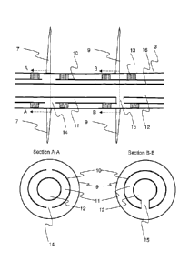
Figure 3 illustrates a section of a tubular in a horizontal well 3 that has
previously been
subjected to a hydraulic fracturing process. The hydraulic fracturing process
has
induced fractures 7, 9 in the surrounding formation. The tubular is provided
with an
outer casing 10 that encloses a first fluid conduit 11 and a second fluid
conduit 12.
Packers 13 are used to isolate different sections of the tubular within the
well, and
packers are located either side of a fracture 7, 9 in order to isolate the
fracture 7, 9
from a gap between the well 3 and the casing 10. Pairs of packers 13 may be
used,
but it will be appreciated that only one packer is necessary to isolate the
first fluid
conduit 11 from the second fluid conduit 12.
Some of the fractures 7 (termed herein "production fractures") are used to
allow
hydrocarbons to migrate towards the tubular, and other fractures 9 (termed
herein
"injection fractures") are used for injecting high pressure fluid. The casing
10 has a first
opening 14 that provides a fluid connection between the well 3 and the first
fluid
conduit 11. These openings are substantially aligned with the production
fractures 7.
The casing 10 has a second opening 15 that provides a fluid connection between
the
well 3 and the second fluid conduit 12. It will be appreciated that a
horizontal section of
the well will typically be provided with many such openings 14, 15.
In normal production, produced hydrocarbons migrate along the production
fractures 7,
through the first opening 14 and into the first fluid conduit 11 such that the
first fluid
conduit 11 carries produced hydrocarbons. The first opening 14 may be provided
with
known filters and sand screens, such as those used with existing production
tubulars.
If required, the second opening 15 may also be provided with filters and sand
screens.
Furthermore, the first opening 14 may be provided with a valve (not shown)
that can
autonomously shut off gas or water in the event of a breakthrough. An example
of
such as valve is described in WO 2008/004875, but it will be appreciated that
any other
type of valve may be used to control the flow of fluids into the first fluid
conduit 11. The
first opening 14 is disposed in a section of the casing 10 that is located
between two
packers 13 in order to isolate the first opening 14 in the well 3.
In normal production, the second fluid conduit 12 carries high pressure
injection fluid,
typically provided from a production facility 4. The injection fluid passes
through the
second fluid conduit 12 and through the second opening 15. As the second
opening 15
is also isolated in the well by a pair of packers 13, and is disposed adjacent
to an
CA 02907623 2015-09-21
WO 2014/147226
PCT/EP2014/055716
9
injection fracture 9, the high pressure injection fluid passes into the
injection fracture.
The second opening 15 may also be provided with a valve to control the volume
and
rate of injection fluid passing through the second opening 15.
A purpose of having a pair of packers 13 isolating the first opening 14 and a
further pair
of packers 13 isolating the second opening is to ensure that there is no
direct fluid
connection between the first conduit 11 and the second conduit 12. This would
otherwise lead to a "short circuit" in which high pressure injection fluid
could travel
along the well 3 and enter the first fluid conduit 11.
In an embodiment, the openings 14, 15 are aligned such that each first opening
14 is
adjacent along the length of the tubular to a second opening 15 on either side
of the
first opening 14. This has the effect of making every other fracture a
production
fracture 7, with injection fractures 9 between each production fracture 7.
This leads to
improved hydrocarbon recovery because high pressure injection fluid (typically
a gas)
passes into the injection fractures 9 and increases the pressure in the
formation. This
causes hydrocarbons in the shale formation located between fractures to move
towards production fractures 7, and therefore enhances hydrocarbon recovery
from the
formation. Maintaining the pressure in the formation using the injection
fractures 9
increases the production rate of hydrocarbons.
The use of simultaneous injection and production maintains pressure in the low
permeability formation and forces hydrocarbons towards the production
fractures. This
technique therefore increases the hydrocarbon production rate significantly
compared
to a scenario in which no injection is applied. This differs from steam
injection in known
steam assisted gravity drainage (SAGD) techniques. For example, the disclosure
of
WO 2010/092338 describes techniques to lower the viscosity of heavy oils, but
makes
no mention of hydraulic fracturing or using pressure applied to injection
fractures to
"push" hydrocarbons towards production fractures.
As shown in Figure 3, in an embodiment of the invention the outer casing 10
forms an
outside wall of the first fluid conduit 11. A tubular member 16 having a
smaller
diameter than the outer casing 10 is disposed inside the outer casing 10. The
first fluid
conduit is therefore formed by an annulus defined between the outer casing 10
and the
tubular member 16. The first opening 14 between the first fluid conduit and
the well 3
CA 02907623 2015-09-21
WO 2014/147226
PCT/EP2014/055716
can be formed from an opening in the outer casing. The interior of the tubular
member
16 forms the second fluid conduit 12. In this case, the second opening 15
between the
well 3 and the second fluid conduit 12 is a passage that passes through the
annulus
defining the first fluid conduit 11 to provide a fluid connection between the
well 3 and
5 the second fluid conduit 12.
An advantage of having the second fluid conduit 12 defined by the smaller
diameter
tubular member 16 is that the smaller diameter allows a higher pressure to be
maintained in the second fluid conduit 12. However, it will be appreciated
that the
10 annulus defined by the outer casing 10 and the tubular member 16 could
be used as
the second fluid conduit 12 for carrying high pressure injection fluid, and
the interior of
the tubular member 16 could be used as the first fluid conduit for carrying
produced
hydrocarbons.
Other arrangements for providing a first fluid conduit 11 and a second fluid
conduit 12
in a single outer casing 10 are possible. Figures 4A and 4B show cross-
sections at
different points along the length of a well illustrating one such example. In
this
example, an outer casing 10a in the well 3 has a dividing wall 17 dividing the
outer
casing into two sections 11a, 12a. One section 11a acts as the first fluid
conduit, the
other section 12a acts as the second fluid conduit. A first opening 14a
provides a fluid
connection between the well 3 and the first fluid conduit 11a, and a second
opening
15a provides a fluid connection between the well 3 and the second fluid
conduit. It will
be appreciated that the openings 14a, 15a shown in Figure 4 will in practice
be offset
along the length of the well 3 such that the first opening 14a is disposed in
proximity to
a production fracture 7 and the second opening 15a is disposed in proximity to
an
injection fracture 9, and that the openings 14a, 15a will be isolated by a
pair of packers
13.
As shown in Figure 5, a further exemplary arrangement is to provide two
tubulars 17,
18, hoses or pipes in the same wellbore such that a production tubular 17 is
used for
conveying produced hydrocarbons, and an injection tubular 18 is used for
conveying
injection fluid. The openings 19 in the production tubular 17 substantially
line up with
production fractures 7 and the openings 20 in the second tubular substantially
line up
with injection fractures 9.
CA 02907623 2015-09-21
WO 2014/147226
PCT/EP2014/055716
11
In a further exemplary arrangement, otherwise compatible with the arrangements
described above, at least some of the packers are replaced with a gravelpack.
As
shown in Figure 5, gravelpack 21 performs the function of the packers of
Figure 3, in
that the gravelpack 21 restricts the flow of fluid in the annulus between the
well 3 and
the outer casing 10 (or, in the case of two tubulars, between the production
tubular 17
and the injection tubular 18). The gravelpack 21 is unlikely to completely
prevent
injection fluids from entering the first openings 14, 19 but it reduces the
flow of injection
fluids into the first openings 14, 19 to an acceptable level. Note that a
gravelpack 21
along the entire length of the tubular could be used to replace packers 13
altogether.
The use of a gravelpack 21 may be particularly suitable for the exemplary
embodiment
shown in Figure 5 in which two tubulars 17, 18 are used. The tubulars could
otherwise
be difficult to isolate using packers. The use of a gravelpack 21 also reduces
the
operational complexities in locating the packers 13, and the absence of
packers 13
also means there is no risk of a packer failure leading to injection fluids
entering the
production tubular.
Figure 5 is a flow diagram illustrating exemplary steps of fitting and
operating a
production tubular in a shale reservoir. The following numbering corresponds
to that of
Figure 5:
Si. The
well is drilled into the reservoir. It may or may not have a cemented liner
installed.
S2. Hydraulic fracturing is induced at known locations in the well. The
locations for
fractures are selected based on reservoir modelling and geomechanical
considerations
to optimize production from the well. The fractures are shown as being
oriented with a
main axis substantially perpendicular to the well, but it will be appreciated
that this is
not always necessary and in some cases may be hindered by geological
considerations. This is achieved by drilling the well in the direction of the
least
horizontal stress. An advantage of orienting fractures with a main axis
substantially
perpendicular to the well 3 is that it makes it easier to align the fractures
with fractures
from adjacent wells, as described in more detail below.
S3. The well is completed using a combined injection and production tubular
as
described above in Figure 3. The first openings 14 are located adjacent to
production
CA 02907623 2015-09-21
WO 2014/147226
PCT/EP2014/055716
12
fractures 7 and the second openings 15 may be located adjacent to injection
fractures
9, and the fractures are isolated by at least one or more packers 13 (Figure 3
shows a
pair of packers 13 around each opening, but it will be appreciated that any
number of
packers can be used if it prevents or restricts a flow of fluid between the
first and
second openings). As described above, a typical arrangement is for each
alternate
fracture to be a production fracture 7 and the fractures between the
production
fractures 7 to be injection fractures 9. Packers are disposed between the
outer casing
and the well in such a way as to isolate the first opening 14 from the second
opening 15.
S4. High pressure injection fluid is passed through the second fluid
conduit 12 and
into the injection fractures 9. This increases the pressure in the reservoir
around each
injection fracture, causing hydrocarbons in the reservoir to be pushed towards
adjacent
production fractures 7 on either side of each injection fracture.
S5. Hydrocarbons that are pushed towards the production fractures 7 pass
along
the production fractures 7 and through the first openings 14 into the first
fluid conduit
11, allowing the hydrocarbons to be produced from the well 3. Steps S4 and S5
run
simultaneously. The fluid isolation of the first fluid conduit from the second
fluid conduit
means that injection and production are performed simultaneously, and the
injection
operation enhances the production.
It will not always be possible to line up the production fractures 7 and the
injection
fractures 9 from each well 3, 18 as shown. However, even if this alignment
cannot be
achieved, production of hydrocarbons is still enhanced. The first 3 and second
8 wells
may be disposed substantially side by side or above and below one another.
Turning now to Figure 8, there is illustrated a further method that addresses
the above
problem. The following numbering corresponds to that of Figure 8:
S6. The well is drilled into the reservoir. It may or may not have a
cemented liner
installed.
S7. The well is completed using a combined injection and production tubular
as
described above. The first openings 14 are located adjacent to production
fractures 7
CA 02907623 2015-09-21
WO 2014/147226
PCT/EP2014/055716
13
and the second openings 15 may be located adjacent to injection fractures 9,
and the
fractures are isolated by at least one or more packers 13 (Figure 3 shows a
pair of
packers 13 around each opening, but it will be appreciated that any number of
packers
can be used if it prevents or restricts a flow of fluid between the first and
second
openings). As described above, a typical arrangement is for each alternate
fracture to
be a production fracture 7 and the fractures between the production fractures
7 to be
injection fractures 9.
S8. Hydraulic fracturing is induced at known locations in the well. The
locations for
fractures are selected based on reservoir modelling and geomechanical
considerations
to optimize production from the well. Hydraulic fracturing may be performed
using both
the first openings 14 and the second openings 15. This ensures that during
subsequent simultaneous injection and production, the induced fractures are
substantially aligned with the first openings 14 and second openings 15, and
eliminates
the need to align the openings with the fractures during a subsequent
completion
operation.
S9. High pressure injection fluid is passed through the second fluid
conduit 12 and
into the injection fractures 9. This increases the pressure in the reservoir
around each
injection fracture, causing hydrocarbons in the reservoir to be pushed towards
adjacent
production fractures 7 on either side of each injection fracture.
S10. Hydrocarbons that are pushed towards the production fractures 7 pass
along
the production fractures 7 and through the first openings 14 into the first
fluid conduit
11, allowing the hydrocarbons to be produced from the well 3. Steps S9 and S10
occur
simultaneously. The fluid isolation of the first fluid conduit from the second
fluid conduit
means that injection and production are performed simultaneously, and the
injection
operation enhances the production.
The use of a combined injection/production tubular to allow continuous
injection of high
pressure fluids into a reservoir at the same time as producing hydrocarbons
that are
moved by the increased pressure can significantly increase the hydrocarbon
recovery
and production rate in certain reservoirs. This type of system is particularly
suitable to
reservoirs in low porosity, low permeability formations that use hydraulic
fracturing. It
CA 02907623 2015-09-21
WO 2014/147226
PCT/EP2014/055716
14
may be used in other types of reservoirs provided there is sufficient porosity
to allow
efficient high pressure fluid injection.
It will be appreciated by a person of skill in the art that various
modifications may be
made to the embodiments described above without departing from the scope of
the
present disclosure.
In an alternative embodiment, there is provided a method of completing a well
for
producing hydrocarbons from a low permeability reservoir formation. A wellbore
is
drilled into the low permeability reservoir formation. A hydraulic fracturing
operation is
performed to induce a plurality of fractures in the reservoir at known
locations. Each
fracture is designated as either one of a first set of fractures or one of a
second set of
fractures. The well is completed using a first fluid conduit arranged to
transport
produced hydrocarbons and a second fluid conduit arranged to transport an
injection
fluid. A set of first openings is provided in fluid connection with the first
fluid conduit,
each first opening being located to substantially align with one of the first
set of
fractures. A set of second openings is provided in fluid connection with the
second
fluid conduit, each second opening being located to substantially align with
one of the
second set of fractures. This allows, in use, injection fluid to be applied to
the second
set of fractures which increase the pressure in the formation and pushes
hydrocarbons
towards the first set of fractures, making hydrocarbons easier to produce.
A valve may be provided to at least some of the first set of openings, the
valve
arranged to control a flow of hydrocarbons into the first fluid conduit. This
allows flow
to be controlled or substantially shut of in the event of an unwanted water or
gas
breakthrough. Valves may also be provided to at least some of the second set
of
openings, the valve arranged to control a flow of injection fluid from the
second fluid
conduit. An advantage of this is that, in use, the valves can maintain a
similar pressure
and/or flow rate of injection fluid into the second set of fractures along the
length of the
well, to maintain an even pressure of injection fluid in the low permeability
formation.
A packer may be disposed in proximity to the first set of openings and a
further packer
is disposed in proximity to the second set of openings. The packers are
arranged to
ensure no fluid connection between the first set of openings and the second
set of
openings. In some circumstances, a gravelpack is optionally used instead of
packers.
CA 02907623 2015-09-21
WO 2014/147226
PCT/EP2014/055716
While the gravelpack may not ensure that there is no fluid connection between
the first
and second sets of openings, it will restrict the flow of fluids between the
first and
second sets of openings and this may be within acceptable levels.
5 An example of a low permeability reservoir formation is a shale
formation.
The first set of fractures and the second set of fractures may be disposed
along a main
axis of the well such that a fracture of the first set of fractures alternates
with a fracture
of the second set of fractures. This allows more even distribution of pressure
from the
10 injection fluid within the well and ensures that as much of the
reservoir as possible can
be subject to pressure from the injection fluid to increase hydrocarbon
production.
The first fluid conduit and the second fluid conduit may be disposed in a
tubular
comprising an outer casing, and the first set of openings and the second set
of
15 openings are located in the outer casing. In this case, the second fluid
conduit may
form an inner conduit, and the first fluid conduit may be formed in the
annulus between
the second fluid conduit and the outer casing. An advantage of having the
second fluid
conduit as the inner conduit is that it has a smaller diameter and can
therefore more
easily maintain the high pressure required for the injection fluid.
In this embodiment, a well in a low permeability reservoir formation is
provided with a
plurality of hydraulic fractures, each fracture being designated as one of a
first set of
fractures and a second set of fractures. An injection fluid is injected into
at least one of
the second set of fractures to increase a pressure in the low permeability
reservoir.
Hydrocarbons are simultaneously produced from at least one of the first set of
fractures
such that the hydrocarbons flow into a production tubular. The flow of
hydrocarbons
into the production tubular may be controlled using a valve to limit gas or
water
breakthrough. A flow of injection fluid may be controlled using a further
valve. This
allows a substantially uniform flow rate and/or pressure to be injected to all
of the
second set of fractures. At least one packer may be provided in proximity to
an
opening of the first set of openings, and a further packer is disposed in
proximity to an
opening of the second set of openings. The use of packers ensures that there
is no
fluid connection between the first set of openings and the second set of
openings. It
will be appreciated that the steps of injecting an injection fluid and
producting
hydrocarbons may occur simultaneously or sequentially.
CA 02907623 2015-09-21
WO 2014/147226
PCT/EP2014/055716
16
In this embodiment, a tubular for producing hydrocarbons from a low
permeability
reservoir formation is provided with an outer casing, a first fluid conduit
arranged to
transport produced hydrocarbons, a second fluid conduit arranged to transport
an
injection fluid, a first opening in the outer casing in fluid connection with
the first fluid
conduit, and a second opening in the outer casing in fluid connection with the
second
fluid conduit. The first fluid opening may further comprise a valve, the valve
arranged
to control a flow of hydrocarbons into the first fluid conduit. This reduces
the risk of
water or gas being produced in the event of a water or gas breakthrough. The
second
fluid opening may comprises a second valve, the second valve arranged to
control a
flow of injection fluid out of the second fluid conduit. This allows even
distribution of
injection fluid into the formation at all points along the length of the well.
The tubular
may be provided with a first packer disposed in proximity to the first opening
and a
second packer disposed in proximity to the second opening, wherein the packers
are
arranged to ensure no fluid connection between the first opening and the
second
opening, thereby reducing the risk of injection fluid entering the first fluid
conduit.
In this embodiment, a system comprises a wellbore in the low permeability
reservoir
formation. The wellbore has plurality of fractures in the formation induced by
hydraulic
fracturing at known locations. A first fluid conduit is located in the
wellbore and
arranged to transport produced hydrocarbons. A second fluid conduit is located
in the
wellbore and arranged to transport an injection fluid. A set of first openings
is provided
in fluid connection with the first fluid conduit, each first opening being
located to
substantially align with one of a first set of fractures. A set of second
openings is
provided in fluid connection with the second fluid conduit, each second
opening being
located to substantially align with one of a second set of fractures. This
system allows
high pressure fluid to be injected into the second set of fractures, which
pushes
hydrocarbons located in the low permeability reservoir towards the first set
of fractures,
thereby increasing the recovery rate of hydrocarbons in the low permeability
reservoir.
The first fluid conduit and the second fluid conduit may be disposed in a
tubular
comprising an outer casing, and the first set of openings and the second set
of
openings are located in the outer casing. The system may include valves
located at at
least some of the first set of openings. The valves are arranged to control a
flow of
hydrocarbons into the tubular and reduce the effects of a gas or water
breakthrough.
Similary, the system may include valves located at at least some of the second
set of
CA 02907623 2015-09-21
WO 2014/147226
PCT/EP2014/055716
17
openings, the valve arranged to control a flow of injection fluid from the
tubular. This
ensures an even flow rate/pressure of injection fluids at all points along the
length of
the well. The system may be provided with at least one packer disposed in
proximity to
each opening of the first set of openings and a further packer disposed in
proximity to
each opening of the second set of openings, wherein the packers are arranged
to
ensure no fluid connection between the first set of openings and the second
set of
openings. This ensures that injection fluid does not enter the first fluid
conduit.
It is also possible to provide a second wellbore in the low permeability
reservoir
formation. The second wellbore has a plurality of fractures induced by
hydraulic
fracturing at known locations, and the second wellbore is located adjacent to
the
wellbore. A fracture of the plurality of fractures of the wellbore may
substantially align
with a fracture of plurality of fractures of the second wellbore. This
improves the
efficiency of recovery of hydrocarbons, as pressure is uniformly applied to
the low
permeability reservoir formation.