Note: Descriptions are shown in the official language in which they were submitted.
CA 02907671 2015-09-17
WO 2014/165324
PCT/US2014/031229
METHODOLOGIES FOR MANUFACTURING SHORT MATRIX BITS
RELATED APPLICATIONS
[0001] The present application is a non-provisional application of and
claims
priority under 35 U.S.C. 119 to U.S. Provisional Application No. 61/807,651,
entitled "Methodologies for Manufacturing Short Matrix Bits" and filed on
April 2,
2013, the entirety of which is incorporated by reference herein.
BACKGROUND
[0002] This invention relates generally to drill bits used in downhole
drilling.
More particularly, this invention relates to a matrix drill bit, such as a
tungsten carbide
matrix drill bit, having an overall reduced bit height and the methods for
manufacturing the same.
[0003] Underground drilling, such as gas, oil, or mining, generally
involves
drilling a borehole through a formation deep in the earth. Such boreholes are
formed
by connecting a drill bit to long sections of pipe, referred to as a "drill
pipe," so as to
form an assembly commonly referred to as a "drill string." The drill string
extends
from the surface, to the bottom of the borehole. The drill string is rotated,
which
causes the drill bit to be rotated. As the drill bit rotates, it advances into
the earth,
thereby forming the borehole. Oftentimes, the trajectory of borehole is
directed by
steering the drill bit either towards a target or away from an area where the
drilling
conditions are difficult. The process of drilling a borehole which is directed
is
referred to as "directional drilling." A directional drilling tool generally
sits behind a
drill bit and forward of measurement tools. The directional drilling tool
facilitates
guiding the direction at which the drill bit proceeds as it moves further
within the
earth. Drilling operators have been trying to increase the ease and control of
drill bit
steerability, oftentimes with respect to changes or improvements being made to
the
directional drilling tool.
[0004] Figure 1 shows a perspective view of a matrix drill bit 100 in
accordance with the prior art. Referring to Figure 1, the matrix drill bit
100, or drill
bit, includes a bit body 110 that is coupled to a shank 115, or an upper
section. The
shank 115 includes a threaded connection 116 at one end 120 of the matrix
drill bit
100. The threaded connection 116 couples to a drill string (not shown) or some
other
- 1 -
CA 02907671 2015-09-17
WO 2014/165324
PCT/US2014/031229
equipment that is coupled to the drill string. The threaded connection 116 is
shown to
be positioned on the exterior surface of the one end 120. This positioning
assumes
that the matrix drill bit 100 is coupled to a corresponding threaded
connection located
on the interior surface of a drill string. However, the threaded connection
116 at the
one end 120 is alternatively positioned on the interior surface of the one end
120 if the
corresponding threaded connection of the drill string is positioned on its
exterior
surface in other exemplary embodiments. A bore (not shown) is formed
longitudinally through the shank 115 and the bit body 110 for communicating
drilling
fluid from within the drill string to a drill bit face 111 via one or more
nozzles 114
formed in the drill bit face 111 during drilling operations.
[0005] The bit body 110 includes a plurality of blades 130 extending from
the
drill bit face 111 of the bit body 110 towards the threaded connection 116.
The drill
bit face 111 is positioned at one end of the bit body 110 furthest away from
the shank
115. The plurality of blades 130 form the cutting surface of the matrix drill
bit 100.
One or more of these plurality of blades 130 are either coupled to the bit
body 110 or
are integrally formed with the bit body 110. A junk slot 122 is formed between
each
consecutive blade 130, which allows for cuttings and drilling fluid to return
to the
surface of the wellbore (not shown) once the drilling fluid is discharged from
the
nozzles 114. A plurality of cutters 140 are coupled to each of the blades 130
and
extend outwardly from the surface of the blades 130 to cut through earth
formations
when the matrix drill bit 100 is rotated during drilling. The cutters 140 and
portions
of the bit body 110 deform the earth formation by scraping and/or shearing.
The
cutters 140 and portions of the bit body 110 are subjected to extreme forces
and
stresses during drilling which causes surface of the cutters 140 and the bit
body 110 to
eventually wear. Although one example of the matrix drill bit has been
described,
other matrix drill bits known to people having ordinary skill in the art are
applicable
to present invention described below.
[0006] Figure 2 shows a side view and a partial cross-sectional view of
the
matrix drill bit 100 illustrating the internal components of the bit body 110
and the
coupling between the bit body 110 and the shank 115 in accordance with the
prior art.
Referring to Figures 1 and 2, the bit body 110 further includes a blank 224
and a
matrix 235 bonded to the blank 224. The matrix 235 defines a bore 240 therein
and a
plurality of passageways 245 extending from the bore 240 to the respective
nozzle
114 in the drill bit face 111. The bore 240 of the bit body 110 is fluidly
- 2 -
CA 02907671 2015-09-17
WO 2014/165324
PCT/US2014/031229
communicable with the bore of the shank 115 once the shank 115 is coupled to
the bit
body 110.
[0007] The blank 224 is a cylindrical steel casting mandrel that extends
into
the matrix 235. A portion of the blank 224 is positioned external to the
matrix 235
while a remaining portion of the blank 224 extends centrally and
longitudinally into
the matrix 235 and surrounds the bore 240 formed within the matrix 235.
According
to the prior art, the blank 224 is generally fabricated from AISI 1020 steel.
The blank
224, according to at least some of the prior art, includes a first portion
225, a second
portion 226, a third portion 227, and a fourth portion 228. The first portion
225 is
positioned external to the matrix 235 and includes threads 220 formed along
the outer
perimeter. However, in some alternative embodiments, the threads 220 are
formed
internally of the first portion 225. The second portion 226 also is positioned
external
to the matrix 235 and immediately adjacent to the matrix 235 between the first
portion
225 and the matrix 235. The internal diameter of the first and second portions
225,
226 are similar while the outer diameter of the second portion 226 is greater
than the
outer diameter of the first portion 225. A top end of the second portion 226
is formed
with a half-U shaped groove 231, via machining or in a mold. The third portion
227
is disposed within the matrix 225 and is positioned adjacent the second
portion 226.
The third portion 227 has an internal diameter similar to the internal
diameters of the
first and second portions 225, 226; however, the external diameter of the
third portion
227 is variable as it transitions from the outer diameter of the second
portion 226 to
the outer diameter of the fourth portion 228. The fourth portion 228 is
disposed
within the matrix 235 and extends from the third portion 227 towards the bit
face 111.
The outer diameter of the fourth portion 228 is smaller than the outer
diameter of the
second portion 226 but larger than the outer diameter of the first portion
225. Further,
the inner diameter of the fourth portion 228 is larger than the internal
diameter of the
first, second, and third portions 225, 226, 227.
[0008] The matrix 235 is formed from a sintering process and is
fabricated
from tungsten carbide powder and a binder material, such as cobalt, copper,
cobalt
alloy, copper alloy, or any other known material, such as a nickel or nickel
alloy.
Although tungsten carbide powder is used to form the matrix 235, other carbide
powders can be used in lieu of or in conjunction with the tungsten carbide
powder.
The matrix 235 bonds to the blank 224 during a sintering process and surrounds
the
third and fourth portions 227, 228 of the blank 225.
- 3 -
CA 02907671 2015-09-17
WO 2014/165324
PCT/US2014/031229
[0009] The shank 115 further includes a second end 260 positioned
distally
away from the one end 120 of the matrix drill bit 100 and a plurality of bit
breaker
slots 270 formed at opposite sides thereof between the one end 120 and the
second
end 260. The second end 260 includes threads 262 formed internally therein and
extending from the second end 260 towards the one end 120. The threads 262 are
configured to be coupled threadedly with the threads 220 of the blank 224. The
second end 260 is formed with a half-U shaped groove 261, via machining or
molding, such that a U-shaped groove 265 is formed between the shank 115 and
the
blank 224 when the shank 115 is threadedly coupled to the blank 224 and the
half U-
shaped groove 231 of the blank 224 is positioned adjacent the half U-shaped
groove
261 of the shank 115. The U-shaped groove 265 is formed with a 0.200 inch
radius
and a fifteen (15) degree angle; however, these dimensions may vary on other
examples. According to the prior art, the shank 115 is generally fabricated
from AISI
4140 steel.
[0010] In the prior art, the AISI 4140 shank 115 is welded by submerged
arc
welding ("SAW") to the AISI 1020 blank 224 forming a U-groove joint 267 within
the U-shaped groove 265. The U-shaped groove 265 allows access to the root of
the
weld when performing welding using the SAW weld technique, which is known to
people having ordinary skill in the art and is not repeated herein for the
sake of
brevity. The U-shaped groove 265 is filled with multiple passes using the SAW
weld
technique, thereby forming the U-groove joint 267. The SAW welding technique
makes use of a 0.062 inch diameter wire, Lincolnweld L61 consumable electrode
material immersed in a protective layer of Lincoln 860 Flux. Since the U-
groove joint
267 is a wide joint, the overall bit height of the matrix drill bit 100
becomes longer. A
longer overall matrix bit height causes steerability of the matrix drill bit
100 to be
more difficult and/or less efficient than if a shorter overall bit height were
to be used.
BRIEF DESCRIPTION OF THE DRAWINGS
[00 1 1 ] The foregoing and other features and aspects of the invention
will be
best understood with reference to the following description of certain
exemplary
embodiments of the invention, when read in conjunction with the accompanying
drawings, wherein:
[0012] Figure 1 shows a perspective view of a matrix drill bit in
accordance
with the prior art;
- 4 -
CA 02907671 2015-09-17
WO 2014/165324
PCT/US2014/031229
[0013] Figure 2 shows a side view and a partial cross-sectional view of
the
matrix drill bit of Figure 1 illustrating the internal components of the bit
body and the
coupling between the bit body and the shank in accordance with the prior art;
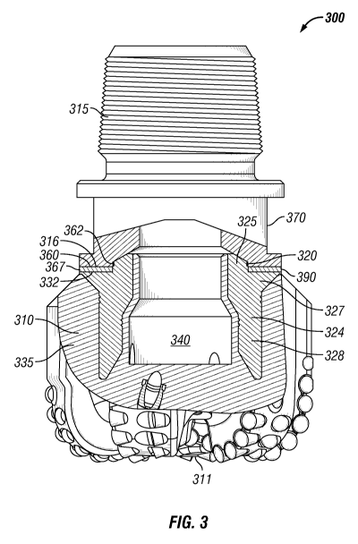
[0014] Figure 3 shows a side view and a partial cross-sectional view of a
matrix drill bit illustrating the internal components therein and the coupling
between
the bit body and the shank in accordance with an exemplary embodiment of the
present invention; and
[0015] Figure 4 shows a side view and a partial cross-sectional view of a
matrix drill bit illustrating the internal components therein and the coupling
between
the bit body and the shank in accordance with another exemplary embodiment of
the
present invention.
[0016] The drawings illustrate only exemplary embodiments of the
invention
and are therefore not to be considered limiting of its scope, as the invention
may
admit to other equally effective embodiments.
DETAILED DESCRIPTION OF THE INVENTION
[0017] This invention relates generally to drill bits used in downhole
drilling.
More particularly, this invention relates to a matrix drill bit, such as a
tungsten carbide
matrix drill bit, having a reduced bit height and the methods for
manufacturing the
same. A matrix drill bit having a reduced distance from the cutters to the
bend and/or
from the cutters to the operative portion of the steering tool allows easier
steering of
the bit through a formation. Although the description provided below is
related to a
matrix drill bit, exemplary embodiments of the invention relate to any
downhole tool
including, but not limited to, rotary bits and shear bits, that benefit from
having a
reduced overall height.
[0018] Figure 3 shows a side view and a partial cross-sectional view of a
matrix drill bit 300 illustrating the internal components therein and the
coupling
between the bit body 310 and the shank 315 in accordance with an exemplary
embodiment of the present invention. Referring to Figure 3, the matrix drill
bit 300 is
similar to matrix drill bit 100 (Figures 1 and 2) except for a portion of the
shank 315,
a portion of a blank 324, and a joint 367 coupling the blank 324 to the shank
315.
The joint 367 is a butt-weld joint according to some exemplary embodiments,
while it
is a brazed joint according to other alternative exemplary embodiments. Hence,
the
remaining features of the matrix drill bit 300, which is similar to those
corresponding
- 5 -
CA 02907671 2015-09-17
WO 2014/165324
PCT/US2014/031229
features of the matrix drill bit 100 (Figure 1), is not repeated herein for
the sake of
brevity.
[0019] According to certain exemplary embodiments, the blank 324 is a
cylindrical steel casting mandrel, or a mandrel fabricated from other suitable
material,
that extends into a matrix 335, similar to the matrix 235 (Figure 2). A
portion of the
blank 324 is positioned external to the matrix 335 while a remaining portion
of the
blank 324 is positioned centrally and longitudinally within the matrix 335 and
surrounds a bore 340, similar to bore 240 (Figure 2), formed within the matrix
335.
The blank 324 is generally fabricated from AISI 1020 steel, but is fabricated
from any
other suitable material that is bondable, or made to be bondable, with the
matrix 335
during a sintering process. According to certain exemplary embodiments, the
blank
324 includes a first portion 325, an optional second portion (not shown), a
third
portion 327, and a fourth portion 328.
[0020] The first portion 325 is positioned external to the matrix 335 and
includes threads 320 formed along the outer perimeter. The first portion 325
is
similar to first portion 225 (Figure 2), but is shorter in height than the
first portion 225
(Figure 2) in certain exemplary embodiments. Hence, there also are fewer
threads
320 in the first portion 325 than in the first portion 225 (Figure 2).
Alternatively, the
heights of both the first portion 325 and the first portion 225 (Figure 2) are
about the
same.
[0021] The optional second portion, when formed, also is positioned
external
to the matrix 335 and immediately adjacent to the matrix 335 between the first
portion
325 and the matrix 335. The internal diameter of the first and optional second
portions 325, when formed, are similar while the outer diameter of the
optional
second portion is greater than the outer diameter of the first portion 325.
The optional
second portion is similar to the second portion 226 (Figure 2), but is shorter
in height
than the second portion 226 (Figure 2). At least a portion of the top end of
the
optional second portion, when formed, is formed with a substantially flat,
planar
surface, via machining or molding. Thus, when the optional second portion is
formed, the substantially flat, planar surface of the second portion, or top
end of the
second portion, is positioned adjacently in contact, face-to-face, with a
bottom end of
the shank 315, which also is formed with a substantially flat, planar surface,
as is
further described below. As shown in Figure 3, the optional second portion is
not
formed in that exemplary embodiment.
- 6 -
CA 02907671 2015-09-17
WO 2014/165324
PCT/US2014/031229
[0022] The third portion 327 is disposed within the matrix 325 and is
positioned adjacent the optional second portion when formed, similar to the
third
portion 227 (Figure 2) and the second portion 226 (Figure 2). The third
portion 327
has an internal diameter similar to the internal diameters of the first and
optional
second portions 325 (when formed); however, the external diameter of the third
portion 327 is variable as it transitions from the outer diameter of the
optional second
portion 326 (when formed) to the outer diameter of the fourth portion 328.
When the
optional second portion is not formed as shown in Figure 3, the third portion
327 is
formed in a similar manner and includes an outer diameter that extends from
the outer
diameter of the fourth portion 328 outwardly an angle towards the upper
surface of
the matrix 335. Accordingly, in these exemplary embodiments, a top surface of
the
third portion 327 is formed with a substantially flat, planar surface 332, via
machining
or molding. Thus, when the optional second portion is not formed, the
substantially
flat, planar surface 332 of the third portion 327, or top surface of the third
portion
327, is positioned adjacently in contact with a bottom end of the shank 315,
which
also is formed with a substantially flat, planar surface, as is further
described below.
According to some exemplary embodiments, the top surface of the third portion
327 is
positioned external to the matrix 335.
[0023] The fourth portion 328 is disposed within the matrix 335 and
extends
from the third portion 327 towards the bit face 311, which is similar to bit
face 111
(Figure 1). The outer diameter of the fourth portion 328 is smaller than the
outer
diameter of the optional second portion (when formed) but larger than the
outer
diameter of the first portion 325. Further, the inner diameter of the fourth
portion 328
is larger than the internal diameter of the first, optional second, and third
portions
325, 327.
[0024] The matrix 335 is formed from a sintering process and is
fabricated
from tungsten carbide powder and a binder material, such as cobalt, copper,
cobalt
alloy, copper alloy, or any other known material, such as a nickel or nickel
alloy.
Although tungsten carbide powder is used to form the matrix 335, other carbide
powders can be used. The matrix 335 bonds to the blank 324 during a sintering
process and surrounds the third and fourth portions 327, 328 of the blank 325.
[0025] The shank 315 is similar to shank 215 (Figure 2) except that shank
315
includes a second end 360 configured to be coupled to the blank 324.
Optionally, the
shank 315 also includes a plurality of bit breaker slots 370 formed at
opposite sides
- 7 -
CA 02907671 2015-09-17
WO 2014/165324
PCT/US2014/031229
thereof, similar to bit breaker slots 270 (Figure 2). The second end 360
includes
threads 362 formed internally therein and configured to be coupled threadedly
with
the threads 320 of the first portion 325 of the blank 224. The second end 360
is
formed, via machining or molding, with a substantially flat, planar surface
316, such
that surface 316 and surface 332 (or surface of second portion when used) are
face-
to-face and form a gap 390 therebetween measuring about 0.002 inches or less.
In
other exemplary embodiments, this gap 390 may be larger but accommodates a
butt-
weld joint 367 or a brazed joint 367 being formed therebetween. According to
certain
exemplary embodiments, the shank 315 is generally fabricated from AISI 4140
steel,
but can be fabricated from any suitable material.
[0026] According to the exemplary embodiment illustrated in Figure 3, the
second end 360 of the shank 315 is threadedly coupled to the first portion 325
of the
blank 324. Once threadedly coupled together, the surface 316 of the shank 315
is
positioned face-to-face with the surface 332 of the third portion 327 of the
blank 324
forming the gap 390 therebetween measuring about 0.002 inches or less. A butt-
weld
joint 367 is formed within this gap 390 to weldedly couple the shank 315 to
the blank
324, thereby forming the matrix drill bit 300 having a reduced overall height
than
compared to the prior art matrix drill bit 100 (Figure 1). This butt-weld
joint 367 is
formed using a "keyhole" welding process using plasma arc welding ("PAW") or
other deep penetration, narrow, minimal HAZ welding process including, but not
limited to, electron beam welding ("EBW"), laser beam welding ("LBW"), inertia
welding ("IW"), or other welding process, which are described in further
detail below.
Alternatively, a thin, braze joint 367 is formed in the gap 390 via induction,
torch, or
vacuum furnace brazing to couple the shank 315 to the blank 324, which is
described
in further detail below.
[0027] Although not illustrated in exemplary embodiment of Figure 3, the
blank 324 can include the optional second portion such that the second end 360
of the
shank 315 is threadedly coupled to the first portion 325 of the blank 324 and
once
threadedly coupled together, the surface 316 of the shank 315 is positioned
face-to-
face with the surface (not shown) of the optional second portion of the blank
324
forming a gap (not shown) therebetween measuring about 0.002 inches or less. A
butt-weld joint or a thin, brazed joint is formed within this gap, as
mentioned above,
to weldedly or brazedly couple the shank 315 to the blank 324, thereby forming
the
- 8 -
CA 02907671 2015-09-17
WO 2014/165324
PCT/US2014/031229
matrix drill bit 300 having a reduced overall height than compared to the
prior art
matrix drill bit 100 (Figure 1).
[0028] Some of the welding process suited for welding a butt joint are
electron
beam welding, laser beam welding, plasma arc welding, or inertia welding. In
plasma
arc welding of certain thicknesses of base metals, "keyhole welding" is
performed
using special combinations of plasma gas flow, arc current, and weld travel
speed. In
the keyhole welding process, a relatively small weld pool with a hole, passes
completely through the base metal, and is referred to as a "keyhole". The
plasma arc
process is the only gas shielded welding process with this capability. In a
stable
keyhole operation, molten metal is displaced to the top bead surface by the
plasma
stream (in penetrating the weld joint) to form the characteristic keyhole. As
the
plasma torch is moved along the weld joint, metal melted by the arc is forced
to move
around the plasma stream and to the rear where the weld pool is formed and
solidified. This flow of molten metal and the complete penetration of the
metal
thickness allows the impurities to flow to the surface and the gasses to be
expelled
more readily before solidification. The maximum weld pool volume and the
resultant
root surface profile are largely determined by the effects of a force balance
between
the molten weld metal surface tension and the plasma stream velocity
characteristics.
The high current keyhole technique of welding operates at conditions just
below
conditions that would actually cut through the metals, rather than weld the
metals
together. For cutting, a slightly higher orifice gas velocity blows the molten
metal
away. In welding, the gas velocity is just low enough that the surface tension
of the
molten metal hold it in the joint instead of blowing the molten metal out the
bottom,
as performed when cutting. Therefore orifice gas flow rates for welding are
critical
and are closely controlled. Variation of no more than 0.12 liters per minute
in flow
rate is the rule of thumb. Hence, the "keyhole" welding technique associated
with
welding by plasma arc welding (PAW) is implemented to achieve the deep narrow
weld necessary to join the steel blank 324 to the shank 315, or upper section.
A
"keyhole" weld by PAW into a thin butt weld joint allow achievement of an
overall
height reduction in the bit.
[0029] Alternatively, in some other exemplary embodiments, the joint 367
is
made by brazing the shank 315, or upper section, to the steel blank 324 using
any
number of brazing process including, but not limited to, torch brazing,
induction
brazing, or vacuum furnace brazing, using a copper, silver, or nickel based,
or other
- 9 -
CA 02907671 2015-09-17
WO 2014/165324
PCT/US2014/031229
suitable braze filler metal. For example, the shank 315 and the steel blank
324 are
screwed together and held in place for the brazing process. According to
certain
exemplary embodiments, tackwells (not shown) are used to hold these components
in
place; however, other components are used in other exemplary embodiments. A
filler
material is applied in the gap formed between the two components. The
components
are then heated causing the filler material to flow into the gaps via
capillary action.
The components are then removed from the heat causing the filler material to
cool
down and join the two components together.
[0030] Figure 4 shows a side view and a partial cross-sectional view of a
matrix drill bit 400 illustrating the internal components therein and the
coupling
between the bit body 410 and the shank 415 in accordance with another
exemplary
embodiment of the present invention. Referring to Figure 4, the matrix drill
bit 400 is
similar to matrix drill bit 300 (Figure 3) except that the first portion 325
(Figure 3) of
the blank 324 (Figure 3) is removed from the blank 324 (Figure 3) to form a
blank
424. Hence, a third portion 427, similar to third portion 227 (Figure 3),
includes a
substantially flat, planar surface 432, which is similar to the substantially
flat, planar
surface 332 (Figure 3). Further, the second end 360 (Figure 3) of the shank
315
(Figure 3) is extended inwardly to occupy the area that previously was
occupied by
the first portion 325 (Figure 3) of the blank 324 (Figure 3), thereby forming
a second
end 460 of the shank 415. The second end 460 is similar to second end 360
(Figure 3)
and includes a substantially flat, planar surface 416. The surface 416 is
positioned
adjacently and face-to-face with the surface 4332 (or surface of second
portion when
used) to form a gap 490, which is similar to the gap 390 (Figure 3). Since the
threaded portion of the blank 424 is removed, the shank 415 cannot be
threadedly
coupled to the blank 424 and is coupled only via a joint formed in the gap
490. The
joint 467, similar to the joint 367 (Figure 3), is formed within the gap 490
pursuant to
the descriptions provided above.
[0031] Hence, a further reduction in overall bit height is achieved by
eliminating the threaded portion of the connection between the steel blank 424
and the
shank 415. The threaded connection was previously used, in the prior art, to
hold the
steel blank to the shank until the welder can lay a bead at the root of the
single U
groove. By implementing a butt joint in lieu of a single "U" groove, the
threaded
section is optional, but not necessary. The shank 415 is held steady to the
steel blank
424 using other fixturing methods.
- 10 -
CA 02907671 2015-09-17
WO 2014/165324
PCT/US2014/031229
[0032] Although the invention has been described with reference to
specific
embodiments, these descriptions are not meant to be construed in a limiting
sense.
Various modifications of the disclosed embodiments, as well as alternative
embodiments of the invention will become apparent to persons skilled in the
art upon
reference to the description of the invention. It should be appreciated by
those skilled
in the art that the conception and the specific embodiments disclosed may be
readily
utilized as a basis for modifying or designing other structures for carrying
out the
same purposes of the invention. It should also be realized by those skilled in
the art
that such equivalent constructions do not depart from the spirit and scope of
the
invention as set forth in the appended claims. It is therefore, contemplated
that the
claims will cover any such modifications or embodiments that fall within the
scope of
the invention.
- 11 -