Note: Descriptions are shown in the official language in which they were submitted.
CA 02907877 2015-09-23
WO 2014/170671 PCT/GB2014/051190
1
LOAD BEARING APPARATUS AND METHOD
FIELD OF THE INVENTION
The present invention relates to a load-bearing apparatus comprising multiple
load-bearing elements, to a traction device for use in such, and to a tension
control
apparatus for controlling the tension of each of the load-bearing elements.
BACKGROUND TO THE INVENTION
Numerous fields of application require the deployment of heavy loads to/from a
location of interest, including building, construction, mining, oil and gas,
etc. One such
application involves the deployment of sub-sea hardware in very deep water,
e.g., at
depths of 1000m and greater. Deep water deployment of sub-sea hardware is
particularly associated with the oil and gas industry. Examples of such sub-
sea
hardware include manifolds, templates, processing modules and wellhead
systems.
Assemblies of this type can weigh hundreds of tonnes. Similarly, extreme loads
may
be encountered when lifting or lowering a pipeline or section of pipeline to
or from the
seabed during installation and/or maintenance.
Deep water deployment systems including cranes employ a variety of
mechanisms and typically include traction systems to move payloads via load-
bearing
spoolable media, such as metal, synthetic or natural fibre cables, wires and
ropes.
Traction systems include a drum winch around which a spoolable medium is
wound,
wherein rotation of the drum permits spooling of the medium.
In some species of winch the drum acts to store the spoolable medium, with the
medium be arranged in single or multiple wraps and layers between end flanges
of the
drum. In such winch species, however, the spoolable medium may be subject to
significant radial crushing forces, particularly in circumstances where large
payloads
are involved and thus significant tensions are applied to the spoolable
medium.
Further, in some applications it may be necessary to store the medium in a
high
tension state, which may reduce the life span of the medium through fatigue,
excessive
strains, hysteresis and the like. Furthermore, storage of the spoolable medium
on a
drum typically requires the use of complex fleeting arrangements to ensure
that the
medium is arranged in suitable wraps and layers.
In other species of winch the drum is used only to apply a force to a
spoolable
medium, with the spoolable medium being stored separately, for example in a
basket,
on a separate spool or the like. The force applied by the drum is typically
either a
2
pulling force to pay in a spoolable medium, or a controlled releasing force to
permit
controlled paying out of a spoolable medium while under load, for example
while connected
to a payload. In such winch species, which may include capstan or windlass
winches, an
intermediate portion of a spoolable medium is wrapped around the drum a number
of times
such that an outboard side of the spoolable medium extends from the drum to
engage a
payload, and an inboard side of the spoolable medium extends to storage. Under
loaded
conditions the drum functions to reduce the tension in the spoolable medium
from a high
tension condition in the outboard side, to a lower tension condition in the
inboard side of the
spoolable medium, thus permitting the spoolable medium to be stored in a
favourable low
tension state. In view of this tension reduction functionality, such winch
species are often
called detensioning units. In use, the drum establishes a tension gradient in
the spoolable
medium, which may be defined by the capstan friction equation:
1 ¨ = ePe
T2
wherein: T1= outboard tension
T2 = inboard tension
p = co-efficient of friction between the spoolable medium and the drum or
contact surface
8 = angle of contact with the drum (e.g., one wrap is 2Tr radians)
The traction winch may include multiple sheaves over which the rope is drawn
both
to provide adequate traction and to progressively unload the rope before it is
passed to the
storage take up reel at low tension. An example of such traction winch is
disclosed in U.S.
Patent No. 6,182,915 (ODIM HOLDING ASA), in which the multiple sheaves are
separately
powered in a manner to prevent the cable from being damaged by slipping as it
unloads.
Another example is disclosed in International Patent Application Publication
No. WO
2011/121272 (PARKBURN PRECISION HANDLING SYSTEMS LTD), in which two traction
winch drums configured to rotate about respective first and second axes of
rotation which
are inclined relative to each other. The relative inclined alignment of the
first and second
axes of rotation of the drum assemblies permits the respective drum contact
surfaces to
cooperate to manipulate an associated spoolable medium to follow a predefined
path, such
as a predefined helical path.
When steel is used as a spoolable medium, the deployment of very large loads
of
the type described above requires the use of very large steel wire ropes or
cables.
Date Recue/Date Received 2020-05-06
CA 02907877 2015-09-23
WO 2014/170671 PCT/GB2014/051190
3
However, especially at great depths, the weight of the steel itself becomes a
significant
problem. Not only does this impose tremendous loads on the lifting system but
also,
beyond a certain depth, it becomes impossible to make a wire rope large enough
to
support its own weight without exceeding its safe working loads, let alone the
weight of
the equipment to which it is attached.
In order to reduce the weight of the spoolable media used in very deep water
applications, synthetic fibre ropes have been adopted. Synthetic fibre ropes
typically
exhibit near neutral buoyancy and therefore minimal added weight, even when
working
at great depths. Such ropes can be made from a variety of synthetic fibres.
Ultra High
Molecular Weight Polyethylene (UHMWPE) fibre rope has proven especially
successful
due to its high strength to weight ratio and low elongation under loads. For
example,
suitable UHMWPE fibre ropes are available under the Dyneema trademark of DSM,
The Netherlands.
Although synthetic fibre ropes offer a viable solution for deep water
deployment,
and are vastly superior to steel wire rope in many respects, they nevertheless
present
special challenges of their own, especially when used in larger diameters. In
particular,
when used with traction winches, synthetic fibre ropes typically require
larger diameter
sheave wheels than do wire ropes. A number of reasons for this may include
(among
others) the susceptibility of individual fibres to fracture when bent and also
the relative
inability of the fibre material to shed heat due to its low thermal
conductivity, which can
in turn lead to heat build-up and damage to the fibres in the core of the
rope. As a
result, it has been determined that the practical minimum "D:d" diameter ratio
for using
large synthetic fibre ropes on traction winch systems is approximately 30:1,
wherein
"D:d" represents the ratio between the diameter of the sheave wheel and the
diameter
of the rope. Current research focusing on loads of 250Te indicates that a
synthetic
fibre rope having the requisite capacity (including industry established
safety margins)
will have a diameter on the order of 140mm. Based on the minimum 30:1 ratio,
the
corresponding minimum sheave diameter is approximately 4.2m, which is very
large. A
750Te system would require a proportionately larger rope, to the point where
the
sheave wheels and associated machinery would be prohibitively large. Not only
is the
cost of such equipment very high, but it is compounded by the need to use a
larger
vessel and a larger crew, to the point where feasibility is drawn into
question.
Furthermore, very large diameter synthetic ropes present additional problems.
In particular, ropes do not scale well and suffer a loss of strength
translation efficiency
in their larger sizes. Furthermore, it has been found that, even when using
optimally-
CA 02907877 2015-09-23
WO 2014/170671 PCT/GB2014/051190
4
sized sheaves, the larger the rope the lower the number of bend cycles it is
able to
sustain before failure. Although the reasons for this are not entirely clear,
and without
wishing to be bound by theory, it is believed that this may be primarily due
to the mass
of material involved and the impact of the heat and abrasion generated by the
greater
number of crossover points within the rope structure, complicated by the
insulation
efficiency of the fibre material. Yet another difficulty is that splices or
other repairs in
large-size synthetic ropes increase diameter, which makes it very difficult
for these to
pass through the grooves of conventional sheave wheels, particularly on the
leading
sheave wheel where the rope is under extreme tension.
Systems using multi fall arrangements have been used in the past to seek to
overcome some of the limitations cited above, and have been used with both
steel wire
and fibre rope systems. However, although this technique overcomes the need
for
large diameter ropes, some limitations of this approach include reduction of
deployment speed by a factor proportionate to the number of falls in the
moving block.
This creates a significant increase in deployment time and hence results in a
high cost
impact when deploying payloads in great water depths. This also creates
difficulty
achieving sufficient speed in the lifting line when employing active heave
compensation
required for decoupling the vessel motions from the payload during deployment.
Systems using multiple separate drum winch systems with single lift lines
connected to the payload have been used with some success to overcome these
issues. However, the challenge of controlling multiple systems and balancing
high
tension loads in each of the lifting wires is a significant challenge, and the
risks
involved if precise control is not maintained between the separate winch
systems make
this technique difficult to implement.
Various arrangements of multiple ropes or cables combined with one or more
drums are disclosed in EP 1 460 025 (Strodter), US 605,937 (Turner), US
6,042,087
(Heinemann), US 4,600,086 (Yamasaki et al.), JP 11-011882 (Mitsubishi), JP 07-
196288 (Japan Steel Works), SU 412133 (Leningrad Lengidrostal), and CN
201220899
Weihua Group).
SUMMARY OF THE INVENTION
According to a first aspect of the present invention there is provided a load-
bearing apparatus comprising:
a winch apparatus; and
CA 02907877 2015-09-23
WO 2014/170671 PCT/GB2014/051190
a load-bearing spoolable medium for connecting to a load, the load-bearing
spoolable medium comprising a plurality of load-bearing elements;
wherein at least a portion of the load-bearing spoolable medium is spooled
about the winch apparatus.
5 The winch apparatus may comprise a contact surface for engaging at
least a
portion of the load-bearing medium, e.g. at least a portion of the plurality
of load-
bearing elements, e.g. at least a portion of each of the plurality of load-
bearing
elements.
The winch apparatus may be configured to control paying out and/or paying in
of the plurality of load-bearing elements. The winch apparatus may be
configured to
control paying out and/or paying in of each of the plurality of load-bearing
elements
simultaneously.
The winch apparatus may be configured to function as a detensioning device
for use in reducing tension within the load-bearing medium. As such, the winch
apparatus may comprise or define a detensioning device.
The winch apparatus may be configured as a capstan winch.
The load-bearing spoolable medium may comprise an outboard or high tension
portion, between the load and the winch apparatus.
The load-bearing spoolable medium may comprise an inboard or low tension
portion, on a side of the winch apparatus opposite the load.
The winch apparatus may comprise an outboard or high tension side, between
the load and the winch apparatus.
The winch apparatus may comprise an inboard or low tension side, on a side of
the winch apparatus opposite the load.
One or more load-bearing elements may comprise an elongate element, such
as a rope, cable, wire, or the like.
One or more load-bearing elements may comprise a multicomponent element,
such as a rope, cable, wire, or the like.
One or more load-bearing elements may comprise a synthetic fibre rope, a
metal rope such as a steel rope, or the like.
The cross-section of one or more load-bearing elements may be substantially
circular, oval, rectangular (e.g. a so-called "flat rope), or may have any
other suitable
profile.
One or more load-bearing elements may be made from a polymeric material, for
example UHMWPE such as sold under the trade names of DYNEEMA and
CA 02907877 2015-09-23
WO 2014/170671 PCT/GB2014/051190
6
SPECTRA ; a liquid crystal polyester (LCP) such as sold under the trade name
of
VECTRAN ; an aramid such as sold under the trade name TECHNORA , or blends
thereof. By such provision, the load-bearing elements may exhibit
suitable
characteristics for heavy lift applications, including robustness, very high
strength to
weight ratios, good bend fatigue and tension-tension fatigue, low levels of
elongation vs
load, appropriate levels of base material friction, and ready availability.
Load elongation of the plurality of load-bearing elements may typically be in
the
range of 0-4 A), wherein 0% may correspond to a load elongation at very low
loads,
and 4% may correspond to a load elongation at break load. Typical load
elongation
between low loads and maximum working load may be in the region of 0-1.5%.
Each of the plurality of load-bearing elements may be made substantially from
the same material, may be of a similar physical construction, and/or may be
provided
with similar coating(s). By such provision, the plurality of load-bearing
elements may
behave in similar fashion, e.g. on the contact surface of the winch apparatus.
For
example, the load-bearing elements may exhibit similar coefficients of
friction, heat
transfer properties, abrasion resistance, flexibility, or the like.
The construction of one or more of the plurality of load-bearing elements,
e.g.
ropes, may comprise a braided construction, e.g. a balanced braid, such as an
8-strand
or 12-strand braided rope structure and/or variations thereof. Such
constructions may
be advantageous in the apparatus of the present invention as they are torque
neutral
over a wide load range, can be easily spliced and repaired, and can be made in
very
long lengths.
The construction of one or more of the plurality of load-bearing elements,
e.g.
ropes, may comprise wire lay constructions. In such instance, the plurality of
load-
bearing elements may comprise an even number of elements/ropes with equal and
opposite left and right hand lay constructions. This may assist in avoiding or
reducing
any impact form torque mismatch between the individual elements/ropes.
The plurality of load-bearing elements may comprise 2-10 load-bearing
elements, typically 2-5 load-bearing elements. In one embodiment the plurality
of load-
bearing elements may comprise 3 load-bearing elements. The provision of 2-10,
e.g.
2-5, e.g. three load-bearing elements, may significantly reduce the diameter
appropriate for the winch apparatus, while maintaining the number of load-
bearing
elements relatively low to minimise difficulty of handling or risks of
malfunction
associated with a multiple rope system.
CA 02907877 2015-09-23
WO 2014/170671 PCT/GB2014/051190
7
The load-bearing medium may comprise a plurality of separate and/or distinct
load-bearing elements. It will be understood that the terms "separate and
distinct" are
not meant to limit the configuration of the load-bearing elements relative to
each other,
i.e. the load-bearing elements may be in contact, or may not be in contact,
with each
other. Thus, the terms "separate and distinct" are meant to indicate that the
load-
bearing elements each support, e.g. independently, a proportion, e.g. a
predetermined
amount or proportion of the weight of the load. By such provision, a
dimension, e.g. a
diameter, of each of the load-bearing elements may be reduced compared to a
dimension, e.g. diameter, of a corresponding single load-bearing medium that
would be
required to support the same load. One of the effects and advantages of such
reduction in diameter of the load-bearing elements is that the diameter of a
winch used
with such load-bearing elements may be reduced. Winch systems typically have
an
optimum diameter based on the diameter of the spoolable medium used.
Therefore,
reduction in the diameter of the load-bearing elements may allow significant
reduction
in the diameter of the winch apparatus, e.g. a drum thereof.
The load-bearing spoolable medium may comprises a plurality of adjacent load-
bearing elements.
The load-bearing elements may be arranged side-by-side on the winch
apparatus, e.g. on a contact surface of the winch apparatus.
The load-bearing elements may be arranged in a common plane.
The load-bearing elements may be arranged on the winch apparatus in a plane
being generally in a direction of, or parallel to, an axis, e.g. to a
rotational axis, of the
winch apparatus.
The load-bearing elements, e.g. the adjacent and/or side-by-side load-bearing
elements, may be substantially parallel to each other, e.g. when in engagement
with
the contact surface of the winch apparatus. The load-bearing elements may be
substantially parallel to each other when in engagement with the contact
surface of the
winch apparatus, in a plane substantially parallel to an axis, e.g. to an axis
of rotation,
of the winch apparatus, and/or tangential to a surface of the winch apparatus.
The load-bearing elements, e.g. an outboard portion thereof, may be
substantially parallel to each other.
The load bearing spoolable medium may define one or more turns around the
winch apparatus.
Typically, the load bearing spoolable medium may define a plurality of turns
around the winch apparatus.
8
The load-bearing elements may be provided in sequential order around or about
the
winch apparatus. A turn of a load-bearing element may be separated from an
adjacent turn
of the same load-bearing element, by the remaining load-bearing elements. Each
turn of
the load bearing spoolable medium may comprise a turn of the load-bearing
elements
provided in sequential order on the winch apparatus.
The weight of the load may be distributed amongst the plurality of load-
bearing
elements.
In one embodiment, the weight of the load may be substantially evenly
distributed
amongst the plurality of load-bearing elements.
In another embodiment, the weight of the load may be unevenly distributed
amongst
the plurality of load-bearing elements. For example, one or more load-bearing
elements
may be selected to bear a higher or lower load compared to the other load-
bearing
elements, e.g. temporarily, in order to accommodate, for example, operational
or
environmental requirements, fatigue or wear of one or more load-bearing
elements, etc.
A dimension, e.g. a diameter, of two or more load-bearing elements, may be
substantially identical.
Two or more of the plurality of load-bearing elements may have a different
dimension, e.g. diameter, from a dimension, e.g. diameter, of at least another
one or more
of the plurality of load-bearing elements.
The term "diameter" used herein is not meant to limit the profile of the load-
bearing
elements to a particular profile, such as circular in cross-section, but is
meant to refer to a
general height and/or width of a cross-section of the load-bearing elements.
The load may comprise a single load. In such instance each of the plurality of
load-
bearing elements may be configured for supporting, connecting to and/or
attaching to a
single load. By such provision, a dimension, e.g. a diameter, of each of the
load-bearing
elements may be reduced compared to a dimension, e.g. diameter, of a
corresponding
single load-bearing medium that would be required to support the same load.
This may
allow significant reduction in the diameter of a winch apparatusõ e.g. a drum
thereof, to be
used with such load-bearing elements.
The at least one load may comprise a plurality of loads. In one embodiment,
each of
the plurality of load-bearing elements may be configured for supporting,
connecting to
and/or attaching to a respective load. By such provision, the load-bearing
apparatus may
allow deployment and/or handling of multiple loads
using a
Date Recue/Date Received 2020-05-06
CA 02907877 2015-09-23
WO 2014/170671 PCT/GB2014/051190
9
single winch apparatus. This may be particularly advantageous, e.g. when a
plurality
of similarly weighed objects required to be lowered/hoisted/supported
to/from/at a given
location, for example sections of tubing or casing, manifolds, etc.
Various combinations of the above may be envisaged. For example, one of the
plurality of load-bearing elements may be connected to a load of relatively
low weight,
while several of the plurality of load-bearing elements may be connected to a
load of
relatively high weight.
The contact surface of the winch apparatus configured for engaging the load-
bearing spoolable medium and/or the plurality of load-bearing elements, may
comprise
a substantially flat surface.
The contact surface of the winch apparatus may comprise a substantially
continuous surface, e.g. a drum surface. The contact surface of the winch
apparatus
may comprise an interrupted surface, e.g. may be defined by a plurality of
support
elements, e.g. plurality of circumferentially arranged support elements which
may
collectively define a/the contact surface.
The contact surface may comprise a grooved profile, e.g. may comprise at least
one groove. In one embodiment the at least one groove may be arranged to
receive
and/or guide the load-bearing spoolable medium and/or the plurality of load-
bearing
elements on the contact surface.
The winch apparatus may comprise one or more sheaved wheels, a single
drum winch, a multiple drum winch, or the like.
The load-bearing apparatus may comprise a tension control apparatus for
controlling, applying and/or adjusting the tension of the load-bearing
spoolable medium
and/or the plurality of load-bearing elements, e.g. on an inboard or low
tension side of
the winch apparatus.
The tension control apparatus may be located on an inboard side of the winch
apparatus.
The tension control apparatus may be arranged to individually and/or
independently control, apply, and/or adjust the tension of each of the
plurality of load-
bearing elements.
The tension control apparatus may comprise at least one tension control
device.
The tension control apparatus may comprise one tension control device
capable of controlling, applying and/or adjusting the tension of each of the
plurality of
load-bearing elements.
CA 02907877 2015-09-23
WO 2014/170671 PCT/GB2014/051190
The tension control apparatus may comprise a plurality of tension control
devices, each capable of controlling, applying and/or adjusting the tension of
a
respective load-bearing element, e.g. individually and/or independently. By
such
provision, any variation in tension between load-bearing elements on an
outboard side
5 of the
winch apparatus, e.g. due to marine currents, interfering objects, rope
construction, etc, may be mitigated and/or overcome by controlling and/or
adjusting the
tension of each of the load-bearing elements on an inboard side of the winch
apparatus. This is because the tension gradient on the winch apparatus may be
defined by the capstan friction equation:
0
=
T2
wherein: T1= outboard tension
T2 = inboard tension
p = co-efficient of friction between the load-bearing element and the
drum or contact surface
e = angle of contact with the drum or contact surface (e.g., one wrap is
27 radians)
Therefore, assuming that p and e are known, T1 on the outboard side can be
controlled and/or maintained at a predetermined or desired value by
controlling and/or
maintaining T2 on the inboard side at a predetermined value.
In one embodiment, the at least one tension control apparatus may be
configured to maintain or apply substantially equal tensions between the load-
bearing
elements, e.g. when the load-bearing elements are of substantially equal
dimension,
e.g. diameter. The at least one tension control apparatus may be configured to
maintain or apply substantially equal tensions between respective outboard
portions of
the plurality of load-bearing elements. By such provision, the weight of the
at least one
load may be substantially equally distributed amongst the load-bearing
elements, thus
preventing any of the ropes from experiencing overload that may lead to
premature
failure. This may also ensure compliance within a minimum safety standards in
the
industry. Offshore lifting operations are regulated by classification society
rules and
regulations, which include for example DNV, Bureau Veritas and Lloyds
Register. All
lifting and lowering operations have to maintain a certain minimum safety
factor (SF)
within the lifting system related to a payload, the SF including not only the
weight in air
but any added mass or other dynamic factors the payload will see during
deployment.
Typical minimum SF for offshore operations is in the order of 3.5 x the
payload. Thus,
CA 02907877 2015-09-23
WO 2014/170671 PCT/GB2014/051190
11
controlling the inboard tension of each load-bearing element to maintain
substantially
equal outboard tensions between the plurality of load-bearing elements, may
assist in
complying with minimum safety regulations in a particular industry, such as
offshore
lifting operations. Another advantage may include reducing the difference in
load
elongation between the load-bearing elements, which may lead to undesirable
relative
movement or slip between the load-bearing elements on the winch apparatus.
In another embodiment, the at least one tension control apparatus may be
configured to maintain or apply different tensions between the load-bearing
elements.
The at least one tension control apparatus may be configured to maintain or
apply
different tensions between respective outboard portions and/or inboard
portions of the
plurality of load-bearing elements. This may help accommodate, for example,
operational or environmental requirements, fatigue or wear of one or more load-
bearing
elements, etc.
Various combinations of the above may be envisaged. For example, the at
least one tension control apparatus may be configured to maintain or apply
substantially equal tensions between two or more of the load-bearing elements,
and
may be configured to maintain or apply different tensions between two or more
of the
load-bearing elements.
The tension control apparatus may be arranged to maintain a difference in
tension between the load-bearing elements at a predetermined level, e.g. below
a
predetermined limit, such as below about 20%, e.g. below about 10%, e.g. below
about
5%. The tension control apparatus may be arranged to maintain a difference in
tension
between the load-bearing elements at a particular or predetermined position
relative to
the winch apparatus, e.g. on an outboard side and/or on an inboard side
thereof.
The tension control device(s) may comprise at least one drum, winch, sheave,
track system, or the like.
The load-bearing apparatus, e.g. the tension control apparatus, may comprise a
sensing device or arrangement.
The sensing device or arrangement may be arranged to sense or measure at
least one property or parameter of at least one portion of the load-bearing
apparatus.
The sensing device or arrangement may be arranged to sense or measure at least
one
property or parameter of the load-bearing spoolable medium.
The sensing device or arrangement may comprise at least one tension-
measuring device, e.g. meter, for measuring the tension of one or more load-
bearing
CA 02907877 2015-09-23
WO 2014/170671 PCT/GB2014/051190
12
elements, e.g. of the plurality of load-bearing elements, e.g. on an inboard
portion
thereof.
In one embodiment, the sensing device or arrangement may comprise a
plurality of tension-measuring devices, each capable of measuring the tension
of a
respective load-bearing element, e.g. on an inboard portion thereof.
The sensing device or arrangement may comprise a sensor associated with the
winch apparatus, e.g. a rotational sensor.
The sensing device or arrangement may comprise a sensor for measuring the
deviation or movement of the load-bearing elements on the winch apparatus,
e.g. on a
drum thereof.
The sensing device or arrangement may comprise a sensor for measuring the
length of rope provided engaging the winch apparatus, e.g. a contact surface
thereof.
By such provision, any slip of one or more load-bearing elements on the winch
apparatus, e.g. due to excessive tension, may be detected.
The load-bearing apparatus, e.g. the tension control apparatus, may comprise
at least one actuator, e.g. a tension control actuator. The at least one
actuator, e.g.
tension control actuator, may be arranged for actuating the at least one
tension control
device, or may form part of the at least one tension control device.
The at least one actuator may comprise a motor.
In one embodiment, the load-bearing apparatus, e.g. the tension control
apparatus, may comprise a plurality of actuators, each capable of actuating a
respective tension control device.
The sensing device or arrangement may be arranged to provide feedback, e.g.
to a user or operator, and/or may comprise a closed-loop control system, e.g.
a closed-
loop tension control apparatus.
The sensing device or arrangement may be provided with a display, e.g. a
graphic, alphanumeric, audio, and/or tactile display, arranged to provide
feedback, e.g.
an indication of a measurement made by the sensing device or arrangement.
The at least one actuator may be activated manually, e.g. by a user, for
example in response to a measurement made by the sensing device or
arrangement,
such as a change in tension measured by the at least one tension-measuring
device.
The at least one actuator may be activated automatically and/or may form part
of a closed-loop system, e.g. a closed-loop tension control apparatus. In one
embodiment, the at least one actuator may be associated with the at least one
tension-
measuring device, such that departure in tension from a predetermined range
may
CA 02907877 2015-09-23
WO 2014/170671 PCT/GB2014/051190
13
automatically activate the at least one actuator, and/or cause the at least
one actuator
to actuate the at least one tension control device.
The load-bearing apparatus may further comprise a storage apparatus for
storing the load-bearing medium.
The storage apparatus may be provided on an inboard side of the winch
apparatus, e.g. on an inboard side of the tension control apparatus.
The storage apparatus may comprise one or more storage devices.
In one embodiment, the storage apparatus may comprise one storage device
capable of storing the load-bearing spoolable medium, e.g. the plurality of
load-bearing
elements.
In another embodiment, the storage apparatus may comprise a plurality of
storage devices, each capable of storing a relative load-bearing element.
The storage apparatus may comprise one or more container, reel, or the like.
The load-bearing apparatus may be used in applications requiring supporting or
moving, e.g. lowering or hoisting, of a load. Such applications may comprise
subsea
applications, such as on off-shore platforms or vessels; cranes such as off-
shore on
on-land cranes; towing systems; weight, counterweight, or cantilever devices;
tension
controlling devices; or the like.
According to a second aspect of the present invention there is provided a load-
bearing apparatus comprising:
a winch apparatus; and
a load-bearing spoolable medium for connecting to a load, the load-bearing
medium comprising a plurality of load-bearing elements;
wherein at least a portion of the load-bearing spoolable medium is spooled
about the winch apparatus;
wherein the load-bearing elements are arranged side-by-side on a contact
surface of the winch apparatus.
At least a portion of the load-bearing spoolable medium may be spooled about
a contact surface of the winch apparatus.
The load-bearing medium may comprises a plurality of adjacent load-bearing
elements.
The load-bearing elements may be arranged side-by-side on the winch
apparatus, e.g. on a contact surface of the winch apparatus.
The load-bearing elements may be arranged in a common plane.
CA 02907877 2015-09-23
WO 2014/170671 PCT/GB2014/051190
14
The load-bearing elements may be arranged on the winch apparatus in a plane
being generally in a direction of an axis, e.g. of a rotational axis, of the
winch
apparatus.
The load-bearing elements, e.g. the adjacent and/or side-by-side load-bearing
elements, may be substantially parallel to each other, e.g. when in engagement
with
the contact surface of the winch apparatus. The load-bearing elements may be
substantially parallel to each other when in engagement with the contact
surface of the
winch apparatus, in a plane substantially parallel to an axis, e.g. to an axis
of rotation,
of the winch apparatus.
The features described in respect of the load-bearing apparatus according to a
first aspect of the present invention may apply in respect of the load-bearing
apparatus
according to a second aspect of the present invention, and are therefore not
repeated
here for brevity.
According to a third aspect of the present invention there is provided a winch
apparatus comprising a contact surface configured for engaging a load-bearing
spoolable medium comprising plurality of load-bearing elements arranged side-
by-side
on a contact surface of the winch apparatus.
The plurality of load-bearing elements may collectively define a load-bearing
spoolable medium.
The plurality of load-bearing elements may be adapted to support, connect to
and/or attach to a load.
The winch apparatus may be configured to control paying out and/or paying in
of the plurality of load-bearing elements. The winch apparatus may be
configured to
control paying out and/or paying in of each of the plurality of load-bearing
elements
simultaneously.
The winch apparatus may be configured to function as a detensioning device
for use in reducing tension within the load-bearing medium. As such the winch
apparatus may comprise or define a detensioning device.
The winch apparatus may be configured as a capstan winch.
The winch apparatus may comprise an outboard or high tension side, between
the load and the winch apparatus.
The winch apparatus may comprise an inboard or low tension side, on a side of
the winch apparatus opposite the load.
CA 02907877 2015-09-23
WO 2014/170671 PCT/GB2014/051190
The contact surface of the winch apparatus may be configured for engaging a
plurality of adjacent load-bearing elements.
The contact surface of the winch apparatus may be configured for engaging a
plurality of load-bearing elements which may be substantially parallel to each
other, at
5 least when in engagement with the contact surface of the winch apparatus.
The load-
bearing elements may be substantially parallel to each other when in
engagement with
the contact surface of the winch apparatus, in a plane substantially parallel
to an axis of
rotation of the winch apparatus. The load-bearing elements may be
substantially
parallel to each other on an outboard side of the winch apparatus.
10 The contact surface of the winch apparatus may comprise a
substantially flat
surface.
The contact surface of the winch apparatus may comprise a substantially
continuous surface, e.g. a drum surface. The contact surface of the winch
apparatus
may comprise an interrupted surface, e.g. may be defined by a plurality of
support
15 elements, e.g. plurality of circumferentially arranged support elements
which may
collectively define a/the contact surface.
The contact surface may comprise a grooved profile, e.g. may comprise at least
one groove. In one embodiment the at least one groove may be arranged to
receive
and/or guide the plurality of load-bearing elements on the contact surface.
The winch apparatus may comprise one or more sheaved wheels, a single
drum winch, a multiple drum winch, or the like.
The features described in respect of the load-bearing apparatus according to a
first aspect or a second aspect of the present invention may apply in respect
of the
winch apparatus according to a third aspect of the present invention, and are
therefore
not repeated here for brevity.
According to a fourth aspect of the present invention there is provided a
plurality
of load-bearing elements configured for connecting to a load at or near one
end
thereof, wherein the plurality of load-bearing elements is arranged side-by-
side and is
configured to engage a contact surface of a winch apparatus.
The plurality of load-bearing elements may comprise an outboard or high
tension portion, between the load and the winch apparatus.
The plurality of load-bearing elements may comprise an inboard or low tension
portion, on a side of the winch apparatus opposite the load.
CA 02907877 2015-09-23
WO 2014/170671 PCT/GB2014/051190
16
One or more load-bearing elements may comprise an elongate element, such
as a rope, cable, wire, or the like.
One or more load-bearing elements may comprise a multicomponent element,
such as a rope, cable, wire, or the like.
One or more load-bearing elements may comprise a synthetic fibre rope, a
metal rope such as a steel rope, or the like.
The cross-section of one or more load-bearing elements may be substantially
circular, oval, rectangular (e.g. a so-called "flat rope), or may have any
other suitable
profile.
The plurality of load-bearing elements may comprises a plurality of separate
and/or distinct load-bearing elements. It will be understood that the terms
"separate
and distinct" are not meant to limit the configuration of the load-bearing
elements
relative to each other, i.e. the load-bearing elements may be in contact, or
may not be
in contact, with each other. Thus, the terms "separate and distinct" are meant
to
indicate that the load-bearing elements each support, e.g. independently, a
proportion,
e.g. a predetermined amount or proportion of the weight of the load. By such
provision,
a dimension, e.g. a diameter, of each of the load-bearing elements may be
reduced
compared to a dimension, e.g. diameter, of a corresponding single load-bearing
medium that would be required to support the same load. One of the effects and
advantages of such reduction in diameter of the load-bearing elements is that
the
diameter of a winch used with such load-bearing elements may be reduced. Winch
systems typically have an optimum diameter based on the diameter of the
spoolable
medium used. Therefore, reduction in the diameter of the load-bearing elements
may
allow significant reduction in the diameter of the winch apparatus, e.g. a
drum thereof.
The plurality of load-bearing elements may comprise a plurality of adjacent
load-bearing elements.
The load-bearing elements may be arranged side-by-side on the winch
apparatus, e.g. on a contact surface of the winch apparatus.
The load-bearing elements may be arranged in a common plane.
The load-bearing elements may be arranged on the winch apparatus in a plane
being generally in a direction of an axis, e.g. to a rotational axis, of the
winch
apparatus.
The load-bearing elements, e.g. the adjacent and/or side-by-side load-bearing
elements, may be substantially parallel to each other, e.g. when in engagement
with
the contact surface of the winch apparatus. The load-bearing elements may be
CA 02907877 2015-09-23
WO 2014/170671 PCT/GB2014/051190
17
substantially parallel to each other when in engagement with the contact
surface of the
winch apparatus, in a plane substantially parallel to an axis, e.g. to an axis
of rotation,
of the winch apparatus.
The load-bearing elements, e.g. an outboard portion thereof, may be
substantially parallel to each other.
The features described in respect of the load-bearing apparatus according to a
first aspect or a second aspect of the present invention may apply in respect
of the
plurality of load-bearing elements according to a fourth aspect of the present
invention,
and are therefore not repeated here for brevity.
According to a fifth aspect of the present invention there is provided a
tension
control apparatus for controlling, applying and/or adjusting the tension of a
plurality of
load-bearing elements engaging a contact surface of a winch apparatus, wherein
the
tension control apparatus is provided on an inboard or low tension side of the
winch
apparatus.
The tension control apparatus may be arranged to individually and/or
independently control, apply, and/or adjust the tension of each of the
plurality of load-
bearing elements.
The tension control apparatus may comprise at least one tension control
device.
The tension control apparatus may comprise one tension control device
capable of controlling, applying and/or adjusting the tension of each of the
plurality of
load-bearing elements.
The tension control apparatus may comprise a plurality of tension control
devices, each capable of controlling, applying and/or adjusting the tension of
a
respective load-bearing element. By such provision, any variation in tension
between
load-bearing elements on an outboard side of the winch apparatus, e.g. due to
marine
currents, interfering objects, rope construction, etc, may be mitigated and/or
overcome
by controlling and/or adjusting the tension of each of the load-bearing
elements on an
inboard side of the winch apparatus. This is because the tension gradient on
the winch
apparatus may be defined by the capstan friction equation:
= eye
wherein: T1= outboard tension
T2 = inboard tension
CA 02907877 2015-09-23
WO 2014/170671 PCT/GB2014/051190
18
p = co-efficient of friction between the load-bearing element and the
drum or contact surface
= angle of contact with the drum or contact surface (e.g., one wrap is
27 radians)
Therefore, assuming that p and e are known, T1 on the outboard side can be
controlled and/or maintained at a predetermined or desired value by
controlling and/or
maintaining T2 on the inboard side at a predetermined value.
In one embodiment, the at least one tension control apparatus may be
configured to maintain or apply substantially equal tensions between the load-
bearing
elements, e.g. when the load-bearing elements are of substantially equal
dimension,
e.g. diameter. The at least one tension control apparatus may be configured to
maintain or apply substantially equal tensions between respective outboard
portions of
the plurality of load-bearing elements. By such provision, the weight of the
at least one
load may be substantially equally distributed amongst the load-bearing
elements, thus
preventing any of the ropes from experiencing overload that may lead to
premature
failure. This may also ensure compliance within a minimum safety standards in
the
industry. Offshore lifting operations are regulated by classification society
rules and
regulations, which include for example DNV, Bureau Veritas and Lloyds
Register. All
lifting and lowering operations have to maintain a certain minimum safety
factor (SF)
within the lifting system related to a payload, the SF including not only the
weight in air
but any added mass or other dynamic factors the payload will see during
deployment.
Typical minimum SF for offshore operations is in the order of 3.5 x the
payload. Thus,
controlling the inboard tension of each load-bearing element to maintain
substantially
equal outboard tensions between the plurality of load-bearing elements, may
assist in
complying with minimum safety regulations in a particular industry, such as
offshore
lifting operations. Another advantage may include reducing the difference in
load
elongation between the load-bearing elements, which may lead to undesirable
relative
movement or slip between the load-bearing elements on the winch apparatus.
In another embodiment, the at least one tension control apparatus may be
configured to maintain or apply different tensions between the load-bearing
elements.
The at least one tension control apparatus may be configured to maintain or
apply
different tensions between respective outboard portions of the plurality of
load-bearing
elements. This may help accommodate, for example, operational or environmental
requirements, fatigue or wear of one or more load-bearing elements, etc.
CA 02907877 2015-09-23
WO 2014/170671 PCT/GB2014/051190
19
Various combinations of the above may be envisaged. For example, the at
least one tension control apparatus may be configured to maintain or apply
substantially equal tensions between two or more of the load-bearing elements,
and
may be configured to maintain or apply different tensions between two or more
of the
load-bearing elements.
The tension control apparatus may be arranged to maintain a difference in
tension between the load-bearing elements at a predetermined level, e.g. below
a
predetermined limit, such as below about 20%, e.g. below about 10%, e.g. below
about
5%. The tension control apparatus may be arranged to maintain a difference in
tension
between the load-bearing elements at a particular position relative to the
winch
apparatus, e.g. on an outboard side and/or on an inboard side thereof.
The tension control device(s) may comprise at least one drum, winch, sheave,
track system, or the like.
The load-bearing apparatus, e.g. the tension control apparatus, may comprise a
sensing device or arrangement.
The sensing device or arrangement may be arranged to sense or measure at
least one property or parameter of at least one portion of the load-bearing
apparatus.
The sensing device or arrangement may be arranged to sense or measure at least
one
property or parameter of the load-bearing spoolable medium.
The sensing device or arrangement may comprise at least one tension-
measuring device, e.g. meter, for measuring the tension of the plurality of
load-bearing
elements, e.g. on an inboard portion thereof.
In one embodiment, the sensing device or arrangement may comprise a
plurality of tension-measuring devices, each capable of measuring the tension
of a
respective load-bearing element, e.g. on an inboard portion thereof.
The sensing device or arrangement may comprise a sensor associated with the
winch apparatus, e.g. a rotational sensor.
The sensing device or arrangement may comprise a sensor for measuring the
deviation or movement of the load-bearing elements on the winch apparatus,
e.g. on a
drum thereof.
The sensing device or arrangement may comprise a sensor for measuring the
length of rope provided engaging the winch apparatus, e.g. a contact surface
thereof.
By such provision, and slip of one or more load-bearing elements on the winch
apparatus, e.g. due to excessive tension, may be detected.
CA 02907877 2015-09-23
WO 2014/170671 PCT/GB2014/051190
The load-bearing apparatus, e.g. the tension control apparatus, may comprise
at least one actuator, e.g. a tension control actuator. The at least one
actuator, e.g.
tension control actuator, may be arranged for actuating the at least one
tension control
device, or may form part of the at least one tension control device.
5 The at least one actuator may comprise a motor.
In one embodiment, the load-bearing apparatus, e.g. the tension control
apparatus, may comprise a plurality of actuators, each capable of actuating a
respective tension control device.
The sensing device or arrangement may be arranged to provide feedback to a
10 user, and/or may comprise a closed-loop control system, e.g. a closed-
loop tension
control apparatus.
The sensing device or arrangement may be provided with a display, e.g. a
graphic, alphanumeric, audio, and/or tactile display, arranged to provide
feedback, e.g.
an indication of a measurement made by the sensing device or arrangement.
15 The at least one actuator may be activated manually, e.g. by a user,
for
example in response to a measurement made by the sensing device or
arrangement,
such as a change in tension measured by the at least one tension-measuring
device.
The at least one actuator may be activated automatically and/or may form part
of a closed-loop system, e.g. a closed-loop tension control apparatus. In one
20 embodiment, the at least one actuator may be associated with the at
least one tension-
measuring device, such that departure in tension from a predetermined range
may
automatically activate the at least one actuator, and/or cause the at least
one actuator
to actuate the at least one tension control device.
The features described in respect of the load-bearing apparatus according to a
first aspect or second of the present invention may apply in respect of the
tension
control apparatus according to a fifth aspect of the present invention, and
are therefore
not repeated here for brevity.
According to a sixth aspect of the present invention there is provided a load-
bearing apparatus comprising:
a winch apparatus; and
a load-bearing spoolable medium for connecting to a load on an outboard side
of the winch apparatus, the load-bearing medium comprising a plurality of load-
bearing
elements, wherein at least a portion of the load-bearing spoolable medium is
spooled
CA 02907877 2015-09-23
WO 2014/170671 PCT/GB2014/051190
21
about the winch apparatus, and wherein the load-bearing elements are arranged
side-
by-side on a contact surface of the winch apparatus; and
a tension control apparatus for controlling, applying and/or adjusting the
tension
of the plurality of load-bearing elements on an inboard side of the winch
apparatus.
The features described in respect of any of the first to fifth aspects of the
present invention may apply in respect of the load-bearing apparatus according
to a
sixth aspect of the present invention, and are therefore not repeated here for
brevity.
According to a seventh aspect of the present invention there is provided a
method for bearing a load, comprising:
connecting and/or attaching a load to a load-bearing spoolable medium,
wherein the load-bearing medium comprises a plurality of load-bearing
elements; and
engaging the plurality of load-bearing elements with a contact surface of a
winch apparatus.
The method may comprise engaging the plurality of load-bearing elements side-
by-side with the contact surface.
The method may comprise controlling paying out and/or paying in of the
plurality of load-bearing elements. The method may comprise controlling paying
out
and/or paying in of the plurality of load-bearing elements simultaneously by
actuating
the winch apparatus.
The method may comprise controlling applying and/or adjusting the tension of
the plurality of load-bearing elements on an inboard side of the winch
apparatus.
The method may comprise controlling applying and/or adjusting the tension of
an inboard portion of the load-bearing elements.
The method may comprise controlling, applying, and/or adjusting the tension of
each of the plurality of load-bearing elements individually and/or
independently.
The method may comprise sensing and/or measuring at least one property or
parameter of at least one portion of one or more load-bearing element and/or
of the
winch apparatus.
The method may comprise measuring the tension of the plurality of load-
bearing elements, e.g. on an inboard portion thereof.
The method may comprise measuring the tension of each load-bearing
element, e.g. on an inboard portion thereof.
22
The method may comprise controlling, applying and/or adjusting the tension of
one
or more load-bearing element in response to measuring the tension of one or
more load-
bearing element, e.g. on an inboard portion thereof.
The method may comprise operating in a closed-loop control system. The method
may comprise automatically controlling, applying and/or adjusting the tension
of one or
more load-bearing element in response to measuring the tension of one or more
load-
bearing element, e.g. on an inboard portion thereof.
The method may comprise providing feedback, e.g. to a user or operator,
following
measurement of the tension of one or more load-bearing element.
The method may comprise manually controlling, applying and/or adjusting the
tension of one or more load-bearing element in response to measuring the
tension of one or
more load-bearing element, e.g. on an inboard portion thereof.
The features described in respect of the load-bearing apparatus according to a
first,
second or sixth aspect of the present invention, the winch apparatus according
to a third
aspect of the present invention, the plurality of load-bearing elements
according to a fourth
aspect of the present invention, or the tension control apparatus according to
a fifth aspect
of the present invention may apply in respect of the method according to a
seventh aspect
of the present invention, and are therefore not repeated here for brevity.
According to another aspect of the present invention there is provided a load-
bearing apparatus comprising: a detensioning winch apparatus defining an
outboard side
and an inboard side; and a load-bearing spoolable medium for connecting to a
load on the
outboard side of the detensioning winch apparatus, the load-bearing spoolable
medium
comprising a plurality of load-bearing elements and being spooled for at least
one turn
about the detensioning winch apparatus, and defining an outboard portion
extending on the
outboard side of the detensioning winch apparatus and an inboard portion
extending on the
inboard side of the detensioning winch apparatus; and a tension control
apparatus for
individually and variably controlling tension of each of the plurality of load-
bearing elements,
wherein the load-bearing elements are arranged side-by-side on a contact
surface of the
detensioning winch apparatus, and wherein the detensioning winch apparatus
reduces
tension within the load-bearing spoolable medium from the outboard portion to
the inboard
portion.
According to another aspect of the present invention there is provided a load-
bearing apparatus comprising: a winch apparatus; and a load-bearing spoolable
medium for
connecting to a load, the load-bearing spoolable medium comprising a plurality
of load-
bearing elements; and a tension control apparatus for controlling tension of
each of the
Date Recue/Date Received 2020-05-06
22a
plurality of load-bearing elements, the tension control apparatus comprising a
plurality of
tension control devices, each capable of controlling the tension of a
respective load-bearing
element and at least one actuator for actuating one or more tension control
devices,
wherein at least a portion of the load-bearing spoolable medium is spooled
about the winch
apparatus, and wherein the load-bearing elements are arranged side-by-side on
a contact
surface of the winch apparatus.
According to another aspect of the present invention there is provided a
method for
bearing a load, the method comprising: spooling the load to a load-bearing
spoolable
medium around a detensioning winch apparatus for at least one turn, wherein
the load-
bearing spoolable medium comprises a plurality of load-bearing elements
arranged side-by-
side on a contact surface of the detensioning winch apparatus, and wherein the
load-
bearing spoolable medium defines an outboard portion extending on an outboard
side of the
detensioning winch apparatus and an inboard portion extending on an inboard
side of the
detensioning winch apparatus; connecting the load to the load-bearing
spoolable medium
on the outboard side of the detensioning winch apparatus; and individually and
variably
controlling tension of each of the plurality of load-bearing elements, wherein
the
detensioning winch apparatus reduces tension within the load-bearing spoolable
medium
from the outboard portion to the inboard portion.
BRIEF DESCRIPTION OF DRAWINGS
Embodiments of the present invention will now be described by way of example
only, with reference to the accompanying drawings, in which:
Figure 1 is a schematic side view representation of a load-bearing apparatus
according to a first embodiment of the present invention;
Figure 2 is a top view of a load-bearing apparatus according to a second
embodiment of the present invention;
Figure 3 is a cross-sectional view of a load-bearing apparatus according to a
third
embodiment of the present invention;
Figure 4 is a cross-sectional view of a load-bearing apparatus according to a
fourth
embodiment of the present invention;
Figure 5 is a side view of a tension control apparatus according to a fifth
embodiment of the present invention;
Figure 6 is a side view of a tension control apparatus according to a sixth
embodiment of the present invention.
Date Recue/Date Received 2020-05-06
CA 02907877 2015-09-23
WO 2014/170671 PCT/GB2014/051190
23
DETAILED DESCRIPTION OF DRAWINGS
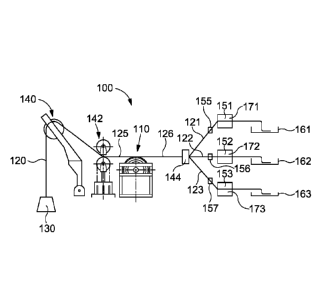
Figure 1 shows a schematic side view representation of a load-bearing
apparatus 100 according to a first embodiment of the present invention.
The exemplary load-bearing apparatus 100 of Figure 1 reflects an offshore
application such as an off-shore platform or vessel. However, the load-bearing
apparatus 100 may equally find use in other applications, for example cranes
such as
off-shore on on-land cranes; towing systems; weight, counterweight, or
cantilever
devices; tension controlling devices; structural applications such as station
keeping or
any other structural applications requiring dynamic positioning and/or
tensioning of a
structure; or the like.
The load-bearing apparatus 100 comprises a winch apparatus 110.
The load-bearing apparatus 100 also comprises a load-bearing spoolable
medium 120 for connecting to a load 130.
The load-bearing spoolable medium 120 is shown in schematic form in Figures
1 and 2 for ease of reading. The load-bearing spoolable medium 120 comprises a
plurality of load-bearing elements 121,122,123, best shown in figures 3 and 4.
In this embodiment, the plurality of load-bearing elements comprises three
load-
bearing elements 121,122,123.
A portion of the load-bearing spoolable medium 120 is spooled about the winch
apparatus 110.
The winch apparatus 110 is configured to control paying out and/or paying in
of
the load-bearing spoolable medium 120. The winch apparatus 110 is configured
to
function as a detensioning device to reduce tension within the load-bearing
spoolable
medium 120.
The load-bearing spoolable medium 120 defines an outboard or high tension
portion 125, between the load 130 and the winch apparatus 110, and defines an
inboard or low tension portion 126, on a side of the winch apparatus 110
opposite the
load 130.
The load-bearing spoolable medium 120 and the winch apparatus 110 are
described in more detail with reference to Figures 2, 3 and 4.
The load-bearing apparatus 100 includes an overboarding assembly 140 which
is used to appropriately direct a spoolable medium 120 from a vessel (not
shown) into
the sea. Additionally, a heave compensator 142 is provided which provides
dynamic
CA 02907877 2015-09-23
WO 2014/170671 PCT/GB2014/051190
24
compensation to the spoolable medium 120 to accommodate for heaving motion of
the
associated vessel.
The load-bearing apparatus 100 comprises a guide 144 for guiding each of the
load-bearing elements 121,122,123 towards a respective tension control
apparatus
151,152,153. The tension control apparatuses 151,152,153 are provided to
control,
apply and/or adjust the tension of a respective load-bearing element
121,122,123, on
an inboard portion 126 thereof.
The tension control apparatus 151,152,153 is further described in more detail
with reference to Figures 5 and 6.
The load-bearing apparatus 100 further includes a storage apparatus
161,162,163, which in this embodiment is provided in the form of a plurality
of storage
baskets 161,162,163, which permit a respective load-bearing element
121,122,123 to
be stored in a zero or near zero tension state.
Figure 2 shows a load-bearing apparatus 200 according to a second
embodiment of the present invention, showing load-bearing spoolable medium 220
and
winch apparatus 210. The load-bearing spoolable medium 220 and winch apparatus
210 are generally similar to the load-bearing spoolable medium 120 and winch
apparatus 110 of Figure 1, like part denoted by like numerals, incremented by
'100'.
The winch apparatus 210 has a contact surface 211 configured for engaging
the load-bearing spoolable medium 220. Although not shown in the schematic
representation of Figure 2 for ease of representation, load-bearing spoolable
medium
220 comprises a plurality of load-bearing elements arranged side-by-side on
contact
surface 211 of the winch apparatus 210.
In the embodiment of Figure 2, the contact surface 211 of the winch apparatus
210 comprises a plurality of circumferentially arranged support elements 212
or slats
each having discrete contact surfaces which collectively define a drum contact
surface.
Figure 3 shows a load-bearing apparatus 300 according to a third embodiment
of the present invention, showing load-bearing spoolable medium 320 and winch
apparatus 310. The load-bearing spoolable medium 320 and winch apparatus 310
are
generally similar to the load-bearing spoolable medium 120 and winch apparatus
110
of Figure 1, like part denoted by like numerals, incremented by '200'.
In the embodiment of Figure 3, the contact surface 311 of the winch apparatus
310 comprises a substantially continuous, flat, surface 313.
Figure 4 shows a load-bearing apparatus 400 according to a fourth
embodiment of the present invention, showing load-bearing spoolable medium 420
and
CA 02907877 2015-09-23
WO 2014/170671 PCT/GB2014/051190
winch apparatus 410. The load-bearing spoolable medium 420 and winch apparatus
410 are generally similar to the load-bearing spoolable medium 420 and winch
apparatus 410 of Figure 1, like part denoted by like numerals, incremented by
'300'.
In the embodiment of Figure 4, the contact surface 411 of the winch apparatus
5 410
comprises a grooved surface having groove 414. The groove 414 is arranged to
receive and guide the plurality of load-bearing elements 421,422,423 on the
contact
surface 411 as the load-bearing elements 421,422,423 are wound about the winch
apparatus 410.
In the embodiments of Figures 3 and 4, the load-bearing spoolable medium
10 320,420
comprises three separate, distinct load-bearing elements 321,322,323 and
421,422,423 arranged side-by-side. Provision of a plurality of load-bearing
elements
121,122,123, 321,322,323 and 421,422,423 arranged side-by-side permits
reduction of
a diameter of each of the load-bearing elements 121,122,123, 321,322,323 and
421,422,423 compared to a diameter of a corresponding single load-bearing
medium
15 that
would be required to support the same load 130. One of the effects and
advantages of such reduction in diameter of the load-bearing elements
121,122,123,
321,322,323 and 421,422,423 is that the diameter of the winch apparatus
110,310,410
used with such load-bearing elements 121,122,123, 321,322,323 and 421,422,423
may be reduced, therefore reducing costs, ease of handling, and safety.
20 In this
embodiment, each load-bearing element 321,322,323 and 421,422,423
comprises a synthetic fibre rope. The provision of three load-bearing elements
significantly reduces the diameter appropriate for the winch apparatus
310,410, while
maintaining the number of load-bearing elements relatively low to minimise
difficulty of
handling or risks of malfunction associated with a multiple rope system.
25 For a
load of 250Te, a standard 136mm diameter single rope having a minimum
break load (MBL) of 1125Te would give a safety factor of 4.5.
For the same load capacity, each of the three load-bearing elements
321,322,323 and 421,422,423 of Figures 3 and 4 may have a diameter in the
region of
70-90 mm, e.g. approximately 78 mm. This reduced diameter in each of the load-
bearing elements allows reduction in he diameter of the associated winch
apparatus
310,410.
In other embodiments using two load-bearing elements (not shown), each of the
two load-bearing elements may have a diameter in the region of 80-100 mm, e.g.
approximately 88 mm. This reduced diameter in each of the load-bearing
elements
allows reduction in he diameter of the associated winch apparatus 310,410.
CA 02907877 2015-09-23
WO 2014/170671 PCT/GB2014/051190
26
In other embodiments using four load-bearing elements (not shown), each of
the four load-bearing elements may have a diameter in the region of 50-80 mm,
e.g.
approximately 66 mm. This reduced diameter in each of the load-bearing
elements
allows reduction in he diameter of the associated winch apparatus 310,410.
Figures 3 and 4 depict load-bearing elements 321,322,323 and 421,422,423
having a substantially circular cross-section.
However, this is for ease of
representation only, and other rope profiles may be equally suitable for use
in the
present invention, such as flat ropes, or the likes.
The load-bearing elements 321,322,323 and 421,422,423 are substantially
parallel to each other on the contact surface 311,411 of the winch apparatus
310,410,
in a plane substantially parallel to an axis of rotation 315,415 of the winch
apparatus
310,410, and tangential to the contact surface 311,411.
In this embodiment, the load-bearing spoolable medium 320,420 defines three
turns around the winch apparatus 310,410. It will be understood that the load-
bearing
spoolable medium 320,420 may define fewer, or more, turns, but only three
turns are
shown in Figures 3 and 4 for ease of understanding.
The load-bearing elements 321,322,323 and 421,422,423 are provided in
sequential order around the contact surface 311,411 of the winch apparatus
310,410.
That is, each of the first, second and third turns (represented respectively
by suffix
a,b,c) defines in sequential order first, second and third load-bearing
elements
321,322,323 and 421,422,423. A turn of a load-bearing element may be separated
from an adjacent turn of the same load-bearing element, by the remaining load-
bearing
elements. As see on Figures 3 and 4, first load-bearing element 321a,421a of
the first
turn is separated from first load-bearing element 321b,421b of the second turn
by
second and third load-bearing elements 322a,323a,422a,423a of the first turn.
Similarly, first load-bearing element 321b,421b of the second turn is
separated from
first load-bearing element 321c,421c of the third turn by second and third
load-bearing
elements 322b,323b,422b,423b of the second turn.
In this embodiment, the diameter of each of the plurality of load-bearing
elements 321,322,323 and 421,422,423 is identical.
Figure 5 is a side view of a tension control apparatus 551 according to a
fifth
embodiment of the present invention. The tension control apparatus 551 is
generally
similar to the tension control apparatus 151,152,153 of Figure 1, like part
denoted by
like numerals, incremented by '400'.
27
In the embodiment of Figure 5, the tension control apparatus 551 comprises a
tension control device 552 for engaging load-bearing element 521. The tension
control
device 552 is in the form of a track tensioner.
Figure 6 is a side view of a tension control apparatus 651 according to a
sixth
embodiment of the present invention. The tension control apparatus 651 is
generally similar
to the tension control apparatus 151,152,153 of Figure 1, like part denoted by
like numerals,
incremented by '500'.
In the embodiment of Figure 6, the tension control apparatus 651 comprises a
tension control device 652 for engaging load-bearing element 621. The tension
control
device 652 is in the form of a drum, winch or sheave.
Referring back to Figure 1, each tension control apparatus 151,152,153 is
provided
to control, apply and/or adjust the tension of a respective load-bearing
element
121,122,123, on an inboard portion 126 thereof.
In this embodiment, the tension control apparatus 151,152,153 are arranged to
maintain a difference in tension between the load-bearing elements 121,122,123
at a
predetermined level, e.g. below an upper limit such as below about 20%, e.g.
below about
10%, e.g. below about 5%. In another embodiment, the tension control apparatus
151,152,153 are configured to maintain or apply different tensions between the
load-bearing
elements. This may help accommodate, for example, operational or environmental
requirements, fatigue or wear of one or more load-bearing elements, etc.
In this embodiment, each tension control apparatus 151,152,153 comprises a
respective sensing device 155,156,157 which is arranged to measure the tension
of a
respective load-bearing element 121,122,123 on an inboard portion 126 thereof.
In this embodiment, each tension control apparatus 151,152,153 comprises a
respective actuator 171,172,173, which in this embodiment forms part of a
respective
tension control device 151,152,153, and comprises a motor.
By such provision, the tension of each load-bearing element 121,122,123 may be
individually and independently controlled, which may allow the apparatus 100
and/or a user
to apply a desired tension on a outboard portion 125 of each load-bearing
element
121,122,123.
It should be understood that the embodiments described herein are merely
exemplary and that various modifications may be made thereto without departing
from the
scope of the present invention.
Date Recue/Date Received 2020-05-06