Note: Descriptions are shown in the official language in which they were submitted.
CA 02908209 2015-09-28
WO 2014/155367 PCT/1B2014/060295
1
Prevention of inadvertent battery depletion Ii an automatic external
defibrillator
FIELD OF THE INVENTION
This invention relates to battery powered medical devices used in cardiac
resuscitation rescues and, in particular, to defibrillators.
BACKGROUND OF THE INVENTION
Cardiac arrest is a life-threatening medical condition in which the patient's
heart fails to provide blood flow to support life. A defibrillator can be used
to deliver
defibrillating shocks to a patient suffering from cardiac arrest. The
defibrillator resolves this
condition by delivering a high-voltage impulse to the heart in order to
restore normal rhythm
and contractile function in patients who are experiencing arrhythmia such as
VF (ventricular
fibrillation) or VT (ventricular tachycardia) that is not accompanied by
spontaneous
circulation. One type of defibrillator, the automated external defibrillator
(AED), differs
from manual defibrillators in that the AED can automatically analyze the
electrocardiogram
(ECG) rhythm to determine if defibrillation is necessary. The defibrillator
analyzes the ECG
signal for signs of arrhythmia. If VF is detected, the defibrillator signals
the rescuer that a
shock is advised. After the detection of VF or other shockable rhythm, the
rescuer presses a
shock button on the defibrillator to deliver a defibrillation pulse to
resuscitate the patient.
Defibrillation must be delivered very soon after the onset of cardiac arrest
in
order to be effective. It is estimated that the chance of survival falls by
10% for every minute
of delay to defibrillation beyond four minutes after cardiac arrest. Hence,
AEDs are designed
to be used by first responders, such as firefighters, police, or lay
bystanders, who are the most
likely to arrive at the patient's side first. Once an AED is brought to the
patient, the rescuer
must deploy and use it quickly.
Some prior art defibrillators are designed to power on automatically when the
defibrillator carry case is opened in order to minimize the time until the AED
is ready to
delivery therapy. For example, U.S. Patent 6,083,246, entitled "Lid open
detection circuit for
automated external defibrillators" by Stendahl et al. describes an AED which
automatically
activates when a lid is opened to deploy the electrodes inside. Another co-
assigned
application, PCT/M2011/054822 entitled "CARRYING CASE WITH IMPROVED
CA 02908209 2015-09-28
WO 2014/155367 PCT/1B2014/060295
2
ACCESS FOR DEFIBRILLATOR AND ACCESSORIES" by Roach et al. and herein
incorporated by reference, describes a defibrillator system in which a
carrying case has a lid
open sensor for automatically activating the defibrillator inside when the
case is opened.
AEDs often include electrodes and other accessories which aid in the
administration of cardiopulmonary resuscitation (CPR) during the rescue.
Figure 1 illustrates
one defibrillator carrying case, in which a set of patient electrodes 140 and
a fast response kit
130 are stored within the case with the AED itself.
Such prior art defibrillators are portable and battery powered. Each time that
the defibrillator is automatically activated by opening the lid, the battery
suffers some
depletion. It is important then that the automatic activation is intended for
some purpose.
Otherwise, the defibrillator battery is unnecessarily depleted, which costs
money and
potentially delays therapy while the depleted battery is changed out.
Inadvertent activation of the defibrillator can occur for a variety of
reasons.
The carry case latch may fail in a way that is not readily observable by the
owner. The
automatic power on sensor may malfunction and issue spurious activation
indications to the
device. More commonly, the carry case becomes overstuffed with accessories,
which causes
the case to become distorted such that the case opening sensor activates. Any
of these
problems would cause the automatic power on feature to unnecessarily activate
the
defibrillator and deplete the battery. What is needed then is a solution to
this problem.
SUMMARY OF THE INVENTION
In accordance with the objectives of the present invention, an improved
automatic power on feature for a defibrillator is described which detects
likely circumstances
of inadvertent activation. The invention generally encompasses the detecting
that there is a
pattern of the defibrillator powering on automatically and not being used for
therapy or
diagnostic evaluation, e.g. a typical intended use. When the defibrillator
detects such a
pattern of events, the automatic power on feature is disabled. Then, when the
AED is used in
a manner that indicates the AED has been handled by a human such as replacing
the battery
or powering on the AED manually via the on/off switch, the automatic power on
feature is
re-enabled.
The invention is disposed such that a routine maintenance event such as
opening the case on a regular basis (such as once per shift) to verify
contents/expiration dates
of items in the carry case will not cause the automatic power on feature to be
disabled.
CA 02908209 2015-09-28
WO 2014/155367 PCT/1B2014/060295
3
In accordance with the objectives of the invention, a portable defibrillator
apparatus is described comprising an electrode connector, an operator actuated
button, an
automatic power on circuit which is operable to actuate the defibrillator
independent of the
operator actuated button, and a controller in electrical communication with
the electrode
connector, the operator actuated button and the automatic power on circuit.
The controller is
operable to detect a pattern of events and is further operable to disable the
automatic power
on circuit in response to the detected pattern of events.
In accordance with yet another aspect of the invention, a method for managing
a power condition of a defibrillator is described, comprising a first step of
providing a
defibrillator in a low power standby condition, the defibrillator including a
controller in
electrical communication with an electrode connector, an operator actuated
button, and an
automatic power on circuit operable to actuate the defibrillator independent
of the operator
actuated button. The method also includes the steps of automatically
activating the
defibrillator with the automatic power on circuit, detecting a pattern of
events based on the
automatically activating step, disabling the automatic power on circuit based
on the detecting
step, and returning the defibrillator to the low power standby condition with
the automatic
power on circuit disabled. The method also includes optionally re-enabling the
automatic
power on circuit by means of a subsequent user action.
BRIEF DESCRIPTION OF THE DRAWINGS
FIGURE lillustrates a defibrillator apparatus including a carrying case and a
case opening sensor, the carrying case in the open position.
FIGURE 2 illustrates a functional circuit diagram according to one
embodiment of the invention.
FIGURE 3 is a flow chart illustrating one embodiment of the inventive
method.
DETAILED DESCRIPTION OF THE EMBODIMENTS
Referring first to FIGURE 1, a defibrillator apparatus 100 according to the
principles of the present invention is shown in the open position. A carrying
case 105 having
a lid 107 is sized to contain and protect components needed for a cardiac
arrest rescue, such
as an AED with pre-connected electrodes 140, a CPR meter, and a fast response
kit 130. The
electrodes are connected to the defibrillator at electrode connector 110 prior
to use, in order
CA 02908209 2015-09-28
WO 2014/155367 PCT/1B2014/060295
4
to reduce the steps needed for deployment and optionally to allow the
electrode condition to
be periodically tested during storage.
Case 105 preferably comprises a case opening sensor 150. Lid 107 preferably
comprises a case open indicator disposed adjacent to sensor 150 when the lid
is closed. The
case open indicator is preferably a magnet 160, but may also comprise a
mechanical button or
plunger. Defibrillator 100 thus senses an open lid by the absence of magnet
160 next to
sensor 150, and in response automatically turns itself on. It is noted that a
corresponding
feature that automatically turns portable defibrillator 100 off upon the
shutting of lid 107 is
preferably avoided, in order to prevent unnecessary delay and confusion
involved with an
inadvertent lid closure, and unintended defibrillator shutdown, during rescue.
The defibrillator shown in FIGURE 1 is preferably disposed to automatically
shut itself off and return to a standby state after sensing a long period of
time with no
activity. No sensed activity may include not sensing a successful deployment
of the patient
electrodes or not sensing the press of a button. This period of inactivity is
called a timeout
period, and is preferably on the order of five minutes. Of course, the
defibrillator can also be
manually shut off by pressing an operator actuated button 120, such as an
on/off button 120
or by removing the battery, not shown. The nature of the power down event is
recorded in
defibrillator memory 218 in a pattern of events file 230, shown in FIGURE 2.
FIGURE 1 also shows the disposition of a light pipe 174 over ready status
indicator light 172. When lid 107 is shut, light pipe 174 overlays ready
status light 172. Any
indicator light signal on ready status light 172 is then transmitted through
light pipe 174 to
the exterior of portable defibrillator 100 for ease of viewing without having
to open the case.
Referring now to FIGURE 2, a functional circuit diagram is illustrated to show
the function of the inventive defibrillator. Where, equivalent, the FIGURE 2
elements
correspond in general to the physical components shown in FIGURE 1. For
example, a pair
of electrodes 240 corresponds to the FIGURE 1 electrodes 140, etc.
FIGURE 2 illustrates a controller 206 which is in electrical communication
with each of an electrode connector 242, an operator actuated button 120, and
an automatic
power on circuit 210. Controller 206 is also in communication with a memory
218 on which
is stored a data file 230 containing a pattern of events. Controller 206 is
also in
communication with a user-perceptible output, which may be an indicator light
270 or a
beeper 274. Intervening between controller 206 and electrode connector 242 is
an electrode
front end 202 which senses a deployment of a set of patient electrodes
attached to connector
CA 02908209 2015-09-28
WO 2014/155367 PCT/1B2014/060295
242, and an electrode high voltage circuit for delivering the defibrillation
therapy to the
patient via the electrodes.
FIGURE 2 also illustrates the automatic power on circuit 210 having a case
opening sensor 250, such as a Hall effect sensor, disposed adjacent a magnet
260 or
5 equivalent. Circuit 210 functions to cause controller 206 to activate the
defibrillator 200
when the case is opened.
In operation, the automatic power on circuit senses a case opening, and sends
an activation signal to controller 206. Controller 206 in turn retrieves data
of previous
activation events from memory 230. If the previous events combined with the
present
activation indicate that the activation is the latest in a pattern of events
that indicates a
repeated inadvertent activation, then controller 206 disables the automatic
power on circuit
and returns the defibrillator to a standby condition. Return to standby may
occur after the
timeout period has passed.
In a preferred embodiment, the pattern of events is comprised of a series of
detected automatic power on activations followed only by a timeout period
deactivation, with
no intervening activity. The current activation is preferably included in the
series.
Each activation/ deactivation may also be required to meet the following
criteria:
1. The defibrillator installed battery type is a use battery. This criteria
forestalls effects during training, demonstration, or administrative modes of
operation;
2. The defibrillator activation must be due to a case latch magnet;
3. The confirmed patient use is detected; and
4. The defibrillator deactivation to standby is with no or poor electrode pads
contact or with no intervening On/Off button press or with no Off softkey
press during
shutdown.
The last criterion allows for continued automatic power on functionality in
environments where the defibrillator case is periodically opened to check its
contents and/or
expiration dates. If a button is not pressed prior to closing the case again,
audible and visible
prompting normally continues, which alerts the checker to reopen the case and
to press the
"off ' button.
Optionally, controller 206 may compare a threshold periodicity criterion
against a calculated periodicity of the series data. For example, if each of
the activations
occurs at about the same time of day, or multiple times of day, the
periodicity indicates that
CA 02908209 2015-09-28
WO 2014/155367 PCT/1B2014/060295
6
the case openings are intentional shift check events. Controller 206 will not
consider such a
series as a pattern of events for purposes of disabling the automatic power on
feature.
Preferably, a series which constitutes a pattern of events comprises five
consecutive above-described activations/deactivations. When controller 206
senses the
pattern of events, it records a disable event in the memory 230 and disables
the defibrillator
power on circuit.
In an alternate embodiment, the pattern of events occurs and is detected by
controller 206 over a short period of time. Such a pattern of events may be
induced, for
example, by a faulty case opening sensor or automatic power on circuit that is
spuriously
activating. This pattern of events may be sensed as an automatic power on
activation of the
defibrillator into a use mode, followed by one or more additional automatic
power on
activations during the same use mode period. The activations would occur
without any other
detected intervening use activity. In this embodiment, controller 206 disables
the automatic
power on circuit 210 shortly after the last event in the pattern occurs, such
as after a set
number of sensed automatic power on activations, without waiting for the end
of the timeout
period.
When the circuit 210 is disabled, any subsequent opening of the defibrillator
case leaves the defibrillator in standby until it is manually activated by a
user action. Such
user action includes pressing the on/off button 120, pressing a shock button
120', or
deploying the patient electrodes 240. When controller 206 senses the user
action, the
defibrillator is activated for use with no further delay.
Optionally, a user indication at user perceptible output 270 may be issued by
controller 206 during the periods when the automatic power on circuit 210 is
disabled. The
indication may be a flashing light at indicator light 272 or an aural alert
when the case is
opened at beeper 274.
Controller 206 may subsequently re-enable the automatic power on circuit 210
when the defibrillator is manually activated. Thus, a sensed press of the
operator actuated
button, or a sensed deployment of the electrodes at electrode connector 242
may reset the
pattern of events file in memory, and the series detection will begin again.
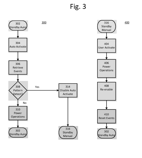
FIGURE 3 illustrates a method 300 for managing a power condition of a
defibrillator corresponding to the above-described defibrillator
functionality. The method 300
begins at step 302 wherein the defibrillator is in a standby mode of operation
with an
automatic power on feature enabled. At step 304, the automatic power on
feature activates
the defibrillator, responding to a sensed opening of the case lid or an
equivalent sensing. Data
CA 02908209 2015-09-28
WO 2014/155367 PCT/1B2014/060295
7
regarding previous activations of the defibrillator is retrieved from memory
at step 306. The
data combined with the circumstances of the current activation are analyzed at
step 308 to
detect a pattern of events as previously described. If such a pattern of
events is detected at
step 308, then the automatic power on feature is disabled at 314. The
defibrillator then
returns to a standby mode of operation at step 316, either immediately or
after a timeout
period. The defibrillator at step 316 is in a standby state with the automatic
power on circuit
disabled. Subsequent activations must occur by a manual user action. Such user
action
includes one of installing a battery, pressing a button, or deploying
electrodes.
The automatic power on feature can be re-enabled by means of the re-enabling
method 400 as shown in FIGURE 3. The defibrillator is in the standby state at
step 316, upon
which a user manually activates the defibrillator at step 404 by the manual
action. The
defibrillator operates in a use state, e.g. for defibrillation, at step 406 as
intended by the user.
At step 408, the controller re-enables the automatic power on feature, and
optionally resets
the series of activation events in memory at step 410. When the use is
complete, the
defibrillator is again placed into the standby state at step 302, having the
automatic power on
feature activated.
Several variations within the scope of the afore-described invention will
readily occur to those skilled in the art. For instance, the defibrillator may
include an
administrative option to modify the pattern of events which would cause the
disabling step to
conform to a local practice. The feature could be selectable altogether by an
administrator as
well. In addition, the precise mode of sensing an automatic activation may
vary, such as by
means of a latch pull, sensing of a case motion, etc. Other parameters of the
pattern of events
criteria, such as the threshold number of activations without intervening
activity, could also
be modified to adjust the sensitivity and specificity of the disabling feature
as desired by the
user.