Note: Descriptions are shown in the official language in which they were submitted.
CA 02908231 2015-10-09
,
,
RESIDUAL WATER SCAVENGING PROCESSING METHOD IN FUEL
CELL SYSTEM AND FUEL CELL SYSTEM
CROSS-REFERENCE TO RELATED APPLICATIONS
[0001]
This application claims priority based on Japanese Patent
Application No. 2014-227017 filed on November 7, 2014.
BACKGROUND
FIELD
[0002]
The present invention relates to residual water scavenging
processing in a fuel cell system.
RELATED ART
[0003]
When the outside temperature is lowered below freezing point after
the stop of an operation of a fuel cell system, in the interior of a unit cell
forming a fuel cell (cell stack), a reaction gas flow path formed within the
fuel
cell, an external piping and the like, water may be frozen. When water is
frozen in the fine pores of a catalyst layer and a gas diffusion layer within
a
unit cell, at the time of the subsequent startup of the fuel cell system, the
gas
diffusion property is lowered to reduce the power generation performance.
When in a valve provided in the reaction gas flow path, water is frozen, the
opening and closing of the valve is inhibited, and the distribution of a
reaction gas and an off-gas is inhibited. Hence, a method has been proposed
in which after the stop of a fuel cell system, the temperature of a fuel cell
and
the outside temperature are measured, and when these temperatures
become equal to or less than a predetermined temperature, residual water
scavenging processing is performed to discharge water within the fuel cell
system. JP2010-198786A discloses a method in which when the ignition of
a vehicle mounting the fuel cell system is off, and the temperature of a fuel
cell is equal to or less than a predetermined temperature, residual water
scavenging is performed on a fuel gas supply/discharge mechanism and an
oxidizer gas supply/discharge mechanism. JP2008-218242A discloses a
method in which when the outside temperature is measured during the stop
1
CA 02908231 2015-10-09
of an operation of a fuel cell, and the outside temperature is equal or less
than a predetermined temperature, residual water scavenging is performed
on a fuel gas supply/discharge mechanism and an oxidizer gas
supply/discharge mechanism.
[0004]
It is assumed that in order to more reliably prevent water from being
frozen within a fuel cell system, the two methods described above are
combined, residual water scavenging processing is performed according to
the temperature of a fuel cell when an ignition is off and the residual water
scavenging processing is performed according to the outside temperature
during the stop of the fuel cell system. However, in such a configuration,
since the residual water scavenging processing is performed a large number
of times, power consumption in devices performing the residual water
scavenging processing such as an air compressor and the injector of
hydrogen gas is disadvantageously increased. Moreover, in a case where
the residual water scavenging processing is performed when an ignition is off,
even though the ignition is off, vibrations and sound caused by the operation
of the air compressor and the like are produced until the completion of the
residual water scavenging processing, and thus an uncomfortable feeling is
disadvantageously given to a user. Hence, a technology is desired in which
it is possible to suppress the freezing of water within a fuel cell system
while
reducing power consumption necessary for residual water scavenging
processing and the giving of an uncomfortable feeling to the use.
SUMMARY
[0005]
The present invention is made to solve at least part of the foregoing
problem, and can be realized as aspects below.
[0000
(1) According to one aspect of the present invention, there is provided
a residual water scavenging processing method in a fuel cell system
including a fuel gas supply/discharge mechanism and an oxidizer gas
supply/discharge mechanism. The residual water scavenging processing
method includes: a first prediction step of predicting, while the fuel cell
system is operated, whether or not an outside temperature of the fuel cell
system becomes equal to or less than a first predetermined temperature; a
2
CA 02908231 2015-10-09
step of performing, when in the first prediction step, it is predicted that
the
outside temperature becomes equal to or less than the first predetermined
temperature, residual water scavenging processing on only the oxidizer gas
supply/discharge mechanism among the fuel gas supply/discharge
mechanism and the oxidizer gas supply/discharge mechanism and thereafter
stopping the operation of the fuel cell system; a second prediction step of
predicting, after stop of the operation of the fuel cell system, whether or
not a
temperature of a predetermined component included in the fuel cell system
becomes equal to or less than a second predetermined temperature; and a
step of performing the residual water scavenging processing on the fuel gas
supply/discharge mechanism when in the second prediction step, it is
predicted that the temperature of the predetermined component becomes
equal to or less than the second predetermined temperature.
In the residual water scavenging processing method of this aspect,
since before the stop of the operation of the fuel cell system, the residual
water scavenging processing is performed on only the oxidizer gas
supply/discharge mechanism among the fuel gas supply/discharge
mechanism and the oxidizer gas supply/discharge mechanism but the
residual water scavenging processing is not performed on the fuel gas
supply/discharge mechanism, as compared with the configuration in which
the residual water scavenging processing is also performed on the fuel gas
supply/discharge mechanism, it is possible to reduce power consumption for
the residual water scavenging processing. Since it is possible to reduce the
processing time, it is possible to reduce an uncomfortable feeling given to a
user. Since before the stop of the operation of the fuel cell system, the
residual water scavenging processing is performed on the oxidizer gas
supply/discharge mechanism, as compared with the configuration in which
the residual water scavenging processing is performed after the stop of the
operation, it is possible to perform the scavenging on the oxidizer gas
supply/discharge mechanism under an environment of a higher temperature.
Hence, it is possible to discharge water within the cathode of the fuel cell
as
water vapor, and thus it is possible to more reliably discharge the water
within the cathode. When it is predicted that after the stop of the operation
of the fuel cell system, the temperature of the predetermined component
becomes equal to or less than the second predetermined value, since the
residual water scavenging processing is performed on the fuel gas
3
CA 2908231 2017-04-03
supply/discharge mechanism, as compared with conditions before the stop of
the operation, it is possible to perform the scavenging on the fuel gas
supply/discharge mechanism under an environment of a lower temperature.
Hence, the scavenging can be performed in a state where a larger amount of
water vapor within the atmosphere of the fuel gas supply/discharge
mechanism is condensed, and thus it is possible to discharge a larger amount
of water.
[0007]
(2) The residual water scavenging processing method of the above
aspect may further include a step of storing, in a storage device included in
the fuel cell system, whether or not the residual water scavenging processing
has been performed on the oxidizer gas supply/discharge mechanism, and
the step of performing the residual water scavenging processing on the fuel
gas supply/discharge mechanism may include: a step of performing the
residual water scavenging processing on the fuel gas supply/discharge
mechanism but failing to perform the residual water scavenging processing
on the oxidizer gas supply/discharge mechanism when in the second
prediction step, it is predicted that the temperature of the predetermined
component becomes equal to or less than the second predetermined
temperature and when before the stop of the operation of the fuel cell system,
the residual water scavenging processing is performed on the oxidizer gas
supply/discharge mechanism; and a step of performing the residual water
scavenging processing on the fuel gas supply/discharge mechanism and the
oxidizer gas supply/discharge mechanism when in the second prediction step,
it is predicted that the temperature of the predetermined component
becomes equal to or less than the second predetermined temperature and
when before the stop of the operation of the fuel cell system, the residual
water scavenging processing is not performed on the oxidizer gas
supply/discharge mechanism. In the scavenging method of this aspect,
when before the stop of the operation of the fuel cell system, the residual
water scavenging processing is performed on the oxidizer gas
supply/discharge mechanism, even if it is predicted that the temperature of
the predetermined component becomes equal to or less than the second
predetermined temperature, the residual water scavenging processing is not
performed. Hence, even when before the stop of the operation of the fuel
cell system, the residual water scavenging processing is performed on the
4
CA 02908231 2015-10-09
,
,
oxidizer gas supply/discharge mechanism, and it is predicted that the
temperature of the predetermined component becomes equal to or less than
the second predetermined temperature, as compared with the configuration
in which the residual water scavenging processing is performed on the
oxidizer gas supply/discharge mechanism, it is possible to reduce the power
consumption necessary for the residual water scavenging processing.
Moreover, it is possible to reduce the degradation of the fuel cell caused by
the residual water scavenging processing on the oxidizer gas
supply/discharge mechanism after the stop of the operation.
[00081
(3) In the residual water scavenging processing method of the above
aspect, the first predetermined temperature may be equal to or less than 0
degrees Celsius. In the residual water scavenging processing method of this
aspect, since the first predetermined temperature is equal to or less than 0
degrees Celsius, when it is highly likely that the temperature of the fuel
cell
system becomes equal to or less than 0 degrees Celsius, and it is highly
likely
that in the fuel cell system, water is frozen, it is possible to perform the
residual water scavenging processing on the oxidizer gas supply/discharge
mechanism. Hence, in the fuel cell system, the residual water scavenging
processing under temperature conditions (for example, conditions in which
the temperature is higher than 0 degrees Celsius) in which water is not
frozen can be reduced, and thus it is possible to reduce the power
consumption.
[00091
(4) In the residual water scavenging processing method of the above
aspect, the second predetermined temperature may be 0 degrees Celsius.
In the residual water scavenging processing method of this aspect, when the
temperature of the predetermined component included in the fuel cell system
is equal to or less than 0 degrees Celsius, that is, when it is very highly
likely
that the temperature of the fuel cell system is equal to or less than 0
degrees
Celsius, it is possible to perform the residual water scavenging processing on
the fuel gas supply/discharge mechanism. Hence, it is possible to more
reliably reduce the residual water scavenging processing under temperature
conditions in which water is not frozen in the fuel cell system.
[0010]
(5) In the residual water scavenging processing method of the above
CA 02908231 2015-10-09
aspect, the predetermined component may be at least one of a valve provided
so as to discharge water in the fuel gas supply/discharge mechanism and a
valve provided so as to discharge water in the oxidizer gas supply/discharge
mechanism. Since the valve provided so as to discharge water in the fuel
gas supply/discharge mechanism and the valve provided so as to discharge
water in the oxidizer gas supply/discharge mechanism discharge water by
utilizing gravity, in general, the valves are arranged in a position which is
vertically downward of the fuel cell system and which is closer to the
outside.
Hence, these valves are more likely to be affected by the outside temperature,
and the temperature thereof is most easily lowered under a low temperature
environment. Therefore, when the temperature of at least one of these
valves is equal to or less than the second predetermined temperature, the
residual water scavenging processing is performed, and thus it is possible to
perform the residual water scavenging processing before the temperature of
the individual constituent elements of the fuel cell system becomes equal to
or less than the second predetermined temperature.
[0011]
The present invention can also be realized in various aspects. For
example, the present invention can be realized in the fuel cell system, a fuel
cell automobile on which the fuel cell system is mounted, a program for
realizing the residual water scavenging processing in the fuel cell system, a
recoding medium in which such program is recorded, and the like.
BRIEF DESCRIPTION OF DRAWINGS
[0012]
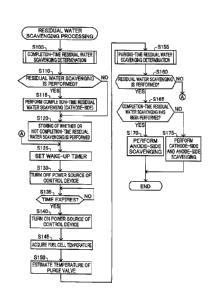
Fig. 1 is a block diagram showing a schematic configuration of a fuel
cell system to which a residual water scavenging processing method
according to an embodiment of the present invention is applied:
Fig. 2 is a flowchart showing the procedure of residual water
scavenging processing performed in the fuel cell system;
Fig. 3A is a flowchart showing the procedure of completion-time
residual water scavenging determination processing in the present
embodiment;
Fig. 3B is a flowchart showing the detailed procedure of processing in
step S200 shown in Fig. 3A; and
Fig. 4 is a flowchart showing the procedure of parking-time residual
6
CA 02908231 2015-10-09
water scavenging determination processing in the present embodiment.
DESCRIPTION OF EMBODIMENTS
[0013]
A. Embodiment
Al. System configuration:
Fig. 1 is a block diagram showing a schematic configuration of a fuel
cell system to which a residual water scavenging processing method
according to an embodiment of the present invention is applied. The fuel
cell system 10 of the present embodiment is used to be mounted on a fuel cell
automobile as a system for supplying power for driving. The fuel cell
system 10 includes a fuel cell 100, a fuel gas supply/discharge mechanism
200 also called a fuel gas supply/discharge system, an oxidizer gas
supply/discharge mechanism 300 also called an oxidizer gas
supply/discharge system, a fuel cell circulation cooling mechanism 400 also
called a fuel cell circulation cooling system, a power charging/discharging
mechanism 500 also called a power charging/discharging system, a control
device 600 and a startup control device 700.
[0014]
The fuel cell 100 is a so-called solid polymer-type fuel cell, and
includes a cell stack formed with a plurality of unit cells 110 stacked in
layers along a stacking direction SD, and a pair of current collector plates
111 that are arranged at both ends of the cell stack to function as an overall
electrode. Each unit cell 110 generates power by the electrochemical
reaction of hydrogen serving as a fuel gas supplied to an anode-side catalyst
electrode layer provided to sandwich a solid polymer electrolyte membrane
and oxygen included in air serving as an oxidizer gas supplied to a
cathode-side catalyst electrode layer. The catalyst electrode layer contains
carbon particles carrying a catalyst, for example, platinum (Pt) and an
electrolyte. On the outsides of the catalyst electrode layers at both
electrode sides of the unit cells 110, gas diffusion layers formed with a
porous
member are arranged. As the porous member, for example, a carbon porous
member such as carbon paper or carbon cloth or a metal porous member such
as a metal mesh or a foam metal is used. Within the fuel cell 100, manifolds
(not shown) for distributing the fuel gas, the oxidizer gas and a cooling
medium are formed along the stacking direction SD.
7
CA 02908231 2015-10-09
[0015]
The fuel gas supply/discharge mechanism 200 supplies the fuel gas to
the fuel cell 100 and discharges an anode-side off-gas from the fuel cell 100.
The fuel gas supply/discharge mechanism 200 includes a hydrogen tank 210,
an interruption valve 220, an injector 221, a gas-liquid separator 250, a
circulation pump 240, a purge valve 260, a fuel gas supply path 231, a first
fuel gas discharge path 232, a fuel gas circulation path 233 and a second fuel
gas discharge path 262.
[0016]
The hydrogen tank 210 stores high-pressure hydrogen, and supplies
hydrogen gas serving as the fuel gas through the fuel gas supply path 231 to
the fuel cell 100. The interruption valve 220 is arranged in the vicinity of
the supply port of the fuel gas in the hydrogen tank 210, and switches the
supply and stop of the hydrogen gas from the hydrogen tank 210. The
injector 221 is arranged in the fuel gas supply path 231, and adjusts the
supplied amount and the pressure of the hydrogen gas to the fuel cell 100.
The gas-liquid separator 250 is arranged in the first fuel gas discharge path
232, separates water contained in the anode-side off-gas discharged from the
fuel cell 100 to discharge it to the second fuel gas discharge path 262 and
discharges, to the fuel gas circulation path 233, the fuel gas which is a gas
obtained by separating the water. The circulation pump 240 is arranged in
the fuel gas circulation path 233, and supplies the fuel gas discharged from
the gas-liquid separator 250 to the fuel gas supply path 231. The purge
valve 260 is arranged in the second fuel gas discharge path 262, and opens
the valve to allow the water separated by the gas-liquid separator 250 to be
discharged into the atmosphere. In the present embodiment, the opening
and closing of the purge valve 260 is performed at predetermined intervals
while the fuel cell system 10 is normally operated. The purge valve 260 is
kept opened while residual water scavenging processing which will be
described later is performed. The gas-liquid separator 250 communicates
with the fuel cell 100 through the first fuel gas discharge path 232, and when
the purge valve 260 is opened, the purge valve 260 communicates with the
atmosphere through the second fuel gas discharge path 262. Since the
pressure within the fuel cell 100 is higher than the atmosphere, when the
purge valve 260 is opened, the water stored within the gas-liquid separator
250 is discharged to the second fuel gas discharge path 262 by the pressure
8
CA 02908231 2015-10-09
difference between the fuel cell 100 and the atmosphere. The processing in
which as described above, the purge valve 260 is opened to release the
pressure within the gas-liquid separator 250 and thereby discharges the
water stored within the gas-liquid separator 250 is referred to as "normal
water discharge processing" in the following description. In the normal
water discharge processing, since an air compressor 320, the circulation
pump 240 and the like are not driven, as compared with the residual water
scavenging processing which will be described later, power consumption,
that is, consumption energy is very small.
[0017]
In the present embodiment, the purge valve 260 described above is
arranged most vertically downward among the individual constituent
elements of the fuel cell system 10 other than the second fuel gas discharge
path 262 and an oxidizer gas discharge path 332. This is because of the
following reasons. Specifically, in order to collect, with the gas-liquid
separator 250, a larger amount of water present on the anode side of the fuel
cell 100, the gas-liquid separator 250 is arranged on the vertically downward
side in the fuel cell system 10, and furthermore, in order to rapidly
discharge
the water stored in the gas-liquid separator 250 by utilizing gravity, the
purge valve 260 is arranged vertically downward of the gas-liquid separator
250; in order to satisfy these requirements, the purge valve 260 is arranged
most vertically downward among the constituent elements other than the
second fuel gas discharge path 262 and the oxidizer gas discharge path 332.
As described above, in the fuel cell system 10, the purge valve 260 is
arranged in a relatively vertically downward position, and is affected by the
outside temperature as compared with the constituent elements other than
the second fuel gas discharge path 262 and the oxidizer gas discharge path
332.
[0018]
The oxidizer gas supply/discharge mechanism 300 supplies the
oxidizer gas to the fuel cell 100 and discharges a cathode-side off-gas from
the fuel cell 100. The oxidizer gas supply/discharge mechanism 300
includes an air cleaner 310, the air compressor 320, a back pressure valve
340, an oxidizer gas supply path 331 and an oxidizer gas discharge path 332.
The air cleaner 310 removes foreign substances such as dust in the air with a
filter provided therewithin, and supplies the air after the removal of the
9
CA 02908231 2015-10-09
,
foreign substances to the air compressor 320. The air compressor 320
compresses the air supplied from the air cleaner 310 and feeds out it to the
oxidizer gas supply path 331. The back pressure valve 340 is arranged in
the oxidizer gas discharge path 332, and adjusts a so-called back pressure
that is a pressure on the cathode discharge side in the fuel cell 100. The
oxidizer gas discharge path 332 is connected to the second fuel gas discharge
path 262 described above, and the water and the cathode-side off-gas
discharged through the oxidizer gas discharge path 332 are discharged into
the atmosphere together with the water and the anode-side off-gas
discharged through the second fuel gas discharge path 262.
[0019]
The fuel cell circulation cooling mechanism 400 circulates the cooling
medium through the fuel cell 100 to adjust the temperature of the fuel cell
100. The fuel cell circulation cooling mechanism 400 includes a radiator
410, a cooling medium discharge path 442, a cooling medium supply path
441, a circulation pump 430 and a temperature sensor 420. The radiator
410 is connected to the cooling medium discharge path 442 and the cooling
medium supply path 441, and cools the cooling medium flows in from the
cooling medium discharge path 442 such as by blowing from an unillustrated
electric fan and thereafter discharges it to the cooling medium supply path
441. The cooling medium discharge path 442 is connected to a cooling
medium discharge manifold within the fuel cell 100, and the cooling medium
supply path 441 is connected to a cooling medium supply manifold within the
fuel cell 100. Hence, the cooling medium discharge path 442, the radiator
410, the cooling medium supply path 441 and the manifold within the fuel
cell 100 form the circulation path of the cooling medium. The temperature
sensor 420 is arranged in the vicinity of the fuel cell 100 in the cooling
medium discharge path 442, measures the temperature of the cooling
medium discharged from the fuel cell 100 and outputs a signal indicating the
temperature value. In the present embodiment, the temperature measured
by the temperature sensor 420 is dealt with as the temperature of the fuel
cell 100. In the present embodiment, water is used as the cooling medium.
However, instead of water, unfreezable water such as ethylene glycol or an
arbitrary medium such as air which can perform heat exchange may be used
as the cooling medium.
CA 02908231 2015-10-09
[0020]
The power charging/discharging mechanism 500 supplies, to a load
device 510, power output from the fuel cell 100 or a battery 550. In the
present embodiment, the load device 510 refers to a vehicle driving motor
and various types of auxiliary machines, and the load device 510 is connected
to each of the current collector plates 111 on the positive side and the
negative side of the fuel cell 100. The power charging/discharging
mechanism 500 includes an inverter 520, a DC-DC converter 560 and the
battery 550. The inverter 520 is connected parallel to the fuel cell 100 and
the battery 550, converts a direct current supplied from the fuel cell 100 or
the battery 550 into an alternating current and supplies it to the load device
510. The DC-DC converter 560 steps up the output voltage of the battery
550 to supply it to the inverter 520, and steps down the output voltage to
supply it to the battery 550 so that the surplus generated power of the fuel
cell 100 is stored.
[0021]
The control device 600 is electrically connected to the interruption
valve 220, the injector 221, the circulation pump 240, the purge valve 260,
the air compressor 320, the back pressure valve 340, the circulation pump
430, the inverter 520 and the DC-DC converter 560 described above, and
controls these components. The control device 600 is electrically connected
to the temperature sensor 420, and receives a signal indicating the
temperature value output from the temperature sensor 420. The control
device 600 is formed with an unillustrated microcomputer including a
Central Processing Unit (Central Processing Unit), a Read Only Memory
(ROM) and a Random Access Memory (RAM), the CPU executes control
programs stored in the ROM and thus the control device 600 functions as a
completion-time residual water scavenging determination portion 610, a
parking-time residual water scavenging determination portion 620, an
anode-side scavenging control portion 630, a cathode-side scavenging control
portion 640, a temperature estimation portion 650 and an operation control
portion 660.
[0022]
In the residual water scavenging processing which will be described
later, the completion-time residual water scavenging determination portion
610 makes a determination as to whether or not completion-time residual
11
CA 02908231 2015-10-09
water scavenging is performed (hereinafter referred to as a "completion-time
residual water scavenging determination"). The completion-time residual
water scavenging means processing in which when the operation of the fuel
cell system 10 is stopped, only the scavenging on the cathode side is
performed to discharge the water present on the cathode side. Here, the
"cathode side" includes the cathode-side constituent elements (the cathode
side of the electrolyte membrane, the cathode-side catalyst layer and the
cathode-side gas diffusion layer) in each unit cell 110, the oxidizer gas
supply
manifold within the fuel cell 100, the oxidizer gas discharge manifold within
the fuel cell 100, the oxidizer gas supply path 331 and the oxidizer gas
discharge path 332. The "water present on the cathode side" includes water
stored within the fine pores formed in the cathode-side catalyst layer and the
cathode-side gas diffusion layer in each unit cell 110, water stored in the
oxidizer gas supply manifold and the oxidizer gas discharge manifold within
the fuel cell 100, water stored within the oxidizer gas supply path 331, water
stored within the oxidizer gas discharge path 332 and water stored in the
back pressure valve 340. The water described above includes generated
water produced by the electrochemical reaction on the cathode side of each
unit cell 110 and the liquid water produced by the condensation of water
vapor contained within an atmosphere on the cathode side. The "residual
water scavenging processing" means processing in which in order to prevent
freezing, the residual water in the gas supply/discharge mechanism is
discharged. Specifically, on the cathode side, the residual water scavenging
processing is performed by opening the back pressure valve 340 and
supplying a predetermined amount of air to the fuel cell 100 with the air
compressor 320. As described above, in the residual water scavenging
processing, since the air compressor 320 is driven, as compared with normal
discharge processing, the power consumption (consumption energy) is
increased. In the residual water scavenging processing, the scavenging on
the anode side is also performed. The scavenging on the anode side will be
described later.
[0023]
In the residual water scavenging processing which will be described
later, the parking-time residual water scavenging determination portion 620
makes a determination as to whether or not parking-time residual water
scavenging is performed (hereinafter referred to as a "parking-time residual
12
CA 02908231 2015-10-09
,
,
water scavenging determination"). The parking-time residual water
scavenging means processing in which after the stop of the operation of the
fuel cell system 10, only on the anode side or both on the anode side and the
cathode side, the scavenging is performed to discharge the water present
only on the anode side or the water present both on the anode side and the
cathode side. The "cathode side" and the "water present on the cathode
side" are the same as the "cathode side" and the "water present on the
cathode side" in the completion-time residual water scavenging described
above, and thus their detailed description will be omitted. The "anode side"
described above includes the anode-side constituent elements (the anode side
of the electrolyte membrane, the anode-side catalyst layer and the
anode-side gas diffusion layer) in each unit cell 110, the oxidizer gas supply
manifold within the fuel cell 100, the oxidizer gas discharge manifold within
the fuel cell 100, the fuel gas supply path 231, the first fuel gas discharge
path 232, the gas-liquid separator 250, the purge valve 260 and the second
fuel gas discharge path 262. The "water present on the anode side" includes
water stored within the fine pores formed in the anode-side catalyst layer
and the anode-side gas diffusion layer in each unit cell 110, water stored in
the fuel gas supply manifold and the fuel gas discharge manifold within the
fuel cell 100, water stored within the fuel gas supply path 231, water stored
within the first fuel gas discharge path 232, water stored in the gas-liquid
separator 250, water stored in the purge valve 260 and water stored in the
second fuel gas discharge path 262. The water described above includes
water (reverse diffusion water) passing through the electrolyte membrane
from the cathode side of each unit cell 110 and the liquid water produced by
the condensation of water vapor contained within the atmosphere. The
scavenging on the anode side is performed by opening the purge valve 260
and supplying a predetermined amount of hydrogen gas to the fuel cell 100
with the injector 221 and the circulation pump 240. As described above, in
the residual water scavenging processing, since the injector 221 and the
circulation pump 240 are driven, as compared with normal discharge
processing, the power consumption, that is, the consumption energy is
increased.
[0024]
The anode-side scavenging control portion 630 adjusts the number of
revolutions of the air compressor 320, the opening of the back pressure valve
13
CA 02908231 2015-10-09
340 and the like to control the scavenging on the anode side. The
cathode-side scavenging control portion 640 adjusts a flow rate in the
injector 221, a flow rate in the circulation pump 240 and the opening of the
purge valve 260 to control the scavenging on the cathode side.
[00251
The temperature estimation portion 650 periodically estimates the
outside temperature. In the present embodiment, the outside temperature
means the temperature of the outside of a fuel cell automobile on which the
fuel cell system 10 is mounted. In the present embodiment, a map
(hereinafter referred to as an "outside temperature map") which associates
the fuel cell temperature, the degree of variation in the fuel cell
temperature
and the outside temperature with each other is previously stored in the ROM
of the control device 600, the outside temperature map is referenced to and
thus the outside temperature is estimated based on the fuel cell temperature,
that is, the temperature indicated by the signal from the temperature sensor
420. The change in the temperature of the fuel cell 100 correlates with the
outside temperature. For example, when the outside temperature is very
low, the change in the temperature (the degree of the decrease in the
temperature) of the fuel cell 100 is very increased. Hence, in the present
embodiment, the relationship between the current fuel cell temperature, the
change in the fuel cell temperature, that is, the degree of change with time
and the outside temperature is previously determined by tests or the like,
and thus the outside temperature map is produced and is stored in the ROM
of the control device 600.
[0026]
The temperature estimation portion 650 also estimates, in
scavenging determination processing which will be described later, the
outside temperature and the temperature of the purge valve 260. Since a
method of estimating the outside temperature performed in the scavenging
determination processing is the same as the above-described method of
estimating the outside temperature performed periodically, the detailed
description thereof will be omitted. In the present embodiment, a map
(hereinafter referred to as a "purge valve temperature map") which
associates the fuel cell temperature, the outside temperature and the
temperature of the purge valve 260 with each other is previously stored in
the ROM of the control device 600, the purge valve temperature map is
14
CA 02908231 2015-10-09
referenced and thus the temperature of the purge valve 260 is estimated
based on the fuel cell temperature and the estimated outside temperature.
The purge valve 260 communicates with the fuel cell 100 through the
gas-liquid separator 250 and the first fuel gas discharge path 232, and
communicates with the atmosphere through the second fuel gas discharge
path 262. Hence, the temperature of the purge valve 260 correlates with
the temperature of the fuel cell 100 and the outside temperature. Therefore,
in the present embodiment, the relationship between the current fuel cell
temperature, the outside temperature and the temperature of the purge
valve 260 is previously determined by tests or the like, and thus the purge
valve temperature map is produced and is stored in the ROM of the control
device 600.
[0027]
The operation control portion 660 controls the function portions 610
to 650 described above, also controls the drive and stop of the constituent
elements, such as the air compressor 320 and the injector 221, electrically
connected to the control device 600 and thereby controls the operation of the
fuel cell system 10 including the power generation of the fuel cell 100.
[00281
In the unillustrated ROM of the control device 600, the control
programs, the outside temperature map and the purge valve temperature
map described above are stored, and an outside temperature value storage
portion 670 and a scavenging history storage portion 680 are provided. The
outside temperature value storage portion 670 stores the values of the
outside temperatures estimated periodically by the temperature estimation
portion 650. The scavenging history storage portion 680 stores the history
of whether or not the completion-time residual water scavenging is
performed.
[00291
The startup control device 700 controls the feeding of power to the
control device 600 to switch the turning on and off of the power source of the
control device 600. The startup control device 700 includes a timer 710, and
when the timer expires, power is fed to the control device 600, and thus the
control device 600 in the power-off state is brought into the power-on state
with predetermined timing. The startup of the timer 710 is performed by
the operation control portion 660 in the scavenging processing which will be
CA 02908231 2015-10-09
described later. In the present embodiment, the startup control device 700
is formed with an Application Specific Integrated Circuit (ASIC). Instead of
an ASIC, as with the control device 600, the startup control device 700 may
be formed with a CPU, a RAM and a ROM.
[0030]
The control device 600 is electrically connected to an unillustrated
Electronic Circuit Unit (ECU) of the fuel cell automobile and exchanges
signals with the ECU. For example, the control device 600 receives a signal
indicating that the ignition of the fuel cell automobile is on and a signal
indicating that the ignition is off.
[0031]
The fuel cell system 10 having the configuration described above
performs the residual water scavenging processing which will be described
later, and thereby reduces, while reducing the power consumption necessary
for the residual water scavenging, the uncomfortable feeling of the user and
suppressing the freezing of water within the fuel cell system.
[0032]
The completion-time residual water scavenging determination
portion 610 described above corresponds to a first prediction portion in
claims. The cathode-side scavenging control portion 640, the air compressor
320 and the back pressure valve 340 correspond to a cathode-side scavenging
processing portion in claims. The parking-time residual water scavenging
determination portion 620 corresponds to a second prediction portion in
claims. The hydrogen tank 210, the interruption valve 220, the injector 221,
the circulation pump 240 and the purge valve 260 correspond to an
anode-side scavenging processing portion in claims. The ROM of the control
device 600 corresponds to a storage device in claims.
[0033]
A2. Residual water scavenging processing:
Fig. 2 is a flowchart showing the procedure of the residual water
scavenging processing performed in the fuel cell system 10. In the fuel cell
system 10, the signal indicating that the ignition is off is received from the
unillustrated ECU, the residual water scavenging processing is performed.
[0034]
The completion-time residual water scavenging determination
portion 610 performs completion-time residual water scavenging
16
CA 02908231 2015-10-09
,
,
determination processing (step S105). Fig. 3A is a flowchart showing the
procedure of the completion-time residual water scavenging determination
processing in the present embodiment. Firstly, processing for determining
whether or not the outside temperature is equal to or less than a first
predetermined temperature is performed (step S200). In the present
embodiment, the first predetermined temperature is set at 0 degrees Celsius.
Instead of 0 degrees Celsius, the first predetermined temperature may be set
at an arbitrary temperature lower than 0 degrees Celsius. Fig. 3B is a
flowchart showing the detailed procedure of processing in step S200 shown
in Fig. 3A. As shown in Fig. 3B, the temperature estimation portion 650
estimates the current outside temperature (step S202). The
completion-time residual water scavenging determination portion 610
identifies the average lowest temperature in the preceding three days (step
S204) based on the outside temperature values stored in the outside
temperature value storage portion 670. In other words, the lowest value of
the outside temperature in each of the preceding three days is identified, and
the average value thereof is determined.
[0035]
The completion-time residual water scavenging determination
portion 610 determines whether the current outside temperature estimated
in step S202 is equal to or less than -5 degrees Celsius and whether the
average lowest temperature identified in step S204 is equal to or less than 0
degrees Celsius (step S206). When the current outside temperature is
equal to or less than -5 degrees Celsius, and the average lowest temperature
in the preceding three days is equal to or less than 0 degrees Celsius, it is
highly likely that the lowest temperature (the outside temperature) on the
day when the residual water scavenging processing is performed falls below
0 degrees Celsius.
[0036]
When it is determined that the current outside temperature is equal
to or less than -5 degrees Celsius, or that the average lowest temperature in
the preceding three days is equal to or less than 0 degrees Celsius (step
S206:
YES), the completion-time residual water scavenging determination portion
610 identifies that the outside temperature becomes equal to or less than the
first predetermined temperature (step S208). On the other hand, when it is
determined that the current outside temperature is not equal to or less than
17
CA 02908231 2015-10-09
-5 degrees Celsius, or that the average lowest temperature in the preceding
three days is not equal to or less than 0 degrees Celsius (step S206: NO), the
completion-time residual water scavenging determination portion 610
identifies that the outside temperature does not become equal to or less than
the first predetermined temperature (step S209). As shown in Fig. 3A, after
the completion of step S200, the completion-time residual water scavenging
determination portion 610 determines, as a result of step S200, whether it is
identified that the outside temperature becomes equal to or less than the
first predetermined temperature (step S210). When it is determined that it
is identified that the outside temperature becomes equal to or less than the
first predetermined temperature (step S210: YES), the completion-time
residual water scavenging determination portion 610 decides that the
completion-time residual water scavenging is performed (step S220). On
the other hand, when it is not determined that the outside temperature is
identified to be equal to or less than the first predetermined temperature,
that is, when it is determined that the outside temperature is not identified
to be equal to or less than the first predetermined temperature, the
completion-time residual water scavenging determination portion 610
decides that the completion-time residual water scavenging is not performed
(step S225).
[0037]
As shown in Fig. 2, the cathode-side scavenging control portion 640
determines whether it is decided that the completion-time residual water
scavenging is performed (step S110 )as a result of the completion-time
residual water scavenging determination processing, and when it is
determined that the completion-time residual water scavenging is performed
(step S110: YES), the cathode-side scavenging control portion 640 performs
the completion-time residual water scavenging, that is, the cathode-side
scavenging (step S115). After the completion-time residual water
scavenging is performed, the cathode-side scavenging control portion 640
stores information indicating whether or not the completion-time residual
water scavenging has been performed in the scavenging history storage
portion 680 (step S120). As described above, when step S115 is performed,
in step S120, information indicating that the completion-time residual water
scavenging has been performed is stored in the scavenging history storage
portion 680. On the other hand, when in step S110 described above, it is
18
CA 02908231 2015-10-09
determined that it is not determined that the completion-time residual water
scavenging is performed (step S110: NO), the cathode-side scavenging
control portion 640 does not perform the completion-time residual water
scavenging, and stores, in the scavenging history storage portion 680,
information indicating whether or not the completion-time residual water
scavenging has been performed, that is, in this case, information indicating
that the completion-time residual water scavenging has not been performed
(step S120).
[0038]
As described above, when the current outside temperature is equal to
or less than -5 degrees Celsius, and the average lowest temperature in the
preceding three days is equal to or less than 0 degrees Celsius, that is, when
it is highly likely that the lowest temperature on the day when the residual
water scavenging processing is performed falls below 0 degrees Celsius, the
completion-time residual water scavenging is performed to discharge the
water on the cathode side. This is because of the following reasons. Since
on the cathode side of each unit cell 110, the generated water is produced by
the electrochemical reaction, water is easily stored in the fine pores of the
catalyst layer and the gas diffusion layer. Here, when the lowest
temperature falls below 0 degrees Celsius, during parking, the temperature
within the fuel cell 100 is highly likely to become equal to or less than 0
degrees Celsius, with the result that it is highly likely that on the cathode
side, the water within the fine pores of the catalyst layer and the gas
diffusion layer is frozen to lower the performance. However, it is not easy to
discharge the water (the liquid water) within the fine pores of the catalyst
layer and the gas diffusion layer only by the force of the oxidizer gas (air)
supplied from the air compressor 320. Here, immediately after the start of
the scavenging processing, that is, immediately after the ignition is turned
off, the temperature of each unit cell 110 is relatively high as in the
operation,
and thus it is possible to contain, as water vapor, a large amount of water in
the atmosphere within each unit cell 110. Hence, the completion-time
residual water scavenging is performed, and thus it is possible to discharge,
as water vapor, a larger amount of water from the water within the fine
pores of the catalyst layer and the gas diffusion layer on the cathode side.
The reason why in the completion-time residual water scavenging, the
scavenging is not performed on the anode side will be described later.
19
CA 02908231 2015-10-09
[0039]
After the completion of the performance in step S120 described above,
the operation control portion 660 controls the startup control device 700 to
set a wake-up timer (step S125). As will be described later, in the fuel cell
system 10, after the power source of the control device 600 is turned off, the
power source of the control device 600 is periodically turned on and off. The
wake-up timer means the time measurement of a period, with the timer 710,
in which the power source of the control device 600 is turned on after the
turning off of the power source, and in step S125, the time measurement of
this period is started. In the present embodiment, the period in which the
power source of the control device 600 is turned on after the turning off of
the
power source is set at 1 hour. The period is not limited to 1 hour, and an
arbitrary period may be set.
[0040]
The operation control portion 660 turns off the power source of the
control device 600 (step S130). Although not shown in the figure, the
operation control portion 660 turns off the power source of devices to be
controlled such as the air compressor 320 and the injector 221 before the
power source of the control device 600 is turned off. The startup control
device 700 waits until the wake-up timer expires (step S135), and when the
wake-up timer expires (step S135: YES), the startup control device 700 feeds
power to the control device 600 to turn on the power source of the control
device 600 (step S140). Here, the power is fed to the temperature sensor
420, the function portion for performing the scavenging on the anode side
such as the injector 221 and the circulation pump 240, the function portion
for performing the scavenging on the cathode side such as the air compressor
320 and the back pressure valve 340, and the DC-DC converter 560.
[0041]
The temperature estimation portion 650 acquires the temperature of
the fuel cell system 10 based on a signal received from the temperature
sensor 420 (step S145). The temperature estimation portion 650 estimates
the temperature of the purge valve 260 (step S150).
[0042]
The parking-time residual water scavenging determination portion
620 performs parking-time residual water scavenging determination
processing (step S155). Fig. 4 is a flowchart showing the procedure of the
CA 02908231 2015-10-09
parking-time residual water scavenging determination processing in the
present embodiment. The temperature estimation portion 650 estimates
the current outside temperature (step S305). Based on the temperature of
the fuel cell 100 acquired in step S145 and the current outside temperature
estimated in step S305, the temperature estimation portion 650 references
the purge valve temperature map described above to estimate the
temperature of the purge valve 260 (step S310). The parking-time residual
water scavenging determination portion 620 determines whether or not the
temperature of the purge valve 260 estimated in step S310 is equal to or less
than 0 degrees Celsius (step S315). When it is determined that the
temperature of the purge valve 260 is equal to or less than 0 degrees Celsius
(step S315: YES), the parking-time residual water scavenging determination
portion 620 decides that the parking-time residual water scavenging is
performed (step S320) whereas when it is determined that the temperature
of the purge valve 260 is not equal to or less than 0 degrees Celsius (step
S315: NO), the parking-time residual water scavenging determination
portion 620 decides that the parking-time residual water scavenging is not
performed (step S325). The "0 degrees Celsius" which is the reference in
step S315 described above corresponds to a second predetermined
temperature in claims.
[0043]
As shown in Fig. 2, each of the anode-side scavenging control portion
630 and the cathode-side scavenging control portion 640 determines, as a
result of the parking-time residual water scavenging determination
processing, whether or not it is decided that the parking-time residual water
scavenging is performed (step S160), and when it is determined that the
parking-time residual water scavenging is performed (step S160: YES), the
scavenging history stored in the scavenging history storage portion 680 is
referenced, and whether or not the completion-time residual water
scavenging (step S115) has been performed is determined (step S165). On
the other hand, when in step S160 described above, it is determined that the
parking-time residual water scavenging is not performed (step S160: NO),
the process returns to step S125 described above. Hence, the wake-up timer
is set (step S125), and the power source of the control device 600 is turned
off
again (step S130).
21
CA 02908231 2015-10-09
,
[0044]
When in step S165 described above, it is determined that the
completion-time residual water scavenging has been performed (step S165:
YES), the anode-side scavenging control portion 630 performs the scavenging
on the anode side (step S170). In this case, the cathode-side scavenging
control portion 640 does not perform the scavenging on the cathode side.
On the other hand, when it is determined that the completion-time residual
water scavenging has not been performed (step S165: NO), the cathode-side
scavenging control portion 640 performs the scavenging on the cathode side,
and the anode-side scavenging control portion 630 performs the scavenging
on the anode side (step S175). After the completion of the performance in
step S170 or step S175 described above, the residual water scavenging
processing is completed.
[0045]
The reason why as described above, when the temperature of the
purge valve 260 is equal to or less than 0 degrees Celsius, the scavenging on
the anode side or the scavenging on the cathode side and the anode side is
performed will be described below. The purge valve 260 is more likely to be
affected by the outside temperature than the constituent elements of the fuel
cell system 10 other than the second fuel gas discharge path 262 and the
oxidizer gas discharge path 332. Moreover, since water is more likely to be
stored in the purge valve 260, when the outside temperature is lowered, it is
highly likely that water is frozen the earliest in the purge valve 260. Hence,
when the temperature of the purge valve 260 is estimated to be equal to or
less than 0 degrees Celsius, the scavenging is performed, and thus the
freezing of water in the individual portions of the fuel cell system 10 is
suppressed.
[0046]
The reason why as described above, when the completion-time
residual water scavenging has been performed, as the parking-time residual
water scavenging processing, the scavenging on the cathode side is not
performed is as follows. On the cathode side, a large amount of water
(generated water) is present within the fine pores of the catalyst layer and
the gas diffusion layer in each unit cell 110, and a large proportion of the
water can be removed in the completion-time residual water scavenging.
Water that is stored in places other than the interior of the unit cell 110
such
22
CA 02908231 2015-10-09
as the oxidizer gas discharge path 332 on the cathode side and the back
pressure valve 340 can also be discharged by the force of the oxidizer gas
supplied in the completion-time residual water scavenging. Hence, when
after the power source of the control device 600 is turned off, the
temperature of the fuel cell 100 is lowered by a decrease in the outside
temperature, it is possible to suppress the freezing of water on the cathode
side without performing again the parking-time residual water scavenging.
Moreover, the scavenging on the cathode side serving as the parking-time
residual water scavenging processing is omitted, and thus power necessary
for the scavenging is reduced.
[0047]
The reason why as described above, the scavenging on the cathode
side is performed as the parking-time residual water scavenging processing
but is not performed as the completion-time residual water scavenging
processing is as follows. The amount of water stored in the fine pores of the
catalyst layer and the gas diffusion layer on the anode side of each unit cell
110 is very smaller than on the cathode side. Hence, the water stored on
the anode side is mostly water stored in the manifold within the fuel cell
100,
the first fuel gas discharge path 232, the gas-liquid separator 250, the purge
valve 260, the second fuel gas discharge path 262 and the like, and the water
described above can be sufficiently discharged by the force of the fuel gas
supplied in the scavenging. In other words, the water on the anode side can
be sufficiently discharged even when the temperature of the fuel cell system
is relatively low. When it is estimated that it is highly likely that the
temperature within the fuel cell 100 is equal to or less than 0 degrees
Celsius,
the temperature of the fuel cell 100 and the temperature of the entire fuel
cell system 10 including the fuel cell 100 are not necessarily equal to or
less
than 0 degrees Celsius. When the temperature of the fuel cell system 10 is
not equal to or less than 0 degrees Celsius, it is possible to suppress the
freezing of water without performing the scavenging on the anode side. On
the other hand, when the temperature of the purge valve 260 is estimated to
be equal to or less than 0 degrees Celsius, it is very highly likely that the
temperature within the fuel cell system 10 is equal to or less than 0 degrees
Celsius. Hence, the scavenging on the anode side is performed as the
parking-time residual water scavenging processing which is performed when
it is very highly likely that the temperature within the fuel cell system 10
is
23
CA 02908231 2015-10-09
,
equal to or less than 0 degrees Celsius, and thus power necessary for the
scavenging is reduced. Moreover, since the temperature of the fuel cell
system 10 is more lowered in parking than at the time of the start of the
scavenging processing, that is, immediately before the stop of the operation
of the fuel cell 100, water vapor in an atmosphere is more condensed, and a
larger amount of liquid water is present on the anode side. Hence, the
scavenging performed in parking makes it possible to discharge a larger
amount of water. Therefore, on the anode side, the completion-time
residual water scavenging is not performed such that power necessary for
the scavenging is reduced, and the scavenging is performed in parking when
the effectiveness of the scavenging is high.
[0048]
On the other hand, on the cathode side, since as described above, it is
not possible to discharge water within the fine pores of the catalyst layer
and
the gas diffusion layer unless the temperature of the fuel cell 100 is
relatively high, when as a result of the completion-time residual water
scavenging determination, it is determined that it is highly likely that the
temperature of the fuel cell 100 is equal to or less than 0 degrees Celsius,
even if the scavenging may be useless, the scavenging is performed to
reliably suppress the freezing of water.
[0049]
In the fuel cell system 10 of the embodiment described above, since in
the completion-time residual water scavenging processing, among the
cathode side and the anode side, the scavenging is performed only on the
cathode side and not on the anode side, as compared with the configuration
in which the scavenging is performed on the anode side in addition to the
cathode side, it is possible to reduce the power consumption for the
scavenging. Moreover, since it is possible to reduce the processing time of
the completion-time residual water scavenging, it is possible to reduce an
uncomfortable feeling given to the user, for example, an uncomfortable
feeling caused by vibrations and sound produced in the scavenging even
though the ignition is turned off. Moreover, since as the completion-time
residual water scavenging processing, the scavenging on the cathode side is
performed, as compared with the configuration in which the scavenging on
the cathode side is performed in parking, it is possible to more reliably
discharge water within the catalyst layer and the gas diffusion layer on the
24
CA 02908231 2015-10-09
cathode side of each unit cell 110.
[0050]
Since the scavenging on the anode side is performed when the
scavenging determination in parking, that is, the parking-time residual
water scavenging determination is performed and the estimated
temperature of the purge valve 260 becomes equal to or less than 0 degrees
Celsius, it is possible to suppress the freezing of water on the anode side,
and
as compared with the configuration in which as the completion-time residual
water scavenging, the scavenging on the anode side is performed, the
scavenging can be performed in a state where the temperature on the anode
side is lower. Hence, the scavenging can be performed in a state where a
larger amount of water vapor within the atmosphere on the anode side is
condensed, and thus it is possible to discharge a larger amount of water.
[0051]
Since in the completion-time residual water scavenging
determination, the threshold value of the outside temperature is set lower
than 0 degrees Celsius, when it is highly likely that the temperature within
the fuel cell 100 is equal to or less than 0 degrees Celsius, the
completion-time residual water scavenging can be performed. Hence, it is
possible to suppress the performance of the scavenging even though the
temperature within the fuel cell 100 is more than 0 degrees Celsius, and the
water within the fuel cell 100 is not frozen, and thus it is possible to
reduce
the power consumption.
[0052]
Since as the temperature compared with the threshold value in the
parking-time residual water scavenging determination, the temperature of
the purge valve 260 which is more likely to be affected by the outside
temperature and in which the discharged water is more likely to be stored is
used, and the threshold value is set at 0 degrees Celsius, it is possible to
perform, before the freezing of water, the scavenging on almost all
constituent elements at least on the anode side.
[0053]
When the completion-time residual water scavenging is performed,
since the scavenging on the cathode side is not performed as the
parking-time residual water scavenging, as compared with the configuration
in which the scavenging on the cathode side is performed as the
CA 02908231 2015-10-09
completion-time residual water scavenging and the scavenging on the
cathode side is performed as the parking-time residual water scavenging, it
is possible to reduce the power consumption. Moreover, it is possible to
suppress the degradation of each unit cell 110 caused by a change in the
potential on the cathode side through the supply of the oxidizer gas to the
fuel cell 100 in a state where power is not output to the load device 510.
[0054]
Since the parking-time residual water scavenging determination is
periodically performed, as compared with the configuration in which an
upper limit value is set on the number of times the parking-time residual
water scavenging determination is performed, it is possible to more reliably
suppress the freezing of water in the fuel cell system 10, and it is possible
to
increase the possibility that the completion-time residual water scavenging
is performed with timing at which the temperature of the purge valve 260 is
closer to 0 degrees Celsius. Thus, it is possible to increase the possibility
that the scavenging is performed in a state where a larger amount of water
vapor within the atmosphere is condensed.
[0055]
B. Variations
Bl. Variation 1:
Although in the embodiment described above, the conditions in which
the scavenging is decided to be performed in the completion-time residual
water scavenging determination processing are that "the current outside
temperature is equal to or less than -5 degrees Celsius, and that the average
lowest temperature in the preceding three days is equal to or less than 0
degrees Celsius", the present invention is not limited to this. For example,
as the current temperature, instead of -5 degrees Celsius, an arbitrary
temperature may be adopted. Instead of the average lowest temperature in
the preceding three days, an arbitrary temperature, such as the average
lowest temperature in the preceding one week or the lowest temperature in
the preceding three days, that correlates with the lowest temperature in
parking may be adopted. The average lowest temperature in the preceding
three days is not limited to 0 degrees Celsius, and an arbitrary temperature
close to 0 degrees Celsius may be adopted. Arbitrary conditions in which
the temperature of the fuel cell 100 is estimated to be equal to or less than
0
degrees Celsius, such as "the current outside temperature is 0 degrees
26
CA 02908231 2015-10-09
Celsius, and the change in the lowest temperature in the preceding three
days is a monotonic reduction" may be adopted.
[0056]
B2. Variation 2:
Although in the embodiment described above, the conditions in which
the parking-time residual water scavenging processing is decided to be
performed in the parking-time residual water scavenging determination
processing are that "the temperature of the purge valve 260 is equal to or
less than 0 degrees Celsius", the present invention is not limited to this.
For example, conditions in which the temperature of the purge valve 260 is
equal to or less than an arbitrary threshold value different from 0 degrees
Celsius may be adopted. Instead of the temperature of the purge valve 260
or in addition to the temperature of the purge valve 260, conditions in which
the temperature of the back pressure valve 340 is equal to or less than 0
degrees Celsius may be adopted. As with the purge valve 260, in the fuel
cell system 10, the back pressure valve 340 can be arranged most vertically
downward as compared with the constituent elements other than the second
fuel gas discharge path 262, the oxidizer gas discharge path 332 and the
purge valve 260. Hence, since the purge valve 260 is more likely to be
affected by the outside temperature, and water is more likely to be stored
therein, when the outside temperature is lowered, water can be frozen with
relatively early timing. Therefore, the conditions in which the temperature
of the back pressure valve 340 is equal to or less than 0 degrees Celsius is
adopted, and thus it is possible to prevent water from being frozen in almost
all portions at least on the cathode side. In the configuration in which in
the second fuel gas discharge path 262, a valve different from the purge
valve 260 is provided, conditions in which the temperature of the valve is
equal to or less than 0 degrees Celsius may be adopted. In the configuration
in which in the oxidizer gas discharge path 332, a valve different from the
back pressure valve 340 is provided, conditions in which the temperature of
the valve is equal to or less than 0 degrees Celsius may be adopted. In other
words, in general, conditions in which the temperature of at least one of a
valve provided in a flow path for discharging water in the fuel gas
supply/discharge mechanism 200 and a value provided in a flow path for
discharging water in the oxidizer gas supply/discharge mechanism 300 is
equal to or less than 0 degrees Celsius may be adopted.
27
CA 02908231 2015-10-09
[0057]
B3. Variation 3:
Although in the embodiment described above, the fuel cell system 10
is used as a system for supplying power for driving by being mounted on the
fuel cell automobile, the present invention is not limited to this. For
example, instead of the fuel cell automobile, the fuel cell system 10 may be
used to be mounted on another arbitrary moving body such as an electric
automobile that needs power for driving. The fuel cell system 10 may be
used to be installed as a stationary power source, for example, in an office
and a household, indoors or outdoors. Although each unit cell 110 included
in the fuel cell 100 is a unit cell for a solid polymer-type fuel cell, the
unit cell
110 may be configured as unit cells for various types of fuel cells such as a
phosphoric acid-type fuel cell, a molten carbonate-type fuel cell and a solid
oxide-type fuel cell.
[0058]
B4. Variation 4:
Although in the embodiment described above, the outside
temperature map is used to estimate the outside temperature, and the purge
valve temperature map is used to estimate the temperature of the purge
valve, the present invention is not limited to this. For example, with a
relational formula indicating a relationship between the fuel cell
temperature, the degree of variation in the fuel cell temperature and the
outside temperature, computation may be performed to estimate the outside
temperature. Likewise, with a relational formula indicating a relationship
between the fuel cell temperature, the outside temperature and the
temperature of the purge valve 260, computation may be performed to
estimate the temperature of the purge valve 260.
[0059]
B5. Variation 5:
The configuration of the fuel cell system 10 in the embodiment
described above is simply an example, and various modifications are possible.
For example, a configuration may be adopted in which the second fuel gas
discharge path 262 and the oxidizer gas discharge path 332 are not
connected and they independently discharge the off-gas. A configuration
may be adopted in which instead of the control device 600, the startup
control device 700 includes the parking-time residual water scavenging
28
CA 02908231 2015-10-09
,
determination portion 620 and the operation control portion 660. In this
configuration, as long as in parking, the parking-time residual water
scavenging processing is not performed, the power source of the control
device 600 can be kept off. In the parking-time residual water scavenging
processing, regardless of whether or not the completion-time residual water
scavenging is performed, the scavenging may be performed either on the
anode side or the cathode side. Even in this configuration, since as the
completion-time residual water scavenging, the scavenging on the anode side
can be omitted, it is possible to reduce the power consumption. In addition,
it is possible to omit the processing that stores, in the scavenging history
storage portion 680, the history of whether or not the completion-time
residual water scavenging is performed, and thus it is possible to reduce the
time for performing the scavenging processing. Although in the
embodiment described above, in parking, the control device 600 is
periodically started up to perform the parking-time residual water
scavenging determination, instead of this configuration, for example, when
only a predetermined period has elapsed after the performance of the
completion-time residual water scavenging determination, the parking-time
residual water scavenging determination may be performed only once.
Normal discharge processing may be performed while the residual water
scavenging processing is being performed. For example, even after the
performance of the completion-time residual water scavenging, the normal
discharge processing may be performed with timing before the wake-up
timer is set.
[0060]
B6. Variation 6:
In the embodiment described above, part of the configuration
realized by hardware may be replaced with software, and on the other hand,
part of the configuration realized by software may be replaced with
hardware. When part or the whole of the function of the present invention
is realized by software, the software (computer programs) can be provided as
a form that is stored in a computer-readable recording medium. The
"computer-readable recording medium" includes not only portable recording
media such as a flexible disk and a CD-ROM but also internal storage
devices within computers such as a RAM and a ROM and external storage
devices fixed to computers such as a hard disk. In other words, the
29
CA 02908231 2015-10-09
"computer-readable recording medium" has a broad meaning including
arbitrary recording media that can fix data not temporarily.
[0061]
The present invention is not limited to the embodiment and
variations described above, and can be realized in various configurations
without departing from the spirit thereof. For example, the technical
features of the embodiment and variations corresponding to the technical
features in the aspects described in the section of SUMMARY can be
replaced or combined as necessary so that part or the whole of the problem
describe previously is solved or part or the whole of the effects described
previously is achieved. When the technical features are not described as
essential features in the present specification, they can be deleted as
necessary.