Language selection

Search

Patent 2908594 Summary

Third-party information liability

Some of the information on this Web page has been provided by external sources. The Government of Canada is not responsible for the accuracy, reliability or currency of the information supplied by external sources. Users wishing to rely upon this information should consult directly with the source of the information. Content provided by external sources is not subject to official languages, privacy and accessibility requirements.

Claims and Abstract availability

Any discrepancies in the text and image of the Claims and Abstract are due to differing posting times. Text of the Claims and Abstract are posted:

  • At the time the application is open to public inspection;
  • At the time of issue of the patent (grant).
(12) Patent: (11) CA 2908594
(54) English Title: SCREENING MEDIA
(54) French Title: MOYEN DE TAMISAGE
Status: Granted
Bibliographic Data
(51) International Patent Classification (IPC):
  • B07B 1/46 (2006.01)
(72) Inventors :
  • MALMBERG, MATS (Sweden)
(73) Owners :
  • SANDVIK INTELLECTUAL PROPERTY AB (Sweden)
(71) Applicants :
  • SANDVIK INTELLECTUAL PROPERTY AB (Sweden)
(74) Agent: GOWLING WLG (CANADA) LLP
(74) Associate agent:
(45) Issued: 2021-01-12
(86) PCT Filing Date: 2014-03-10
(87) Open to Public Inspection: 2014-10-30
Examination requested: 2019-01-14
Availability of licence: N/A
(25) Language of filing: English

Patent Cooperation Treaty (PCT): Yes
(86) PCT Filing Number: PCT/EP2014/054558
(87) International Publication Number: WO2014/173581
(85) National Entry: 2015-10-02

(30) Application Priority Data:
Application No. Country/Territory Date
13165267.9 European Patent Office (EPO) 2013-04-25

Abstracts

English Abstract

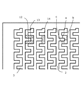
Screening media of a vibrating screen for screening fractions of stone or gravel. The screening media is formed of ribs (2, 5, 10) extending from one end of the screening media to the opposite end. Pins (3, 6) projecting perpendicular from the ribs (2, 5, 10) are placed on opposite sides of the ribs (2, 5, 10). Each pin (3, 6) ends at a distance from the adjacent rib (2, 5, 10). The dimension and placement of the pins (3, 6) are such that there will be formed a continuous aperture between two adjacent ribs (2, 5, 10). Each aperture is formed of a number of rectangular screening areas (12, 13, 14) of identical size. Each screening area (12, 13, 14) is placed perpendicular to each adjacent screening area (12, 13, 14) and end areas of adjacent screening areas (12, 13, 14) coincide.


French Abstract

L'invention concerne un moyen de tamisage d'un tamis vibrant servant à tamiser des fragments de pierre ou de gravier. Le moyen de tamisage est formé de nervures (2, 5, 10) s'étendant d'une extrémité du moyen de tamisage jusqu'à l'autre extrémité. Des ergots (3, 6) en saillie perpendiculairement aux nervures (2, 5, 10) sont placés sur les côtés opposés des nervures (2, 5, 10). Chaque ergot (3, 6) se termine à une certaine distance de la nervure (2, 5, 10) adjacente. La dimension et le positionnement des ergots (3, 6) sont tels qu'une ouverture continue se formera entre deux nervures (2, 5, 10) adjacentes. Chaque ouverture est formée d'un certain nombre de zones de tamisage rectangulaires (12, 13, 14) de taille identique. Chaque zone de tamisage (12, 13, 14) est placée perpendiculairement à chaque zone de tamisage (12, 13, 14) adjacente et les zones d'extrémité de zones de tamisage (12, 13, 14) adjacentes coïncident.

Claims

Note: Claims are shown in the official language in which they were submitted.


6
CLAIMS
1. Screening media of a vibrating screen for screening fractions of stones or
gravel, whereby the screening media is formed of ribs (2, 5, 10) extending
from one end
of the screening media to an opposite end and whereby pins (3, 6) project
perpendicular
from the ribs (2, 5, 10) on opposite sides of each rib (2, 5, 10), ending at a
distance from
the adjacent rib (2, 5, 10), wherein a pin (3) projecting from one rib (2, 5,
10) is
positioned in the middle between two pins (3) projecting from the adjacent rib
(2, 5, 10),
and wherein the dimension and placement of the pins (3, 6) are such that there
will be
formed a continuous aperture between two adjacent ribs (2, 5, 10), wherein the
pins (3,
6) on each side of the ribs (2, 5, 10) are placed with even spacing and the
distance (a)
between adjacent pins (3) on adjacent ribs is the same as the distance (b)
between the
free end of each pin (3) and the adjacent rib (2, 9) and the distance (c) with
which two
adjacent pins (3) on adjacent ribs (2) extend past each other, and wherein
each rib (5, 10)
is raised above an upper surface of each pin (6).
2. The screening media of claim 1, wherein each rib (10) has a rounded upper
surface as seen in cross section.
3. The screening media of claim 1 or 2, wherein each rib (2, 5, 10) extend in
the
direction (15) of motion of matters to be screened.
4. The screening media of any one of claims 1 to 3, wherein each rib (10) has
a
reinforcement (16) placed inside the rib (10) and extending all the length of
the rib (10).
5. The screening media of claim 4, wherein the reinforcement (16) is made of a

polymeric material.
6. The screening media of any one of claims 1 to 5, wherein a bar (8, 11) is
placed in the middle of the screening panel (7, 9) with an extension
perpendicular to the
direction (15) of motion for the fraction to be screened.
7. The screening media of claim 6, wherein the upper surface of the bar (8,
11) is
flush with the upper surface of the pins (3, 6).
8. The screening media of any one of claims 1 to 6, wherein the screening
media
is made by injection moulding.
9. The screening media of claim 8, wherein the screening media is injection
moulded together with reinforcements of the ribs (2, 5, 10).

7
10. The screening media of any one of claims 1 to 9, wherein the screening
media
is a screening panel (1, 4, 7, 9).

Description

Note: Descriptions are shown in the official language in which they were submitted.


CA 02908594 2015-10-02
WO 2014/173581
PCT/EP2014/054558
1
SCREENING MEDIA
15
Technical Field
The present invention concerns screening media for a vibrating screen.
Prior Art
In vibrating screens used for fractionation of for example crushed stones and
gravel into fractions of stones with different sizes, screening media are used
having
screening holes for allowing stones smaller than the screening holes to pass
through the
holes.
The screening media is normally provided in the form of panels or mats. This
description is concentrated to panels to simplify the description, but it is
to be under-
stood to apply also for screening mats.
In WO 2012/029072 a screen panel is shown having ribs with protrusions. The
apertures forming the screening areas are essentially square in form. The
protrusions go
almost all the way between the ribs. The distance formed between the
protrusions and
the adjacent rib is to make the seal panels more resilient, whereby the ribs
may yield a
bit. This should in theory reduce the risk of clogging.
Summary
For screening media in the mining industry one always seeks high capacity,
long life and minimal maintenance requirement. The normally used square or
slotted
apertures of screening media leads to risk for blinding and not enough open
area.
The capacity of a vibrating screen is influenced by a number of factors. One
way to increase the capacity is to increase the ratio of open space in the
screening me-

CA 02908594 2015-10-02
WO 2014/173581 PCT/EP2014/054558
2
dia. Regarding the screening media it is also important that it lets the
stones through
which it is designed to be let through and that it does not clog easily. The
screening me-
dia should also be durable.
The screening media of the present invention forms a screening area that could
be said being formed of a number of rectangular areas placed mutually
perpendicular to
each other and coinciding at the ends.
Screening media with the apertures of the present invention have more open
area, compared to normal screening media of the prior art, which means higher
capacity
and reduced risk of blinding. By letting the apertures of the screening media
have slots
directed both along and traverse to the direction of movement for the material
to be
screened, particles of different shapes are more readily screened.
In some embodiments of the present invention raised bars are used, to
facilitate
for fine material to be fed down into the screen openings. The raised bars are
directed in
the direction of movement for the material to be screened.
With the unique aperture design of the present invention there will be an in-
creased open area, compared to what is normal in screening media today. The
risk for
migrating and blinding is reduced and all material is guided towards the
apertures.
Further objects and advantages of the present invention will be obvious to a
person skilled in the art, when reading the detailed description below of
embodiments of
the present invention.
Brief Description of the Drawings
The invention will be described further below by way of examples and with
reference to the enclosed drawings. In the drawings:
Figs. la and lb are a perspective view and a plan view, respectively, of a
first
embodiment of screening media according to the present invention,
Figs. 2a and 2b are a perspective view and a plan view, respectively, of a sec-

ond embodiment of screening media according to the present invention
Fig. 3 is a perspective view of a third embodiment of screening media accord-
ing to the present invention,
Fig. 4 is a perspective view of a fourth embodiment of screening media ac-
cording to the present invention,
Fig. 5 is a plan view of a part of the screening media of Fig. 1, and
Fig. 6 is a cross sectional view of the screening media of Fig. 4.

CA 02908594 2015-10-02
WO 2014/173581 PCT/EP2014/054558
3
Detailed Description of Embodiments
In Figs. 1, 2, 3 and 4 different embodiments of screening panels according to
the present invention are shown. All embodiments of the present invention has
one fea-
ture in common and that is the shape of the apertures through which the
fractions
smaller than a predetermined size are to fall. Said shape of the apertures
will be dis-
cussed further in connection with Fig. 5.
In the first embodiment shown in Figs. la and lb the screening media is in the

form of a screening panel 1. It is formed of a number of parallel ribs 2,
extending from
one side to an opposite side of the screening panel 1. From the ribs 2, pins 3
project in
opposite directions perpendicular to the ribs 2. The pins 3 are placed with
even spacing
on respective side of respective rib 2. The upper surfaces of the ribs 2 and
the pins 3
projecting from them are flush with each other, thus, the upper surfaces are
in a com-
mon horizontal plane. The ribs 2 extend in the direction 15 of motion for the
matter to
be screened.
The pins 3 will have some flexibility in that they have a free outer end. This
will reduce the risk of plugging, as the pins 3 may yield to some extent.
In the area between two ribs 2, each pin 3 from one of the ribs 2 is placed in
the
middle between two pins 3 from the other rib 2. In said area between two ribs
2 pins 3
from alternating ribs 2 are placed with even spacing. The pins 3 do not
project all the
way to the adjacent rib 2, but stops at a distance from the adjacent rib 2.
However, the
pins 3 of adjacent ribs 2 project a distance past each other.
In the second embodiment shown in Figs. 2a and 2b, the screening media is in
the form of a screening panel 4. The parts of the second embodiment
corresponding
with the first embodiment will not be described extensively here. The
screening panel 4
comprises a number of parallel ribs 5 and pins 6. The ribs 5 extend from one
side of the
screening panel 4 to an opposite side of the screening panel 4. In this second
embodi-
ment the ribs 5 project above the pins 6. The ribs 5 have a rectangular cross
section. The
mutual positions of the ribs 5 and the pins 6 in relation to each other are
the same as for
the first embodiment.
The third embodiment of a screening panel 7, shown in Fig. 3, differs from the
screening panel 1 of Fig. 1 only in that a bar 8 is placed in the middle of
the screening
panel 7. The bar 8 is placed perpendicular to the direction 15 of motion for
the matter to
be screened. The upper surface of the bar 8 is flush with the upper surfaces
of the ribs
and pins of the screening panel 7. The bar 8 increases the stability of the
screening panel
7. The bar 8 will also act against deflection, which may be a problem
especially for

CA 02908594 2015-10-02
WO 2014/173581 PCT/EP2014/054558
4
relatively thin screening media. The mutual position of ribs and pins in
relation to each
other are the same for this embodiment as for the previous embodiments.
In Fig. 4 a fourth embodiment of a screening panel 9 is shown. The screening
panel 9 has raised ribs 10, projecting above the rest of the screening panel
9. The raised
ribs 10 have a curved upper surface as seen in cross section. The curvature of
the upper
surface of each raised rib 10 is such that the highest part is in the middle,
as seen in
cross section. The screening panel 9 of the fourth embodiment has also a bar
11 placed
in the middle, corresponding with the bar 8 of the third embodiment of the
screening
panel 7. The mutual position of ribs and pins in relation to each other are
the same for
this embodiment as for the previous embodiments.
By means of the design of the ribs 2, 5, 10 and the pins 3, 6, apertures are
formed between the ribs 2, 5, 10 and the pins 3, 6 in each screening panel 1,
4, 7, 9. As
stated above the apertures have the same shape irrespectively of which
screening panel
1, 4, 7, 9 it is referred to. For the discussion of the shape of the apertures
we now refer
to Fig. 5. There is a continuous aperture between two adjacent ribs 2. In the
shown em-
bodiment the apertures could be said to be formed of a number of rectangular
screening
areas 12, 13, 14 each extending perpendicularly to the adjacent screening area
12, 13,
14. The screening areas coincide at the ends. The dimensions of the ribs 2 and
the pins 3
are such that all of the screening areas 12, 13, 14 have the same area. This
is achieved in
that the distance a between two adjacent pins 3 projecting from different ribs
2 is the
same as the distance b between the free end of a pin 3 and the opposite rib 2.
Also a
distance c between planes containing the free ends of adjacent pins 3 is the
same as the
above distances a and b. Expressed differently the distance c is the distance
two adja-
cent pins 3 from adjacent ribs 2 each project past the other.
The size of the rectangular screening areas 12, 13, 14 is amended depending on
the size of the fraction to be screened. Independently of the size of the
rectangular
screening areas 12, 13, 14 they are always of the same mutual size. Thus, the
above
stated distances a, b, c may vary but are always mutually the same. In
practice it is the
size of the pins 3 that is amended if the size of the fraction to be screened
is to be al-
tered. The width of the ribs 2 do not need to be amended even if the size of
the pins 3 is
altered, but in some cases also the width of the ribs 2 is altered.
As indicated in Fig. 6 the raised ribs 10 may each have a central
reinforcement
16 going through the length of the raised rib 10. The reinforcements 16 are
made of any
suitably stiff material, including both metal and polymeric materials. Also
the raised
ribs 5 of the second embodiment may be provided with corresponding
reinforcements.

CA 02908594 2015-10-02
WO 2014/173581 PCT/EP2014/054558
The screening panels 1, 4, 7, 9 of the present invention are preferably
produced
by injection moulding.
By means of the pattern of the open areas of the screening media of the
present
invention the open area has both longitudinal and transversal directions, as
seen in the
5 direction of movement for the material to be screened. Often screening
media have only
square or rectangular screening areas. Transversal screening areas counteract
blinding
or plugging and longitudinal screening areas are beneficial for screening
flaking mate-
rial.
A person skilled in the art realizes that features of the different
embodiments
may be combined in other ways than in the embodiments shown in the Figs.

Representative Drawing
A single figure which represents the drawing illustrating the invention.
Administrative Status

For a clearer understanding of the status of the application/patent presented on this page, the site Disclaimer , as well as the definitions for Patent , Administrative Status , Maintenance Fee  and Payment History  should be consulted.

Administrative Status

Title Date
Forecasted Issue Date 2021-01-12
(86) PCT Filing Date 2014-03-10
(87) PCT Publication Date 2014-10-30
(85) National Entry 2015-10-02
Examination Requested 2019-01-14
(45) Issued 2021-01-12

Abandonment History

There is no abandonment history.

Maintenance Fee

Last Payment of $210.51 was received on 2023-02-01


 Upcoming maintenance fee amounts

Description Date Amount
Next Payment if small entity fee 2024-03-11 $125.00
Next Payment if standard fee 2024-03-11 $347.00

Note : If the full payment has not been received on or before the date indicated, a further fee may be required which may be one of the following

  • the reinstatement fee;
  • the late payment fee; or
  • additional fee to reverse deemed expiry.

Patent fees are adjusted on the 1st of January every year. The amounts above are the current amounts if received by December 31 of the current year.
Please refer to the CIPO Patent Fees web page to see all current fee amounts.

Payment History

Fee Type Anniversary Year Due Date Amount Paid Paid Date
Registration of a document - section 124 $100.00 2015-10-02
Application Fee $400.00 2015-10-02
Maintenance Fee - Application - New Act 2 2016-03-10 $100.00 2016-02-16
Maintenance Fee - Application - New Act 3 2017-03-10 $100.00 2017-02-08
Maintenance Fee - Application - New Act 4 2018-03-12 $100.00 2018-02-06
Request for Examination $800.00 2019-01-14
Maintenance Fee - Application - New Act 5 2019-03-11 $200.00 2019-02-06
Maintenance Fee - Application - New Act 6 2020-03-10 $200.00 2020-02-05
Final Fee 2020-12-07 $300.00 2020-11-13
Maintenance Fee - Patent - New Act 7 2021-03-10 $204.00 2021-02-17
Maintenance Fee - Patent - New Act 8 2022-03-10 $203.59 2022-02-09
Maintenance Fee - Patent - New Act 9 2023-03-10 $210.51 2023-02-01
Owners on Record

Note: Records showing the ownership history in alphabetical order.

Current Owners on Record
SANDVIK INTELLECTUAL PROPERTY AB
Past Owners on Record
None
Past Owners that do not appear in the "Owners on Record" listing will appear in other documentation within the application.
Documents

To view selected files, please enter reCAPTCHA code :


To view images, click a link in the Document Description column. To download the documents, select one or more checkboxes in the first column and then click the "Download Selected in PDF format (Zip Archive)" or the "Download Selected as Single PDF" button.

List of published and non-published patent-specific documents on the CPD .

If you have any difficulty accessing content, you can call the Client Service Centre at 1-866-997-1936 or send them an e-mail at CIPO Client Service Centre.


Document
Description 
Date
(yyyy-mm-dd) 
Number of pages   Size of Image (KB) 
Examiner Requisition 2019-12-17 3 211
Amendment 2020-04-06 11 336
Claims 2020-04-06 2 46
Final Fee 2020-11-13 3 75
Representative Drawing 2020-12-17 1 25
Cover Page 2020-12-17 1 58
Abstract 2015-10-02 1 81
Claims 2015-10-02 2 135
Drawings 2015-10-02 3 568
Description 2015-10-02 5 472
Representative Drawing 2015-10-02 1 94
Cover Page 2015-12-31 1 83
Request for Examination 2019-01-14 2 46
International Search Report 2015-10-02 3 88
Declaration 2015-10-02 1 12
National Entry Request 2015-10-02 4 95
Fees 2016-02-16 1 33
Assignment 2016-06-13 3 95
Fees 2017-02-08 1 33