Note: Descriptions are shown in the official language in which they were submitted.
CA 02908595 2015-10-02
WO 2014/170120 PCT/EP2014/056397
1
GYRATORY CRUSHER BEARING
15 Technical Field of the Invention
The present invention relates to a gyratory crusher bearing for carrying
a crushing head of a gyratory crusher of the type comprising an inner
crushing shell, which is supported by the crushing head, and an outer
crushing shell which is supported on a crusher frame, wherein the gyratory
crusher bearing is connectable to a bearing support arranged on the crusher
frame of the gyratory crusher.
The invention further relates to a gyratory crusher bearing
arrangement, and a gyratory crusher comprising a gyratory crusher bearing.
Still further, the invention relates to a method of mounting a gyratory
crusher bearing.
Background of the Invention
A gyratory crusher may be utilized for efficient crushing of material,
such as stone, ore, etc. into smaller sizes. The gyratory crusher is provided
with an inner crushing shell and an outer crushing shell forming between
them a crushing chamber. The inner crushing shell is arranged on a crushing
head, which is made to perform a gyratory movement to effect crushing of
material in the crushing chamber. The crushing head rests on a crushing
head bearing which transfers the forces resulting from the crushing in the
CA 02908595 2015-10-02
WO 2014/170120
PCT/EP2014/056397
2
crushing chamber from the crushing head to the frame of the gyratory
crusher. Lubricant is supplied to the bearing to achieve lubrication and
cooling
of the bearing surfaces. The lubricant may, for example, be hydraulic oil.
US 2004/0035967 discloses a gyratory crusher in which a drilled hole
supplies lubricant to a crushing head bearing. However, the amount of
lubricant supplied to the bearing is not easily controlled, which reduces the
technical life of the gyratory crusher bearing.
Summary of the Invention
An object of the present invention is to provide a gyratory crusher
bearing which has improved durability compared to those of the prior art.
This object is achieved by means of a gyratory crusher bearing for
carrying a crushing head of a gyratory crusher of the type comprising an inner
crushing shell, which is supported by the crushing head, and an outer
crushing shell which is supported on a crusher frame, wherein the gyratory
crusher bearing is connectable to a bearing support arranged on the crusher
frame of the gyratory crusher. The gyratory crusher bearing comprises a
lubricant supply channel extending through at least a part of the gyratory
crusher bearing and ending at a bearing surface of the gyratory crusher
bearing, and a lubricant drainage channel extending through at least a part of
the gyratory crusher bearing and starting at the bearing surface of the
gyratory crusher bearing, wherein at least one of the lubricant supply channel
and the lubricant drainage channel is adapted for housing a combined
mounting and lubricant passage bolt holding the gyratory crusher bearing to
the bearing support.
An advantage of this gyratory crusher bearing is that it can be provided
with a relatively large amount of lubricant, since flow of lubricant over the
bearing surface is promoted by the lubricant supply channel and the lubricant
drainage channel. Thereby, the crusher bearing is well lubricated.
Furthermore, the relatively large amount of lubricant provides cooling for the
crusher bearing, which further increases its technical life. A still further
advantage is that the gyratory crusher bearing is kept in its intended
position,
which reduces the risk that the bearing inadvertently leaves its intended
CA 02908595 2015-10-02
WO 2014/170120
PCT/EP2014/056397
3
position during operation or maintenance. By being adapted for housing the
combined mounting and lubricant passage bolt in the lubricant supply and/or
drainage channel the mechanical strength of the gyratory crusher bearing will
be kept high, since only few holes needs to be provided in the bearing.
According to one embodiment the gyratory crusher bearing is provided
with an abutment surface for co-operating with the combined mounting and
lubricant passage bolt. An advantage of this embodiment is that the gyratory
crusher bearing can be secured to the bearing support in an efficient manner.
According to one embodiment at least one of the lubricant supply
channel and the lubricant drainage channel of the gyratory crusher bearing is
provided with an abutment surface for co-operating with the combined
mounting and lubricant passage bolt. An advantage of this embodiment is that
the bearing is adapted for being efficiently held in place by the bolt,
without
requiring any advanced arrangement.
According to one embodiment the abutment surface is arranged
adjacent to a lubricant inlet of the lubricant supply channel, and/or adjacent
to
a lubricant outlet of the lubricant drainage channel.
According to one embodiment the gyratory crusher bearing is
connectable to a flow restricting orifice restricting the flow of lubricant
through
the lubricant drainage channel. An advantage of this embodiment is that the
drainage of lubricant from the bearing surface is restricted, such that the
film
of lubricant becomes thicker and more efficient at lubricating the bearing
surface.
According to one embodiment the gyratory crusher bearing in itself
includes a flow restricting orifice restricting the flow of lubricant through
the
lubricant drainage channel. An advantage of this embodiment is that drainage
of lubricant from the bearing surface is restricted, to make the film of
lubricant
thicker and more efficient at lubricating the bearing surface.
According to one embodiment the lubricant drainage channel is
adapted for housing the combined mounting and lubricant passage bolt
holding the gyratory crusher bearing to the bearing support. An advantage of
this embodiment is that it is often more efficient to mount the bolt to the
lubricant drainage channel, because the drainage channel need not be
CA 02908595 2015-10-02
WO 2014/170120
PCT/EP2014/056397
4
connected to a pressurized source of lubricant, which is the case with the
lubricant supply channel.
According to one embodiment a lubricant inlet is arranged in the
bearing surface and is connected to the lubricant supply channel, and a
lubricant outlet is arranged in the bearing surface and is connected to the
lubricant drainage channel, wherein the lubricant inlet and the lubricant
outlet
are arranged in opposite ends of the bearing surface. By "opposite ends" is
here meant that there is an angular separation of 160-200 between the
lubricant inlet and the lubricant outlet, as seen from above. An advantage of
arranging the lubricant inlet and the lubricant outlet at opposite ends of the
bearing surface is that the lubricant is made to flow a relatively long
distance
over the bearing surface, thereby making the lubrication more efficient.
According to one embodiment the bearing surface is adapted to be in
contact with a lower surface of the crushing head. An advantage of this
embodiment is that the crushing head is efficiently and steadily supported by
the gyratory crusher bearing.
According to one embodiment the gyratory crusher bearing comprises
a material selected from the group of materials consisting of: metals, metal
alloys, ceramics, polymers. These materials, used alone or in combination,
are suitable bearing materials for use in the gyratory crusher bearing.
According to one embodiment the gyratory crusher bearing forms a
"collar" adapted to encircle a crushing shaft onto which the crushing head is
mounted. This provides for particularly efficient and steady support of a
crushing head, for example in an inertia cone crusher.
According to one embodiment the bearing surface of the gyratory
crusher bearing is provided with at least one lubrication track. An advantage
of this embodiment is that it provides for improved cooling of the bearing
surface.
According to one embodiment the at least one lubrication track has a
width of 5-100 mm. According to one embodiment the at least one lubrication
track has a depth of 2-30 mm. These embodiments have the advantage of
providing for a relatively large flow of lubricant, resulting in good cooling
of the
bearing surface.
CA 02908595 2015-10-02
WO 2014/170120
PCT/EP2014/056397
According to one embodiment the at least one lubrication track extends
from a lubricant inlet to a lubricant outlet of the bearing surface. This
embodiment provides for a more efficient transport of lubricant over the
bearing surface, thereby increasing the cooling and the lubrication of the
5 bearing surface.
A further object of the present invention is to provide a gyratory crusher
bearing arrangement which has a longer technical life than those of the prior
art.
This object is achieved by a gyratory crusher bearing arrangement
comprising a gyratory crusher bearing according to one or more of the
described embodiments, the gyratory crusher bearing arrangement further
comprising a bearing support, and a combined mounting and lubricant
passage bolt arranged in at least at one of the lubricant supply channel and
the lubricant drainage channel of the gyratory crusher bearing and fixing the
gyratory crusher bearing to the bearing support.
An advantage of this gyratory crusher bearing arrangement is that it
provides for efficient lubrication, a long technical life, and reduced risks
in
conjunction with operating and maintaining a crusher to which it is
connectable.
According to one embodiment the combined mounting and lubricant
passage bolt is arranged in the lubricant drainage channel.
According to one embodiment the combined mounting and lubricant
passage bolt comprises a lubricant channel via which lubricant may pass by
the bolt. An advantage of this embodiment is that the bolt will both have the
function of being a device for holding the gyratory crushing bearing in its
position on the bearing support, and, additionally, the bolt also has the
function of being part of the lubricant channel, and allowing passage of
lubricant therethrough.
According to one embodiment the lubricant channel of the bolt is an
inner lubricant channel that extends through the centre of the bolt. An
advantage of this embodiment is that the bolt may be efficiently manufactured
and will obtain good mechanical strength. Furthermore, the inner lubricant
CA 02908595 2015-10-02
WO 2014/170120
PCT/EP2014/056397
6
channel will have predicable flow properties with regard to, for example, the
resistance to flow of lubricant therethrough.
According to one embodiment the combined mounting and lubricant
passage bolt comprises a flow restricting orifice restricting the flow of
lubricant
through the bolt. An advantage of this embodiment is that the amount and/or
pressure of the lubricant on the bearing surface can be controlled by
selecting
a suitable flow restricting orifice. Hence, the restriction to drainage of
lubricant
from the bearing surface can be easily adjusted, by selecting the bolt,
without
having to modify the bearing itself.
According to one embodiment the flow restricting orifice is formed in an
internal nut which is screwed into the lubricant channel of the bolt. This
embodiment makes it very easy to adjust and modify the restriction to
drainage of lubricant from the bearing surface, by just selecting and mounting
an internal nut with a suitably sized restriction orifice.
A further object of the present invention is to provide a gyratory crusher
which has a longer technical life than those of the prior art.
This object is achieved by a gyratory crusher comprising an inner
crushing shell, which is supported by a crushing head, and an outer crushing
shell which is supported on a crusher frame, the gyratory crusher further
comprising a gyratory crusher bearing according to any of the embodiments
described and/or a gyratory crusher bearing arrangement according to any of
the embodiments described for supporting the crushing head.
An advantage of this gyratory crusher is that it will have a long
technical life and will be easy and efficient to maintain.
According to one embodiment the gyratory crusher is of the inertia
cone crusher type in which a gyratory movement of the crushing head is
achieved by an unbalance weight. An advantage of this embodiment is that
the crushing head of an inertia cone crusher rests on a relatively large and
costly gyratory crusher bearing, which greatly benefits from the enhanced
lubrication and cooling of the present gyratory crusher bearing. Furthermore,
the fact that the bearing is secured to the bearing support greatly reduces
the
health risks associated with maintenance, since the risk is reduced that the
CA 02908595 2015-10-02
WO 2014/170120
PCT/EP2014/056397
7
crushing head inadvertently attaches to the bearing when being lifted from the
crusher.
A still further object of the present invention is to provide a method of
mounting a gyratory crusher bearing, such method being more efficient than
the methods of the prior art.
This object is achieved by means of a method of mounting a gyratory
crusher bearing for carrying a crushing head of a gyratory crusher of the type
comprising an inner crushing shell, which is supported by the crushing head,
and an outer crushing shell which is supported on a crusher frame, the
method comprising:
arranging the gyratory crusher bearing on a bearing support arranged
on the crusher frame of the gyratory crusher,
inserting a combined mounting and lubricant passage bolt into at least
one of a lubricant supply channel extending through at least a part of the
gyratory crusher bearing and ending at a bearing surface of the gyratory
crusher bearing, and a lubricant drainage channel extending through at least
a part of the gyratory crusher bearing and starting at the bearing surface of
the gyratory crusher bearing, and
tightening the combined mounting and lubricant passage bolt to press
the gyratory crusher bearing towards the bearing support.
An advantage of this method is that the gyratory crusher bearing is
mounted in a manner which provides for low health risks and a long technical
life.
Further objects and features of the present invention will be apparent
from the following detailed description and claims.
Brief description of the Drawings
The invention is described in more detail below with reference to the
appended drawings in which:
Fig. 1 is a schematic side view, in cross-section, of an inertia cone
crusher.
Fig. 2 is a perspective view, and illustrates a gyratory crusher bearing
mounted to a bearing support.
CA 02908595 2015-10-02
WO 2014/170120
PCT/EP2014/056397
8
Fig. 3 is a cross-section of the gyratory crusher bearing and the
bearing support of Fig. 2, as seen along the line III-Ill of Fig. 2.
Fig. 4 is an enlargement of the area IV of Fig. 3.
Description of Preferred Embodiments
Fig. 1 illustrates a gyratory crusher 1 in accordance with one
embodiment of the present invention. The gyratory crusher illustrated in Fig.
1
is of the inertia cone crusher type. It will be appreciated that the present
invention is applicable also to other gyratory cone crusher types. The
gyratory
crusher 1 comprises a crusher frame 2 in which the various parts of the
crusher 1 are mounted. The crusher frame 2 comprises an upper frame
portion 4, and a lower frame portion 6. The upper frame portion 4 has the
form of a bowl and is provided with an outer thread 8 which co-operates with
an inner thread 10 of the lower frame portion 6. The upper frame portion 4
supports, on the inside thereof, an outer crushing shell 12. The outer
crushing
shell 12 is a wear part which may be made from, for example, a manganese
steel.
The lower frame portion 6 supports an inner crushing shell
arrangement 14. The inner crushing shell arrangement 14 comprises a
crushing head 16, which has the form of a cone and which supports an inner
crushing shell 18, which is a wear part which may be made from, for example,
a manganese steel. The crushing head 16 rests on a spherical gyratory
crusher bearing 20. The gyratory crusher bearing 20 has an upper bearing
surface 22 which is in bearing contact with a lower surface 24 of the crushing
head 16. The bearing surface 22 of the crusher bearing 20 has an at least
partly concave shape, and the lower surface 24 of the crushing head 16 has
an at least partly convex shape. The gyratory crusher bearing 20 rests on a
bearing support 26 which is mounted on an inner cylindrical portion 28 of the
lower frame portion 6.
The crushing head 16 is mounted on a crushing shaft 30. The crushing
shaft 30 extends through the gyratory crusher bearing 20. Hence, the gyratory
crusher bearing 20 forms a "collar" encircling the crushing shaft 30.
Similarly,
also the bearing support 26 encircles the crushing shaft 30. At a lower end
CA 02908595 2015-10-02
WO 2014/170120
PCT/EP2014/056397
9
thereof, the crushing shaft 30 is encircled by a cylindrical sleeve 32. The
cylindrical sleeve 32 is provided with an inner cylindrical bearing 34 making
it
possible for the cylindrical sleeve 32 to rotate around the crushing shaft 30.
An unbalance weight 36 is mounted on one side of the cylindrical
sleeve 32. At its lower end the cylindrical sleeve 32 is connected to a
vertical
drive shaft 38. The drive shaft 38 comprises a ball spindle 40, a pulley shaft
42, an intermediate shaft 43 connecting the ball spindle 40 to the pulley
shaft
42, an upper connector 44 which connects the ball spindle 40 to the
cylindrical sleeve 32, and a lower connector 46 which is arranged on the
intermediate shaft 43 and which connects the ball spindle 40 to the inter-
mediate shaft 43. The two connectors 44, 46 are connected to the ball spindle
40 in a non-rotating manner, such that rotational movement can be
transferred from the pulley shaft 42 to the cylindrical sleeve 32 via the
intermediate shaft 43 and the ball spindle 40.
A bottom portion 48 of the lower frame portion 6 comprises a vertical
cylindrical drive shaft bearing 50 in which the vertical drive shaft 38 is
supported. A motor (not shown) is arranged for driving a pulley 52 which is
connected to the pulley shaft 42, below the drive shaft bearing 50. Lubricant
is collected at the inside of the bottom portion 48 and is returned to a
lubricant
pump (not shown) via a lubricant return pipe 49.
The outer and inner crushing shells 12, 18 form between them a
crushing chamber 51 to which material that is to be crushed is supplied. The
discharge opening of the crushing chamber 51, and thereby the crushing
capacity, can be adjusted by means of turning the upper frame portion 4, by
means of the threads 8, 10, such that the distance between the shells 12, 18
is adjusted.
When the crusher 1 is in operation the drive shaft 38 is rotated by
means of the not shown motor. The rotation of the drive shaft 38 causes the
sleeve 32 to rotate and as an effect of that rotation the sleeve 32 is swung
outwards by means of the unbalance weight 36, displacing the unbalance
weight 36 further away from the central axis C of the crusher 1, in response
to
the centrifugal force to which the unbalance weight 36 is exposed. Such
displacement of the unbalance weight 36 and of the cylindrical sleeve 32 to
CA 02908595 2015-10-02
WO 2014/170120
PCT/EP2014/056397
which the unbalance weight 36 is attached is allowed thanks to the ball
spindle 40 and thanks to the fact that the sleeve 32 may slide somewhat,
thanks to the cylindrical bearing 34, in the vertical direction along the
crushing
shaft 30. The combined rotation and swinging of the cylindrical sleeve 32 with
5 unbalance weight 36 mounted thereon causes an inclination of the crushing
shaft 30, and makes the crushing shaft 30 gyrate, such that material is
crushed between the outer and inner crushing shells 12, 18 forming between
them the crushing chamber 51.
Fig. 2 illustrates, as seen in perspective, the gyratory crusher bearing
10 20 mounted to a bearing support 26. The upper bearing surface 22 of the
bearing 20 is provided with lubrication tracks. In the embodiment shown in
Fig. 2, the bearing surface 22 is provided with a first outer lubrication
track 54,
a second outer lubrication track 56, a first inner lubrication track 58 and a
second inner lubrication track 60. Each lubrication track 54, 56, 58, 60
formed
in the bearing surface 22 may typically have a width of 5-100 mm and a depth
of 2-30 mm. The lubrication tracks 54, 56, 58, 60 extend from a lubricant
inlet
62 to a lubricant outlet 64. The lubricant inlet 62 and the lubricant outlet
64
are arranged in opposite ends of the bearing surface 22, by which is here
meant that there is an angular separation of 160-200 between the lubricant
inlet 62 and the lubricant outlet 64, as seen from above.
Hence, lubricant supplied to the bearing surface 22 enters the
lubrication tracks 54, 56, 58, 60 via the lubricant inlet 62, flows over the
bearing surface 22 in said tracks 54, 56, 58, 60, under cooling and
lubrication
of the upper bearing surface 22 and of the lower surface 24 of the crushing
head 16, shown in Fig. 1, and leaves the bearing surface 22 via the lubricant
outlet 64.
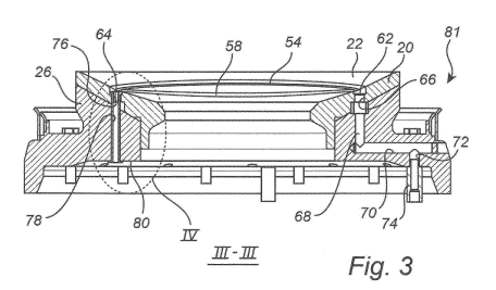
Fig. 3 illustrates the crusher bearing 20 and the bearing support 26 as
seen in cross-section along the line III-Ill of Fig. 2. The crusher bearing 20
comprises a lubricant supply channel 66. The lubricant inlet 62 is connected
to the lubricant supply channel 66 which extends through the bearing 20 and
also through the bearing support 26. In the embodiment of Fig. 3, the
lubricant supply channel 66 has a first vertical portion 68, a first
horizontal
portion 70, and a second vertical portion 72, but it will be appreciated that
CA 02908595 2015-10-02
WO 2014/170120
PCT/EP2014/056397
11
many other arrangements are possible. A lubricant supply pipe 74, which is
connected to a lubricant supply pump (not shown) is connected to the
lubricant supply channel 66, via the second vertical portion 72, such that
lubricant can be pumped to the bearing surface 22 via the lubricant inlet 62.
The crusher bearing 20 further comprises a lubricant drainage channel
76. The lubricant outlet 64 is connected to the lubricant drainage channel 76
which extends through the bearing 20 and also through the bearing support
26. A hollow combined mounting and lubricant passage bolt 78 is arranged in
the lubricant drainage channel 76 and extends from the bearing surface 22,
through the bearing 20, further through the bearing support 26, and ends
adjacent to a lower horizontal surface 80 of the bearing support 26, as will
be
described in more detail hereinafter with reference to Fig. 4. Lubricant may
be
drained from the lubricant outlet 64, through bolt 78 and to the lower surface
80 of the bearing support 26. The lubricant then passes through the lower
portion of the crusher, is collected at the bottom portion 48 shown in Fig. 1
and is, via return pipe 49, returned to the lubricant pump (not shown). When
mounted together, the gyratory crusher bearing 20, the bearing support 26
and the combined mounting and lubricant passage bolt 78 holding them
together form a gyratory crusher bearing arrangement 81 which is
connectable to a gyratory crusher.
Fig. 4 is an enlargement of the area IV of Fig. 3 and illustrates the
hollow combined mounting and lubricant passage bolt 78 in more detail. The
bolt 78 is provided with a bolt head 82, which, in the embodiment of Fig. 4,
is
arranged in a first end 84 of the bolt 78 adjacent to the bearing surface 22,
and a threaded portion 86, which, in the embodiment of Fig. 4, is arranged in
a second end 88, which is opposite to the first end 84, of the bolt 78, hence
adjacent to the lower horizontal surface 80 of the bearing support 26.
The bolt 78 is provided with an inner lubricant channel 90 which
extends all the way through the bolt 78. Hence, the inner lubricant channel 90
has a first opening 92 adjacent to bearing surface 22, and a second opening
94 adjacent to the lower horizontal surface 80 of the bearing support 26 to
allow the lubricant to pass from the bearing surface 22 and through the
bearing 20 and the bearing support 26.
CA 02908595 2015-10-02
WO 2014/170120
PCT/EP2014/056397
12
The bolt head 82 abuts an abutment surface 96 of the bearing 20. A
nut 98 is mounted to the threaded portion 86 of the bolt 78. The nut 98 has a
nut abutment surface 100 which abuts the lower horizontal surface 80 of the
bearing support 26. The nut 98 is provided with a nut opening 102 which is
fluidly connected to the inner lubricant channel 90 of the bolt 78 and which
makes it possible for lubricant to flow through the bolt 78, through the
opening
102, and further down to the bottom portion 48 illustrated in Fig. 1, and
therefrom returned to a lubricant pump.
When the nut 98 is tightened, causing the bolt head 82 to abut the
abutment surface 96 and the nut abutment surface 100 abutting the lower
horizontal surface 80, the bearing 20 will be firmly attached to the bearing
support 26. Thereby, the bearing 20 will not come loose from the bearing
support 26 during operation of the crusher. Furthermore, the bearing 20 will
remain firmly fastened to the bearing support 26 also in such a situation when
the crushing head 16 is lifted vertically upwards for maintenance.
The bolt 78 is provided with a flow restricting orifice 104. In the
embodiment of Fig. 4, the orifice 104 is formed in an internal nut 106 which
is
screwed into the inner lubricant channel 90 of the bolt 78, at the first end
84
thereof. The diameter of the flow restricting orifice 104 is chosen such that
the
lubricant cannot freely flow through the bolt 78, but has to overcome a
pressure drop caused by the orifice 104. This pressure drop will cause a
certain lubricant pressure also in the lubrication tracks 54, 56, 58, 60,
since
the latter are, during operation of the crusher and when the lower surface 24
of the crushing head 16, shown in Fig. 1, slides over the bearing surface 22,
covered by the lower surface 24. The pressure built up in the lubrication
tracks 54, 56, 58, 60 will force lubricant to spread over the bearing surface
22,
as indicated by arrows LO in Fig. 4, such that the entire bearing surface 22
is
lubricated and cooled.
It will be appreciated that numerous variants of the embodiments
described above are possible within the scope of the appended claims.
Hereinbefore it has been described that the hollow combined mounting
and lubricant passage bolt 78 is arranged in the lubricant drainage channel
CA 02908595 2015-10-02
WO 2014/170120
PCT/EP2014/056397
13
76. It will be appreciated that such a combined mounting and lubricant
passage bolt 78 may, as alternative thereto, or in combination therewith, be
arranged in the lubricant supply channel 66. Hence, in accordance with a first
embodiment a combined mounting and lubricant passage bolt 78 is arranged
in the drainage channel 76, in accordance with a second embodiment a
combined mounting and lubricant passage bolt 78 is arranged in both
channels 66, 76, and in accordance with a third embodiment a combined
mounting and lubricant passage bolt 78 is mounted in the lubricant supply
channel 66, but not in the drainage channel 76. In the latter case, a flow
restricting orifice is suitably arranged in the drainage channel 76 such that
a
suitable lubricant pressure in the lubrication tracks 54, 56, 58, 60 can be
achieved.
Hereinbefore it has been described that the flow restricting orifice 104
is provided as an internal nut 106 which is screwed into the bolt 78. It will
be
appreciated that other embodiments are also possible. For example, the flow
restricting orifice 104 could, as alternative to being provided in an internal
nut
106, be an integral part of the bolt 78. Furthermore, a flow restricting
orifice
could be formed in the actual lubricant drainage channel 76. In accordance
with one embodiment a flow restricting orifice could be formed in the channel
76 adjacent to the lubricant outlet 64, the flow restricting orifice thereby
being
an integrated part of the bearing 20. The latter may be suitable in an
embodiment in which a combined mounting and lubricant passage bolt 78 is
mounted in the lubricant supply channel 66, but not in the drainage channel
76.
Hereinbefore it has been described, with reference to Fig. 4, that the
the bolt 78 is provided with an inner lubricant channel 90 extending through
the entire length of the bolt 78, and at the centre thereof. It will be
appreciated
that other types of lubricant channels 90 could also be provided in the bolt
78.
For example, the lubricant channel need not extend all the way through the
bolt, for example, if there is an outlet connection somewhere along the length
of the bolt. Furthermore, the lubricant channel need not be arranged in the
centre of the bolt, but could be arranged in one side of the bolt.
Hereinbefore it has been described that the bolt 78 is tightened by
means of a nut 98. It will be appreciated that the bolt 78 may be tightened in
CA 02908595 2015-10-02
WO 2014/170120 PCT/EP2014/056397
14
other manners as well. For example, the bolt 78 may be tightened by the
threaded portion 86 of the bolt 78 co-operating with a threaded portion formed
in the bearing support 26, inside the drainage channel 76.
Hereinbefore it has been described that the gyratory crusher is of the
inertia cone crusher type. It will be appreciated that the principles
described
above may be applied to gyratory crushers of other types as well.