Note: Descriptions are shown in the official language in which they were submitted.
CA 02908615 2015-10-02
W02014/169397
PCT/CH2013/000063
1
TRANSPORT DEVICE
The present invention relates to a transport device, in particular, for
transporting
cooling blocks in a casting machine with caterpillar mold according to the
preamble of
patent claim 1.
Transport devices with endless belts or chains are commonly used in technology
as
conveyors. A further application of such transport devices can be found in the
foundry
industry in which, for example, the rolling members of the device may include
a
rolling member body having one or more cooling blocks so that the rolling
members
form the cooling elements of a casting caterpillar.
Casting devices of this type are known as so-called caterpillar-type mold
casting
machines and are, according to American terminology, called "machines with
caterpillar mold" and also "block casters."
By way of a drive, the blocks circulate as endless caterpillars around a
machine
body, one design including two machine bodies opposite each other which are
positioned in such a way that the distance between the walls facing one
another in
the mold corresponds to the thickness of the strand to be cast, taking into
consideration the shrinking of the molten materials as they solidify.
Another design is distinguished by the fact that the machine includes only one
machine body around which a caterpillar circulates, and the melt is poured
onto the
caterpillar where it continuously solidifies into a strand. In this instance,
the solidified
strand is preferably covered by a gas shrouding to prevent unwanted oxidation
on the
free upper side of the solidified melt.
Methods and devices for this purpose have already been developed in the
penultimate century and the last century. Reference is made to the books by E.
Hermann, "Handbuch des Stranggiessens" ("Handbook on Continuous Casting"),
1958, and "Handbook on Continuous Casting," 1980 (Aluminium Verlag
Dusseldorf).
Thus, among other types, casting machines were also designed in which the
casting
CA 02908615 2015-10-02
A WO 2014/169397
PCT/CH2013/000063
2
mold, where the melt solidifies, is formed by strung-together metal blocks
extending
over the width of the casting mold.
In order to minimize friction between the solidifying casting material and the
casting
mold, the blocks move along with the solidifying strand at the same speed
until they
reach the end of the casting mold, where they are detached from the strand and
are
directed, for example, by means of chain wheels or arcuate running paths to
the rear
of the machine body and are, after undergoing a change of direction once more,
guided back to the inlet of the casting mold.
A casting machine, the cooling elements of which form the wall of a casting
mold on
the straight portions of the casting caterpillars, is known from WO
2005/068108
LAMEC. This known casting machine includes two casting caterpillars, each of
the
two casting caterpillars forming a wall of the casting mold and each casting
caterpillar
being made up of a plurality of endless cooling blocks connected to one
another. The
cooling blocks are installed on carrier elements, which are mounted on chains
and
thus are movably connected to one another like links of a chain. For this
purpose, the
cooling blocks hold, by way of stationary magnets, the supporting members on
the
chains, from which they would fall down because of gravity. The chain links
are
provided at their junctions with rollers rolling on guide paths. This known
molding
machine, however, has the disadvantage that, in particular, significant
friction losses
are caused by the chain joints under load owing to the caterpillar drive
In this instance, the object of the invention is to remedy this circumstance.
The object
of the invention is to create a transport device, the roller elements of which
enable a
low-friction, uninterrupted run on the entire circulating path and, in
particular, in the
deflection arcs and when transitioning between the straight sections and the
deflection arcs.
The invention solves this problem by a transport device which has the
characteristics
of claim 1.
The advantages achieved by the invention are substantially to be seen in that:
CA 02908615 2015-10-02
W02014/169397
PCT/CH2013/000063
3
- Since each roller element by means of rollers is individually directed in
the
guide paths on the circulating path and, thus, may not fall down from the
guide
paths because of gravity, the roller elements do not have to be coupled to one
another in the direction of the circulation movement. For this reason, a low-
friction, uninterrupted run of the roller elements on the circulating path
and, in
particular, in transitions and on the deflection arcs is enabled; and
- The detached roller elements may be deposited or stacked on specially
designed depositing stations for the reception of the roller carriers without
the
rolling elements tipping.
Additional advantageous embodiments of the invention may be commented upon as
follows:
In one specific embodiment, the roller elements are loose relative to one
another in
the direction of the circulation movement. For this reason, the advantage may
be
achieved that applying and removing the roller elements may occur individually
or in
assemblies without having to loosen connections between the individual roller
elements because the roller elements succeeding one another on the circulating
path
are not coupled together like the links of a chain. Particularly when using
the
transport device in casting machines with caterpillar mold, the roller
elements
designed as cooling elements may be placed on and removed from the machine
with
minimal time effort.
In another embodiment, joint bearings are situated in the area of the first
end and/or
in the area of the second end of the roller element body, wherein in each case
at
least two rollers are attached to a joint bearing.
Preferably, the joint bearings are rotatably attached to the roller element
body by way
of joint axles, wherein the joint axles are perpendicularly positioned to a
center plane
of the transport device defined by the circulating path U.
In a further embodiment, the rollers respectively include a roller axle,
wherein the
roller axles are fixedly attached to the roller element body.
CA 02908615 2015-10-02
WO 2014/169397
PCT/CH2013/000063
4
In another embodiment, the roller element bodies measured in the direction of
circulation have a maximum length "L" and immediately adjacent roller elements
may
be positioned on the first and second guide path in such a manner that the
geometric
axes of the roller axles or of the joint axles of the rollers or joint
bearings, which are
disposed in the area of the first ends of two adjacent roller elements, may be
substantially adjusted to a distance, which corresponds to the maximum length
"L".
In yet another embodiment, the geometrical axes of the roller axles or of the
joint
axles of the rollers or joint bearings disposed in the area of the first ends
lie in a plane
orthogonal to the direction of the circulation movement, which plane is
defined by the
first end of the respective roller element body.
In a further embodiment, the geometrical axes of the roller axles or of the
joint axles
of the rollers or joint bearings disposed in the area of the second ends lie
in a plane
orthogonal to the direction of the circulation movement, having a distance to
the
plane defined by the first ends of the respective roller element body which is
substantially equal to or greater than the length "L". In this way, the
advantage may
be achieved that the axle distance substantially corresponds to the cooling
block
length measured in the direction of circulation, as a result of which a
kinematically
optimal run of the cooling blocks on the entire circulating path is enabled.
Preferably, the geometrical axes of the roller axles or of the joint axles,
which are
situated at the first and second ends facing each other of two roller elements
adjacent in the direction of the circulation movement, are substantially
coaxial. The
coaxial arrangement of the geometrical axes of the rollers of two adjacent
roller
elements, which are situated at the ends of the roller elements facing each
other,
together with the geometry of the guide paths results in a kinematically
optimal run of
the roller elements via the circulating path U. In particular, in using the
transport
device in casting machines with caterpillar mold, the edges of the cooling
blocks do
not enter the casting plane when transitioning to the deflection arcs.
In another embodiment, each roller element body includes at least one cooling
block
so that a casting caterpillar is formed which is suitable as a wall for a
casting mold. In
CA 02908615 2015-10-02
,
WO 2014/169397
PCT/CH2013/000063
,
this instance, the cooling blocks may be, according to the required operating
conditions, made of antimagnetic or ferromagnetic material, preferably copper
or
aluminum, as well as cast iron or steel.
In yet again another embodiment, the cooling blocks have a bottom side facing
the
rollers and a flat cooling surface on the opposite side and the two parallel
planes
including the geometrical axes of the roller axles or of the joint axles are
perpendicular to the cooling surface. In the case that the flanks of the
cooling blocks
are curved, the two planes are defined by the perpendiculars of the edges of
the
cooling blocks lying in the casting plane, the perpendiculars being vertical
to the
cooling surface.
In a further embodiment, each roller element includes at least four rollers,
wherein
respectively two rollers are disposed at the first and second ends of each
roller
element body, and the rollers disposed at the first end are orthogonally
offset to the
center plane vis-à-vis the rollers disposed at the second end. In doing so,
the
advantage can be achieved that the rear rollers of a cooling element are
offset in the
lateral direction vis-à-vis the front rollers of the adjacent cooling element
in such a
manner that the cooling elements are able to be pushed together in the
direction of
motion (in the direction of the circulation movement) until the flanks of the
cooling
elements touch. Preferably, the two rollers disposed at the first end have a
distance A
and the two rollers disposed at the second end have a distance B 0 A to each
other,
and the distances A and B are sized so that the two rollers disposed at the
first end fit
between the rollers disposed at the second end of the adjacent roller element.
Thus,
the advantage may be provided that the geometrical axes of the rollers of a
cooling
element disposed at the first end are collinear with the geometrical axes of
the rollers
of the adjacent cooling element disposed at the second end.
In a further embodiment, the guide paths have at least in one portion of the
circulating path U, in which the roller elements would, owing to gravity, fall
down from
the guide paths, first and second roller running surfaces, which are situated
opposite
each other.
CA 02908615 2015-10-02
WO 2014/169397
PCT/CH2013/000063
6
In a further embodiment, the guide paths have deflection arcs, wherein the
guide
paths include in the area of the deflection arcs first and second roller
running
surfaces situated opposite each other in the radial direction so that the
rollers roll on
the first or the second roller running surface, depending on the direction of
the load.
The advantage of this embodiment is in that the cooling elements, as a
consequence
of gravity, are not able to tilt away from the guide paths or fall down
therefrom.
Preferably, the guide paths respectively include a first and/or second roller
running
surface directed towards the center plain and a first and/or second roller
running
surface directed away from the center plane.
In another embodiment, the roller element bodies of the roller elements are
designed
as cooling blocks and the rollers are attached to the cooling blocks.
In yet another embodiment, the roller element bodies of the roller elements
include a
roller carrier.
In a further embodiment, a multiple of cooling blocks are situated on each
roller
carrier perpendicular to the center plane. In doing so, the influences from
thermal
expansions and stress from cooling blocks and roller carriers (transport
carriers) may
be minimized to secure the planeness of the casting surface and to reduce the
wear
of the machine elements caused by thermal stresses. The machine elements
unidirectionally impinged with heat have a natural tendency, such as the
cooling
blocks and the roller carriers placed thereunder, to bend as a consequence of
thermal expansions. In order to counteract this circumstance, the beamlike
cooling
blocks extending over the width of the casting mold have, in the past, been
clamped-
down onto very flexurally rigid carriers. In a further solution, the cooling
blocks are
divided into relatively small pieces (cooling block segments), as it is
described in the
publication US 3,570,586. Since in the second solution mentioned above, the
requirement for a flexural rigidity of the carriers over the entire width of
the casting
surface is omitted, the casting plane may also be built-up laterally by
cooling block
segments provided with rollers or by a number of individual cooling block
carrier
elements equipped with cooling block segments and provided with rollers by
stringing
said segments together in the respectively required width, wherein their heat
induced
CA 02908615 2015-10-02
W02014/169397
PCT/CH2013/000063
7
distortions, as a result of their relatively small lateral expansion, may be
kept within
limits tolerable for the casting process, even in the case of lighter
constructions. In
this instance, the roller carrier elements may carry one or more cooling
blocks. In
doing so, roller carriers and cooling blocks laterally pushed together in a
gapless
manner form the width of the casting plane. In addition to the circumstance
that the
division of the roller carriers over the width of the casting plane into
individual, short
roller carrier elements minimizes possible distortions of said carriers, the
modular
architecture of the casting width is thus also provided.
In a further embodiment, the drive device has at least one driver wheel.
Preferably, the guide paths include at least two deflection arcs, wherein in
the area of
each deflection arc respectively a driver wheel is disposed on both sides of
the center
plane. This may achieve the advantage that in the area of the circulating path
where
the roller carriers are guided on a straight line, the cooling blocks touch at
their flanks
and, in doing so, push one another when moving.
In another embodiment, the rollers of a roller element, the geometrical axes
of which
lie on a common straight line, or the mechanical axles of these rollers have
extensions perpendicular to the center plane and the driver wheels have
recesses on
their periphery, which may engage with the extensions. In this embodiment it
is
advantageous that each roller carrier in each of the two deflection arcs of
the guide
paths is driven individually by a driver wheel so that in the straight
sections of the
guide paths, where the driver wheels do not engage with the roller carriers,
the
trailing cooling block pushes the cooling block in the lead at their common
touching
surface forward.
In another embodiment, each guide path includes, viewed in a vertical
direction
parallel to the local gravity vector, an upper and a bottom guide path
section, wherein
at least the upper guide path section has only one or a multiple of first
roller running
surfaces. In doing so, the advantage may be achieved that the cooling elements
for
horizontally situated casting caterpillars on the upper, straight guide path
section¨
respectively, on the upper deflection arc for vertically situated casting
caterpillars¨
b CA 02908615 2015-10-02
WO 2014/169397
PCT/CH2013/000063
,
8
may be individually or in assemblies detached from the guide paths or be
mounted
onto said path. In this area of the circulating path in which the roller
carriers naturally
do not tilt or fall off the rails because of gravity, the guide paths do not
require any
counter holding roller running surface.
In yet another embodiment, each guide path includes a deflection arc, which
has in a
vertical direction parallel to gravity in the upper section a first opening in
the second
roller running surface oriented towards the center plane and a second opening
in the
second roller running surface oriented away from the center plane, wherein the
distance between the first opening and the second opening measured in the
direction
of the circulation movement of the roller elements corresponds to the
distance,
measured in the direction of the circulation movement, of the geometrical axes
of the
rollers situated at a roller element. The rollers of the cooling element
situated in this
area of the deflection arc, thus, may be guided through the openings so that
the
cooling element may be removed from the guide path or be introduced into said
path.
In doing so, the cooling elements may be simply removed or installed.
In a further embodiment, the transport device has a longitudinal axis and the
guide
paths are telescopic in the direction of these longitudinal axes so that
between
adjacent roller elements a space may be created, which enables the removal of
a
roller element from the guide paths.
Preferably, the roller running surfaces of each guide path have first and
second
sections moveable relative to each other, which overlap in the direction of
the
circulation movement.
In another embodiment, the guide paths include respectively a deflection arc
mounted in a rotatable manner, wherein the rotatably mounted deflection arcs
are
symmetrically disposed in respect to the center plane and may be rotated about
a
rotation axis orthogonal to the center plane.
CA 02908615 2015-10-02
WO 2014/169397
PCT/CH2013/000063
9
Preferably, the rotation axis connects the edges of the second roller running
surfaces
at the connection location between the rotatably mounted deflection arcs and
the
bottom, straight guide path sections adjacent thereto.
In a further embodiment, respectively a driver wheel is rotatively fixedly
attached to a
drive axle on each side of the center plane in the area of the deflection arcs
of the
guide paths, wherein respectively a drive axle is coaxially situated to a
geometrical
axis of the deflection arcs. In doing so, the advantage may be achieved that
the
cooling elements in the area of the deflection arcs are driven individually by
the driver
wheels and are, for this reason, not pressed together in the direction of the
circulation
movement.
In another embodiment, the roller elements are not coupled to one another in
the
direction of the circulation movement.
Preferably, the transport device according to the invention is used as a
casting
caterpillar. In particular, a transport device according to the invention may
be used as
a base module of a modularly constructed casting caterpillar of a casting
machine. In
doing so, the advantage may be achieved that the width of the casting surface
may
be laterally built-up by constructively stringing together identical modules.
The invention and further refinements of the invention are subsequently
described in
more detail on the basis of the partially schematic illustrations of a
plurality of
exemplary embodiments.
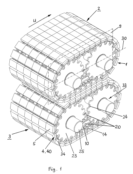
Fig. 1 shows a perspective view of an embodiment of the transport device
according to the invention, wherein respectively one transportation device
forms a base module of a casting caterpillar of a casting machine;
Fig. 2 shows a perspective view of a multiple of roller elements according
to the
embodiment of the transport device according to the invention illustrated in
Fig. 1;
CA 02908615 2015-10-02
WO 2014/169397
PCT/CH2013/000063
Fig. 3 shows a perspective view of a roller element designed as a cooling
element
according to another embodiment of the transport device according to the
invention;
Fig. 4 shows a perspective view of the guide paths according to a further
embodiment of the transport device according to the invention;
Fig. 5 shows an enlarged illustration of the detail A in Fig. 4;
Fig. 6 shows a perspective view of a module of a casting caterpillar
according to
the embodiment of the transport device according to the invention illustrated
in Fig. 1;
Fig. 7 shows a perspective explosive view of a casting caterpillar
including three
modules according to the embodiment of the transport device according to
the invention illustrated in Fig. 1;
Fig. 8 shows a perspective view of a module of a casting caterpillar
according to
the in Fig. 1 illustrated embodiment of the transport device according to the
invention having partially removed cooling blocks and two tilted roller
carriers;
Fig. 9 shows a perspective view of a module of a casting caterpillar
according to
yet another embodiment of the transport device according to the invention;
Fig. 10 shows an enlarged view of detail C in Fig. 9;
Fig. 11 shows a perspective view of a guide path of a casting caterpillar
according
to yet again another embodiment of the transport device according to the
invention having enclosed guide paths;
CA 02908615 2015-10-02
=
WO 2014/169397
PCT/CH2013/000063
11
Fig. 12 shows a perspective view of the guide paths of the casting caterpillar
according to the embodiment of the transport device according to the
invention illustrated in Fig. 11 having open guide paths; and
Fig. 13 shows a lateral view of a roller element according to another
embodiment of
the transport device according to the invention.
The transport device 1 according to the invention is here exemplary described
in its
use in a casting machine with caterpillar mold. In the embodiment illustrated
in Fig. 1,
the transport device 1 is provided with roller elements 4, whose roller
element body
34 includes, for example, a cooling block 5 so that the roller elements 4 form
the
cooling elements 40 of a casting caterpillar 2, 3. The roller elements 4
designed as
cooling elements 40 form the wall of a casting mold on the straight sections
of the
casting caterpillars 2, 3. Further, the transport device 1 includes a drive
device 33
having driver wheels 23 for moving the roller elements 4.
The embodiment illustrated in Fig. 1 includes two casting caterpillars 2, 3,
which are
positioned horizontally and above one another. Alternatively, casting machines
may
also be produced having vertically situated or inclined casting caterpillars
2, 3. Each
of two casting caterpillars 2, 3 includes, for example, six transport devices
1
positioned next to one another, wherein each transport devices 1 forms a base
module 32 of a modularly constructed casting machine. Each transport device 1
includes two guide paths 20, which extend over an oval circulating path U and
which
are situated symmetrically in respect to a center plane 9. A multiple of
roller elements
4 circulate in a caterpillar-like manner on the guide paths 20. Each roller
element 4
includes a roller element body 34, which has a first end 35 and a second end
36 in
the direction of the circulation movement. Further, at each roller element 4
four rollers
10, for example, are attached. The roller elements 4 are arranged loosely to
one
another in the direction of the circulation movement, that is, they are not
coupled to
one another. The circulation movement of the roller elements 4 on the
circulating
path U may occur in the clockwise direction or in the counterclockwise
direction,
wherein the roller elements 4 on the first and second casting caterpillar 2, 3
circulate
in opposite directions.
CA 02908615 2015-10-02
,
WO 2014/169397
PCT/CH2013/000063
,
12
,
,
In the embodiment illustrated in Fig. 2, the cooling blocks 5 are fixed onto
individual
transport carriers, that is, are not coupled together, which are provided with
rollers 10
and subsequently referred to as roller carriers 6. The rollers 10 run on and
in guides,
which are designed as guide paths 20, so that the roller carriers 6 and the
cooling
blocks 5 fixed thereon move in a guided and low friction manner on the
circulating
path U. The cooling blocks 5 may, for example, be releasably attached by
screwed
connections on the roller carriers 6. Alternatively, the cooling blocks 5
themselves
may be provided with rollers 10 (Fig. 3) so that no separate roller carriers 6
are
required.
In order to enable an even, undisturbed run of the cooling blocks 5, the
rollers 10
attached to each roller carrier 6 are, viewed in the direction of motion,
situated in
such a manner that their geometrical axes lie on two parallel straight lines
11a, 11b.
Thereby, the first straight line lla is positioned in the area of the first
end 35 of the
roller element body 34 and the second straight line llb in the area of the
second end
36. Preferably, respectively a straight line 11 a, 11 b lies in a plane which
each is
defined by the first and second ends 35, 36 of each cooling block 5. The
cooling
blocks 5 have a bottom side facing the rollers 10 and, on the opposite side, a
flat
cooling surface 37 (Fig. 2). For this reason, in cuboidal cooling blocks 37,
the first
straight line 11a lies in the plane defined by front cooling block flank 7 and
the
second straight line llb lies in the plane defined by rear cooling block flank
8. In
cooling blocks 5 tapered toward the rollers 10, both planes are defined by the
edges
delimiting the cooling surface 37 of a cooling block 5 in the circulation
direction and
the respective perpendiculars to the cooling surface 37.
Thus, the axle distance of the rollers 10 just corresponds to the cooling
block length
measured in the direction of the circulation movement. Furthermore, the
rollers 10 of
the roller carriers 6 situated at the second end 36 are offset in axial
(lateral direction)
to the casting machine 1 vis-a-vis the rollers 10 of the roller carriers 6
situated at the
first end 35 in such a manner that the roller carriers 6 may be pushed
together in the
direction of motion until the flanks of the cooling blocks 5 touch and, in
doing so, the
second straight line 11 b, on which lie the geometrical axes of the rollers 10
of a roller
CA 02908615 2015-10-02
I
WO 2014/169397
PCT/CH2013/000063
13
carrier 6 situated at the second end 36, overlaps with that first straight
line 11 a, on
which lie the geometrical axes of the rollers 10 of the adjacent roller
carrier 6 situated
at the first end 35. Each roller 10 of a roller carrier 6 moves along on a
guide path of
its own. This arrangement together with the geometry of the guide path results
in a
kinematically optimal run of the cooling blocks 5 via the circulating path U.
Each roller
carrier 6 has on a straight line 11a, llb the geometrical axis of at least one
roller 10.
In a further embodiment (Fig. 13), the roller elements 4 are designed in such
a
manner that joint bearings 41 are situated in the area of the first end 35 and
in the
area of the second end 36 of the roller element body 34 and that respectively
at least
two rollers 10 are attached at the joint bearings 41. The joint bearings 41
are
rotatably attached by way of joint axles 42 at the roller element body 34,
wherein the
joint axles 42 are situated perpendicular to a center plane 9 defined by the
circulating
path U (Fig. 1) of the transport device. The geometrical axes of the joint
axles 42 of
the joint bearings 41 situated in the area of the first end 35 lie
respectively in a first
plane orthogonal to the direction of the circulation movement, which is
defined by the
first end 35 of the respective roller element body 34. The geometrical axes of
the joint
axles 42 of the joint bearings 41 situated in the area of the second end 36
lie
respectively in a second plane orthogonal to the direction of the circulation
movement, having a distance to the first plane defined by the first end 35 of
the
respective roller element body 34 which here, for example, is equal to the
maximum
length "L" of the roller element body 34. The axle distance of the joint
bearings 42
here also substantially corresponds to the cooling block length "L" measured
in the
direction of circulation, as a result of which a kinematically optimal run of
the roller
elements 4 on the entire circulating path is enabled.
As can be seen from Fig. 4 and 5, the roller guides, which are designed as
guide
paths 20, are designed in the areas of the deflection arcs 21, where the
roller carriers
6 as a result of gravity would tilt away from or fall off said arcs, so that
they have first
and second roller running surfaces 12a, 12b situated opposite each other, the
distance of which is tolerated so that the rollers 10 touch, depending on the
direction
of the load, on the first or second roller running surface 12a, 12b and roll
thereupon.
CA 02908615 2015-10-02
WO 2014/169397
PCT/CH2013/000063
14
Guide paths 20 fulfilling these conditions are preferably designed as profiled
rails.
Those pairs of rollers 10, the geometrical axles of which sit on the same
straight line
11 a, lib, are mounted in an offset manner opposite each other and run on
first and
second roller running surfaces 12a, 12b situated parallel to each other. The
guide
paths 20 may be designed on one or more profiled rails. In the embodiment
illustrated in Fig. 4, each of the two parallel guide paths 20 includes a
separate
profiled rail and respectively a first and/or second roller running surface
12a, 12b
oriented towards the center plane 9 and a first and/or second roller running
surface
12a, 12b oriented away from the center plane 9. Suitable profiled rails are: U
profile
for each roller path, U profile having two adjacent running paths, double T
profile
having respectively one roller running surface 12a, 12b on the left side and
one on
the right side of the center bar. Each guide path 20 thus includes
respectively at least
one roller running surface 12a, 12b for the rollers 10 situated at the first
end 35 of a
roller element 34 and for the rollers 10 offset in reference to the center
plane 9 at the
second end 36 of the same roller element body 34. Alternatively, a profiled
rail may
include both parallel guide paths 20. Suited for this purpose are profiled
rails which
are designed as double L profiles, double U profile or also as double T
profiles.
In this instance, the two rollers 10 situated at the first end 35 have a
distance A (Fig.
3) to each other and the two rollers 10 situated at the second end 36 have a
distance
6>A to each other, wherein the distances A and B are sized in such a manner
that
the two rollers 10 situated at the first end 35 fit between the two rollers 10
situated at
the second end 36 of the adjacent cooling element 40.
In the area of the deflection arcs 21 of the guide paths 20 driver wheels 23
are
mounted, the rotation axis of which concurs with the geometrical axis of the
deflection
arcs 21. Respectively two driver wheels 23 are symmetrically to the center
plane 9
and rotatively fixedly attached onto a drive axle 25, wherein respectively a
drive axle
25 is situated coaxially to the geometrical axis of the deflection arc 21. The
roller
carriers 6 have lateral extensions 14 at one or more of their rollers 10 or
roller axles,
which engage as drivers, for example, in the form of rollers mounted on the
respective axle, into the recesses 24 of the driver wheels 23, which in this
manner
actuate the roller carriers 6 with their cooling blocks 5.
CA 02908615 2015-10-02
,
WO 2014/169397
PCT/CH2013/000063
,
As illustrated in Fig. 4 and 5, each guide path 20 includes, viewed in a
vertical
direction parallel to gravity, an upper and a bottom straight guide path
section 27a,
27b, wherein the upper straight guide path section 27a may, in the vertical
direction
on the same height in relation to the central plane 9, have situated next to
one
another a first roller running surface 12a oriented towards the center plane 9
and a
first roller running surface 12a oriented away from the center plane 9. In
this instance,
the first roller running surfaces 12a situated next to each other have only at
one guide
path 20 a guide path section 27a provided with a side guide 44 (Fig. 5) so
that the
cooling elements 40 may expand in the area of the casting mold transversely to
the
center plane 9.
Applying and removing the cooling blocks 5 together with the roller carriers 6
may be
carried out individually or in assemblies. This occurs in the area of the
circulating
path, where the roller carriers 6 because of gravity naturally do not tilt or
fall off the
guide paths 20 and which do not require any counter holding second roller
running
surface 12b.
A difficulty, however, results from the kinematic requirement that the
distance of the
straight lines 11a, llb including the geometrical axes of the rollers 10
equates to a
cooling block length. The first cooling element 40, which is to be lifted out,
gets stuck
in the places between the remaining cooling blocks and the cooling block 5 to
be
removed because the rollers 10 of the cooling element 40, which is to be
removed,
protrude by half of a diameter under the cooling blocks 5 of the remaining
cooling
elements 40. Removing a first cooling element 40 may be carried out according
to
one of the following methods:
1) In case that the cooling blocks 5 are fixed to roller carriers 6 (Fig. 2),
it suffices
to remove the cooling blocks 5 from two to three successive cooling elements
40, as a result of which the roller carriers 6 may be tilted, pushed together
and
removed (Fig. 8).
CA 02908615 2015-10-02
,
WO 2014/169397
PCT/CH2013/000063
16
,
2) In the upper area of the deflection arc 21 (Fig. 4 and 5), in which the
cooling
blocks 5 are spread apart, in the area of the rollers 10 higher situated a
first
opening 28 in the second roller running surface 12b and, in the area of
rollers
situated further below, a second opening 29 in the second roller running
surface 12b are created, which each have at least the length of a roller
diameter. The rollers 10 of the respective cooling element 40 fit through the
first and second openings 28, 29 of the two guide paths 20 and enable the
removal of the entire cooling element 40. In the embodiment illustrated in
Fig.
4 and 5, the first openings 28 for the rollers 10 situated at the second end
36
having a smaller distance A are located at the second roller running surfaces
12b oriented towards the center plane 9 and the second openings 29 for the
rollers 10 situated at the first end 35 having a greater distance B are
located at
the second roller running surfaces 12b oriented away from the center plane 9.
In the case that the roller elements are arranged in an opposite manner and
the rollers 10 situated at the first end 35 have the smaller distance A, the
first
and second openings 28, 29 are arranged in reversed order.
3) Opening and pushing apart telescopic guide paths 20 in the direction of the
longitudinal axis 30 of the transport device 1 results in a gap in the
assembly
of rows of the cooling elements 40. If the dimension of the gap is equal to at
least the diameter of a roller 10, the rollers 10 may be pushed out
sufficiently
far from below of its adjacent cooling element 40 so to prevent that the
rollers
10 interlock with the adjacent cooling elements 40 during extraction.
The separation of guide paths 20 may be situated in straight guide path
sections 27a, 27b (Fig. 9 and 10). The roller running surfaces 12a, 12b of
each
guide path 20 have in the direction of the longitudinal axis 30 of the
transport
device 1 first and second sections 38, 39 movable relative to each other so
that the first and second sections 38, 39 of the roller running surfaces 12a,
12b
overlap in the direction of the circulation movement. When the guide paths 20
are pushed apart manner in the direction of the longitudinal axis 30 of the
transport device 1, the rollers 10 of the roller elements 4 then rest in the
region
of the separation location of the guide paths 20 on one of the first or second
sections 38, 39 of the roller running surfaces 12a, 12b.
CA 02908615 2015-10-02
WO 2014/169397
PCT/CH2013/000063
17
Alternatively, the transition location may, by pushing a deflection arc 21
aside,
be opened sufficiently wide between the straight guide path sections 27a, 27b
and the deflection arcs 21 to create the desired gap. In doing so, the
deflection
arcs 21 may be pushed aside in a translative manner from the straight guide
path sections 27a, 27b,
or
the deflection arcs 21 may be mounted in a rotatable manner at a rotation axis
31 (Fig. 11 and 12) connecting the points in which the second roller running
surfaces 12b of the deflection arcs 21 meet with the bottom second roller
running surfaces 12b of the straight guide path sections 27b. Tilting away the
deflection arcs 21 by a respective angle results in the desired path gap at
the
upper connection location, that is, in that location where the upper straight
guide path sections 27a meet with the deflection arcs 21 leading downwards.
Since the rotation axis is located at the connection location of the second
roller
running surface 12b between the deflection arcs 21 and the bottom straight
guide path sections 27b, the bottom guide path connections remain gapless
during titling so that none of the cooling elements 40 may fall off the guide
paths 20.
The requirements in reference to the width of the products to be cast are
variable and
range from under 200 mm to over 2 m. The modular architecture of the casting
machines, which meet with the different requirements in respect to the width
of the
casting product, simplifies the construction, installation and storing of
spare parts and
creates equal functionality of mechanics and operating requirements across the
entire width of the casting plane. In order to setup casting machines having
different
widths, base module 32 (Fig. 6 and 7) are configured so that by laterally
stringing
together said modules casting machines having different casting widths are
created.
A base module 32 (Fig. 6) is characterized in that it includes regarding its
width a
cooling element 40, provided with rollers 10, for example, a roller carrier 6
having one
or more cooling blocks 5, deflection arcs 21 and straight guide path sections
27a,
27b, having that number of roller running surfaces 12a, 12b, which correspond
to the
CA 02908615 2015-10-02
WO 2014/169397
PCT/CH2013/000063
18
number of rollers 10 of the cooling element 40. To the right and the left of
the outer-
most deflection arc guides, respectively a driver wheel 23 is positioned in a
concentric manner with the deflection arc guides. For this purpose, the driver
wheel
recesses 24 are oriented in a parallel manner to the axes of the deflection
arc guides.
Deflection arc guides and driver wheels 23 have in the area of their axes an
opening
through which a drive shaft 25 may be pushed, whose length is sized so that it
is able
to receive the number of base modules 32 determining the casting width. A
concentric and interlocking connection of the drive shaft 25 with the driver
wheels 23
provides their actuation. The driver wheels 23 on their part actuate the
roller carriers
6 and the cooling blocks 5 along their circulating path.
As described above, even though different embodiments of the present invention
are
present, they are to be understood so that the different features may be used
individually or in any combination.
For this reason, this present invention is not simply limited to the
particularly
preferred embodiments mentioned above.