Note: Descriptions are shown in the official language in which they were submitted.
CA 02908681 2015-10-02
WO 2013/191912 PCT/US2013/044369
LINK TRAINING AND TRAINING FRAME FOR 100GBPS ETHERNET
FIELD OF THE INVENTION
The field of invention relates generally to Ethernet-based interconnects and,
more
specifically but not exclusively relates to techniques for implementing link
training for a
100GHz Ethernet link.
BACKGROUND INFORMATION
Ever since the introduction of the microprocessor, computer systems have been
getting faster and faster. In approximate accordance with Moore's law (based
on Intel
Corporation co-founder Gordon Moore's 1965 publication predicting the number
of
transistors on integrated circuits to double every two years), the speed
increase has shot
upward at a fairly even rate for nearly three decades. At the same time, the
size of both
memory and non-volatile storage has also steadily increased, such that many of
today's
personal computers are more powerful than supercomputers from just 10-15 years
ago. In
addition, the speed of network communications has likewise seen astronomical
increases.
Increases in processor speeds, memory, storage, and network bandwidth
technologies have resulted in the build-out and deployment of networks with
ever
substantial capacities. More recently, the introduction of cloud-based
services, such as
those provided by Amazon (e.g., Amazon Elastic Compute Cloud (EC2) and Simple
Storage Service (S3)) and Microsoft (e.g., Azure and Office 365) has resulted
in additional
network build-out for public network infrastructure, in addition to the
deployment of
massive data centers to support these services which employ private network
infrastructure.
A typical data center deployment includes a large number of server racks, each
housing multiple rack-mounted servers or blade servers. Communications between
the
rack-mounted servers is typically facilitated using the Ethernet (IEEE 802.3)
protocol over
copper wire cables. In addition to the option of using wire cables, blade
servers and
network switches and routers may be configured to support communication
between
blades or cards in a rack over an electrical backplane or mid-plane
interconnect.
In recent years, the speed of Ethernet connections over copper wiring has
reached
the 10 Gigabits per second (Gpbs) and 40 Gpbs level. Moreover, The IEEE
(Institute of
Electrical and Electronics Engineers) is currently developing a specification
(IEEE
802.3bj) defining a new backplane PHY type called 100GBASE-KP4 that is
targeted for a
bandwidth of 100Gbps over electrical backplanes with a loss up to 33dB at
7GHz. A
-1-
CA 02908681 2015-10-02
WO 2013/191912 PCT/US2013/044369
similar specification for a new 100Gbps over a cable connection is also being
defined by
the IEEE. An important aspect for facilitating successful implementation of
100Gbps
links is liffl( training.
BRIEF DESCRIPTION OF THE DRAWINGS
The foregoing aspects and many of the attendant advantages of this invention
will
become more readily appreciated as the same becomes better understood by
reference to
the following detailed description, when taken in conjunction with the
accompanying
drawings, wherein like reference numerals refer to like parts throughout the
various views
unless otherwise specified:
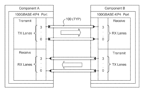
Figure 1 is a schematic diagram illustrating the structure of a 100GBASE-KP4
link, according to one embodiment;
Figure 2 is a diagram illustrating mapping for PAM4 encoding;
Figure 3 is a training state diagram for a 10GBASE-KR PHY;
Figure 4a is a block diagram showing the components of a training frame,
according to one embodiment;
Figure 4b is a schematic diagram illustrating a training frame and exemplary
signaling, according to one embodiment;
Figure 5a shows an exemplary structure for a Frame Marker and Coefficient
Update portion of a training frame, according to one embodiment;
Figure 5b shows an exemplary structure for a Status Report portion of a
training
frame, according to one embodiment;
Figure 6 is a diagram illustrating differential Manchester coding;
Figure 7 is a table illustrating exemplary encodings for cells in Coefficient
Update
fields;
Figure 8 is a table illustrating exemplary encodings for cells in Status
Report
fields;
Figure 9a is a schematic diagram illustrating the relationship between the
Data
Link and Physical layers of the OSI reference model and IEEE 802.3 LAN CSMA/CD
LAN model layers corresponding to the current draft of 100GBASE-KP4 defined in
IEEE
P802.3bj Draft 1.0;
Figure 9b is a schematic diagram illustrating further details of selected LAN
CSMA/CD layers in Figure 9a;
Figure 10 is a transmit adaption process diagram illustrating operations
performed
by the PMA sublayer during link up transmit operations.
-2-
CA 02908681 2015-10-02
WO 2013/191912 PCT/US2013/044369
Figure 10a is a transmit adaption process diagram illustrating operations
performed
by the PMA sublayer during transmission of the Frame Marker and Control
Channel
portions of a training frame; according to one embodiment;
Figure 10b is a transmit adaption process diagram illustrating operations
performed
by the PMA sublayer during transmission of the Training Pattern portion of a
training
frame; according to one embodiment;
Figure 11 is a receive adaption process diagram illustrating operations
performed
by the PMA sub-layer during link up receive operations.
Figure 11 a is a receive adaption process diagram illustrating operations
performed
by the PMA sublayer during receiving of the Frame Marker and Control Channel
portions
of a training frame; according to one embodiment;
Figure 1 lb is a transmit adaption process diagram illustrating operations
performed
by the PMA sublayer during receiving of the Training Pattern portion of a
training frame;
according to one embodiment;
Figures 12a and 12b are data structure diagrams illustrating the Frame Marker
and
Coefficient Update portions of a Training Frame, and further illustrating
respective parity
schemes, according to one embodiment;
Figure 13 is a diagram of a data structure illustrating a training frame,
accordingly
to one embodiment;
Figure 14 is a graph illustrating signaling corresponding to an simulation of
an
exemplary training frame;
Figure 15 is a diagram illustrating selection of four PRBS12 initiation states
selected from a possible 4095 initiation states;
Figure 16a is a frontal isometric view of an exemplary blade server chassis in
which a plurality of server blades are installed;
Figure 16b is a rear isometric view of the blade server chassis of Figure 16a;
Figure 16c is an isometric frontal view of an exemplary blade server rack in
which
a plurality of rack-mounted blade server chassis corresponding to Figures 16a
and 16b are
installed; and
Figure 17 shows details of the components of a typical server blade, according
to
one embodiment.
DETAILED DESCRIPTION
Embodiments of methods and apparatus for implementing training for a next-
generation high-speed Ethernet links are described herein. In the following
description,
-3-
CA 02908681 2015-10-02
WO 2013/191912 PCT/US2013/044369
numerous specific details are set forth (such as implementation of a 100Gbps
Ethernet
link) to provide a thorough understanding of embodiments of the invention. One
skilled in
the relevant art will recognize, however, that the invention can be practiced
without one or
more of the specific details, or with other methods, components, materials,
etc. In other
instances, well-known structures, materials, or operations are not shown or
described in
detail to avoid obscuring aspects of the invention.
Reference throughout this specification to "one embodiment" or "an embodiment"
means that a particular feature, structure, or characteristic described in
connection with the
embodiment is included in at least one embodiment of the present invention.
Thus, the
appearances of the phrases "in one embodiment" or "in an embodiment" in
various places
throughout this specification are not necessarily all referring to the same
embodiment.
Furthermore, the particular features, structures, or characteristics may be
combined in any
suitable manner in one or more embodiments.
Embodiments for facilitating link training for the high-speed Ethernet links
including the proposed 100GBASE-KP4 PHY are disclosed herein. In order to
preserve
compatibility with existing training mechanisms, some aspects of link training
for the
100GBASE-KP4 PHY are common to similar aspects defined for the IEEE 10GBASE-KR
PHY, which is targeted at 10Gbps links and is currently employed in various
types of
equipment such as switches and routers. Additionally, there are other common
aspects
that are defined in IEEE Std 802.3ap-2007. While these common aspects may be
identified
and briefly discussed herein, corresponding detailed discussions of how these
aspects may
operate or be implemented are generally not provided herein in order to not
obscure
inventive aspects of the embodiments. Other aspects of some embodiments are
described
in further detail in IEEE P802.3bj Draft 1.0 and IEEE P802.3bh Draft 3.1.
The Physical layer (also referred to a "PHY") structure of a 100GBASE-KP4 link
is illustrated in Figure 1. The PHY defines the physical structure of the
interconnect and is
responsible for dealing with details of operation of the signals on a
particular link between
two link partners, such as depicted by components A and B. This layer manages
data
transfer on the signal wires, including electrical levels, timing aspects, and
logical issues
involved in sending and receiving each bit of information across the parallel
lanes. As
shown in Figure 1, the physical connectivity of each interconnect link is made
up of four
differential pairs of signals 100, comprising lanes 0-3 in each direction.
Each port
supports a link pair consisting of two uni-directional links to complete the
connection
between two components. This supports traffic in both directions
simultaneously.
-4-
CA 02908681 2015-10-02
WO 2013/191912 PCT/US2013/044369
Components with 100GBASE-KP4 ports communicate using a pair of uni-
directional point-to-point links, defined as a link pair, as shown in Figure
1. Each port
comprises a Transmit (Tx) link interface and a Receive (Rx) link interface.
For the
illustrated example, Component A has a Tx port that is connected to Component
B Rx
port. One uni-directional link transmits from Component A to Component B, and
the other
link transmits from Component B to Component A. The "transmit" link and
"receive" link
is defined relative to which component port is transmitting and which is
receiving data. In
the configuration illustrated in Figure 1, the Component A transmit link
transmits data
from the Component A Tx port to the Component B Rx port. This same Component A
transmit link is the Port B receive link.
The 100GBASE-KP4 PHY uses a 4-level pulse amplitude modulation (referred to
as PAM4) signal to send and receive data across the channel. As shown in
Figure 2,
PAM4 consists of four logical levels that are mapped as follows:
0 maps to -1
1 maps to -1/3
2 maps to +1/3
3 maps to +1
Logical levels 0 and 3 respectively correspond to low and high level signals
having signal
levels -1 and +1, while logical levels 1 and 2 correspond to intermediate
level signals have
signal levels -1/3 and +1/3.
The physical signaling for the 100GBASE-KP4 PHY employs a Unit Interval (UI)
of 1 bit having a time corresponding to 13.59375 Gbd symbols (-73.6 psec). In
one
embodiment a Training Frame Word (TFW) of 46 UI is employed for link training.
In one embodiment, the format for the training sequence for the 100GBASE-KP4
PHY is loosely defined to be similar to that employed for the 10GBASE-KR PHY
defined
in the IEEE Std. 802.3ap-2007 specification. The training state diagram for
10GBASE-
KR PHY is shown in Figure 3. A significant difference between the 10GBASE-KR
PHY
and the 100GBASE-KP4 PHY is that the former defines a NRZ (Non-return to Zero)
2-
level (PAM2) PHY rather than a 4-level PAM4 signal.
The 100GBASE-KP4 link is established using the following sequence:
(1) Auto-negotiate capabilities to link partner
(2) Send out training sequence to tune PHY for the channel's characteristics
Obtain Frame Lock
TX FFE handshake: Adapt Tx coefficients to channel characteristics
-5-
CA 02908681 2015-10-02
WO 2013/191912 PCT/US2013/044369
DSP converged: Train Rx to channel
Status Exchange: Ready or not?
(3) Go to data mode and Send out idle symbols
The training frame is a fixed length structure that is sent continuously
during
training. As shown in Figure 4a, in one embodiment, a training frame 400
includes a
Frame Marker 402 comprising 1 TFW, a Control Channel including a Coefficient
Update 404 and a Status Report 406, each comprising 4 TFWs, and a Training
Pattern 408
comprising 182 TFWs for a total of 191 TFWs. Further details of training frame
400 are
shown in Figure 4b and discussed below.
In one embodiment, Frames are delimited by the bit pattern, hexadecimal
3FFFFFF800000 (23 ones followed by 23 zeros), as expressed in 13.59375 Gbd
symbols.
This is illustrated by the Frame Markers shown in Figures 4b, 5a, 5b, 12a,
12b, and 13 and
14. In one embodiment this may be changed to 0000007FFFFF (23 zeros followed
by 23
ones) if the total parity of the previous frame was odd. These patterns do not
appear in the
control channel or the training pattern and therefore serves as a unique
indicator of the
start of a training frame.
The control channel is transmitted using differential Manchester encoding DME.
An example of DME is shown in Figure 6. The rules of differential Manchester
encoding
are as follows:
a) A data transition shall occur at each cell boundary.
b) A mid-cell data transition shall be used to signal a logical one.
c) The absence of a mid-cell data transition shall be used to signal a logical
zero.
If a coding violation is detected within the bounds of the control channel in
a given
training frame, the contents of the control channel for that frame are
ignored.
As shown in Figures 4b, 5a and 5b, in one embodiment Coefficient Update 404
comprises a 16 cell request, while Status Report 406 comprises a 16 cell
Status. The
length for the cells in each of Coefficient Update 404 and Status Report 406
is 10 UI, and
each of the 4 TFWs are configured as four cells followed by a 6 UI overhead
field,
resulting in a control channel length of 8 x 46 = 368 UI. In one embodiment at
least a
portion of the cells in Coefficient Update 404 are mapped to corresponding
coefficient
update fields defined for the 10GBASE-KR PHY shown in Figure 7, while at least
a
portion of the cells in Status Report 406 are mapped to corresponding status
report fields
in defined for the 10GBASE-KR PHY shown in Figure 8.
-6-
CA 02908681 2015-10-02
WO 2013/191912 PCT/US2013/044369
Figure 9a shows details of the relationship between the Data Link and Physical
layers of the OSI reference model and IEEE 802.3 LAN CSMA/CD LAN model layers
corresponding to the current draft of 100GBASE-KP4 defined in IEEE P802.3bj
Draft 1Ø
Figure 9b shows further details of selected LAN CSMA/CD layers, including a
MAC
(Media Access Control) layer 900, a 100GBASE-R Physical Coding Sublayer (PCS)
sublayer 902, a Forward Error Correction (FEC) sublayer 904, a Physical Media
Attachment (PMA) sublayer 906, a Physical Media Dependent (PMD) sublayer 908,
and
an Auto-Negotiation (AN) sublayer 910. Data is received in digital format as a
binary bit
stream by MAC layer 900, which processes and forwards the binary data to
100GBASE-R
PCS sublayer 902, which applies digital rules to the binary data to transform
the data as
described below. The transformed digital data are then passed to FEC sublayer
904,
which performs Forward Error Correction. FEC uses the coding gain to increase
the link
budget and BER performance on a given channel. The link budget consists of the
electrical
parameters which define the connection between the transmit circuitry and the
receive
circuitry, such as insertion loss, return loss, pulse response, etc.
In the transmit direction, the role of PMA sublayer 906 is to adapt the signal
output
by FEC sublayer 904 to a PAM4 encoded signal to be passed to PMD sublayer 908
and
AN sublayer 910 for transfer over the attached medium. One embodiment of the
adaptation processes shown in Figure 10 includes an insert overhead block
1002, an insert
termination bits block 1004, a Gray coding block 1006, a [1/(1+D) mod 4]
precoding
block 1008, and a PAM4 encoding block 1010.
In further detail, incoming data 1000 in Figure 10 is received by PMA
sublayer 906 from FEC sublayer 904 comprising a PMA:IS UNITDATA i.request
(where i=0 to 3) primitive used to define the transfer of four streams of a
data from the
PMA client to PMA. The data conveyed by PMA:IS UNITDATA 0.request to
PMA:IS UNITDATA 3.request consists of four parallel streams of encoded bits,
one
stream for each of lanes 0-3. Each tx bit parameter is either a '1' or '0'.
The start
parameter is TRUE to indicate that the concurrent tx bit is the first bit of
the first, second,
third, or fourth FEC symbol in the FEC codeword, or is otherwise FALSE. On
each
transaction, tx-bit is assigned C(i, m, n), where i is the lane number, m is
an index
indicating the FEC codeword number and increments at the start of each
codeword, and n
is an index indicating the bit number within the codeword.
Insert overhead block 1002 creates a sequence of overhead frames by inserting
40
overhead bits for every 31280 FEC bits. The FEC bits, C(i, m, n) are mapped
into a
-7-
CA 02908681 2015-10-02
WO 2013/191912 PCT/US2013/044369
continuous sequence of overhead frames. The overhead frame is 31320 bits in
length.
Each bit in the overhead frame is denoted F(i, p, q), where: i is the lane
number; p is an
index that indicates the frame number and increments at the start of each
frame; and q is
an index that indicates the bit number within a frame with a range 1 to 31320.
The first 40
bits of the frame, F(i, p, 1) to F(i, p, 40) are the overhead bits. The next
31280 bits, F(i, p,
41) to F(i, p, 31320) are composed of the bits from 23 consecutive FEC
codewords.
The overhead bits are inserted in the frame as follows:
F(i, p, 1) = H(i, p, 1)
F(i, p, 2) = H(i, p, 2)
F(i, p, ...) = H(i, p, ...)
F(i, p, 40) = H(i, p, 40)
The FEC codeword bits are aligned such that F(i, p, 41) is the first bit of a
codeword, e.g., F(i, p, 41) = C(i, m, 1). The FEC bits are inserted into the
frame in the
order in which they were received from the FEC, e.g., F(i, p, 42) = C(i, m,
2), F(i, p, 43) =
C(i, m, 3), and so on.
Insert termination bits block 1004 creates a sequence of termination blocks by
inserting a termination bit for every 45 overhead frame bits. The termination
block is 46
bits in length. Each bit in a termination block is denoted T(i, r, s), where:
i is the lane
number; r is an index indicating block number and increments at the start of
each block;
and s is an index indicating the bit number within a termination block with a
range 1 to 46.
The first 45 bits of each termination block, T(i, r, 1) to T(i, r, 45), are
overhead frame bits.
The frame bits are aligned with the termination blocks such that the first bit
of an overhead
bit, F(i, p, 1), corresponds to the first bit of a termination block, T(i, r,
1). The 46th bit in
each termination block, T(i, r, 46), is set to zero. Overhead frame bits are
mapped to the
termination blocks in order of location within the overhead frame, e.g., T(i,
r, 2) = F(i, p,
2), T(i, r, 3) = F(i,p, 3), and so on.
The PMA sublayer next maps consecutive pairs of bits to one of four Gray-coded
via Gray coding block 1006. Each pair of bits, {A, 13}, of each termination
block are
converted to a Gray-coded symbol with one of the four Gray-coded levels as
follows:
{0, 0} maps to 0,
{0, 1} maps to 1,
{1, 1} maps to 2, and
{1,0} maps to 3.
-8-
CA 02908681 2015-10-02
WO 2013/191912 PCT/US2013/044369
Gray-coded symbols corresponding to each termination block are denoted G(i, r,
t), where: i is the lane number; r is an index indicating the termination
block number; and t
is an index indicating the symbol number within a termination block with a
range 1 to 23.
Pairing of bits is such that the first two bits of each termination block,
T(i, r, 1) and T(i, r,
2), form a pair. Each bit pair {T(i, r, 2t-1), T(i, r, 2t)} maps to {A, B} and
the Gray-coded
result is assigned to G(i, r, t). The gray-coded symbol G(i, r, 23) is formed
from the last
two bits of a termination block including one overhead frame bit and one
termination bit
(of value zero); thus G(i, r, 23), the Gray-coded termination symbol, always
takes the
value 0 or 3.
Precoding of the Gray-coded symbols is next performed by [1/(1+D) mod 4]
precoding block 1008. The precoder output symbols are denoted, P(i, r, t),
where: i is the
lane number; r is an index indicating the termination block number; and t is
an index
indicating the symbol number within a termination block with a range 1 to 23.
For each
Gray-coded symbol G(i, r, t), a precoded symbol, P(i, r, t) is determined by
the following
algorithm:
If t = 23 then
P(i, r, t) = G(i, r, t)
Else If t= 1 then
P(i, r, t) = (G(i, r, t) ¨ P(i, r-1, 23)) mod 4
Else
P(i, r, ,t) (G(i, r,t)¨ P(i, r, t-1)) mod 4
End If
The Gray-coded termination symbol, G(i, r, 23), is always equal to either 0 or
3.
The precoding algorithm above applies this symbol directly to the output, thus
re-
initializing the loop and ensuring that the precoded termination symbol, P(i,
r, 23), is
always either 0 or 3.
The last operation performed by PMA sublayer 906 is PAM4 encoding performed
by PAM4 encoding block 1010. The PAM4 encoded symbols are denoted Q(i, u),
where i
is the lane number and u is an index indicating the symbol number. Each
consecutive
precoder output symbol, P(i, rõt), is mapped to one of four PAM4 levels and
assigned to
the PAM4 encoder output Q(i, 32r+t). Mapping from the precoder output symbol
P(i, r,
,t) to a PAM4 encoded symbol Q(i, u) is shown in Figure 2 and discussed above.
The
termination symbols after PAM4 encoding, Q(i, 32r+32), are either ¨1 or +1.
-9-
CA 02908681 2015-10-02
WO 2013/191912 PCT/US2013/044369
In the received direction, the role of the 100GBASE-KP4 PMA is to adapt the
PAM4 encoded signal from the PMD to a FEC encoded signal to be passed to the
FEC for
further processing. One embodiment of the adaptation processes are shown in
Figure 11
and include a PAM4 decoding block 1100, a [(1+D) mod 4] coding block 1102, an
inverse
Gray coding block 1104, a remove termination bits block 1106, and a remove
overhead
block 1108. In general terms, each of these blocks performs an inverse
operation to a
corresponding block in Figure 10 described above. Accordingly, further details
are not
provided herein.
To simplify step (2) in the link establishment process discussed above when
TRANSMIT(TRAINING) as shown in Figure 3, the PAM4 multi-level signaling is not
used for the Frame Marker, Coefficient Update, and Status Report data. During
the
transmission of Frame Marker 402, Coefficient Update 404, and Status Report
406, the
PAM4 transmitter bypasses the overhead frame, termination block, gray coding,
and
1/(1+D) mod 4 precoding stages of the PMA transmit and receive functional
specifications. This is illustrated in Figure 10a, wherein data 1014 is
redirected by a
multiplexer (MUX) 1012 to PAM4 encoding block 1010, by passing each of insert
overhead block 1002, insert termination bits block 1004, Gray coding block
1006, and
[1/(1+D) mod 4] precoding block 1008. Therefore, the output levels are
restricted to level
-1 for a 0 and level +1 for a 1 to enable easy receiver lock to the training
pattern over poor
quality and non-equalized channels.
The corresponding receiver operations for processing received data during
transmission of Frame Marker 402, Coefficient Update 404, and Status Report
406 are
shown in Figure 1 1 a. As illustrated, a MUX 1112 is configured to output data
1114 from
PAM4 decoding block 1000, bypassing the operations of [(1+D) mod 4] coding
block 1102, inverse Gray coding block 1104, remove termination bits block
1106, and
remove overhead block 1108.
As discussed above, each TFW for the Coefficient Update 404 and Status
Report 406 includes a 6 UI overhead field comprising 6 overhead bits. In one
embodiment, the overhead bits are set to provide a DME logic value of '1',
e.g., coded as
000111 or 111000. This may be used to preserve DC balance for the TFW.
In one embodiment, a parity scheme is implemented through use of Coefficient
Update and Status Report fields. Under one implementation, cell 6 of the
coefficient
update field table of Figure 7 and status report field table of Figure 8 is
used to transmit
parity bits, as opposed to transmitting all O's defined for this cell by the
10GBASE-KR
-10-
CA 02908681 2015-10-02
WO 2013/191912 PCT/US2013/044369
PHY specification. Two parity bits are calculated for each field (Coefficient
Update and
Status Report) separately, such that each field as a whole, including the
parity bits, has
even parity. The parity is the number of logical-one cells in the field,
modulo 2 (not
including the overhead bits). Under this parity scheme a parity check may be
implemented to increase protection against false acceptance of sensitive
messages, e.g.,
preset, init, and receiver read. In one embodiment, if a parity violation is
detected within
the bounds of the respective field in a given training frame, the contents of
the control
channel for that frame shall be ignored.
Figures 12a and 12b show respective examples of parity schemes, according to
one
embodiment. In each case the resulting DME value for the 5:0 parity field is a
'1'. In
Figure 12a, a bit pattern of 111000 is used for the parity bits. In Figure
12b, a bit pattern
of 000111 is used for the parity bits.
In one embodiment, Training Pattern 408 uses the PMA transmit and receive
functional specifications as currently defined in IEEE P802.3bj Draft 1.0 to
enable the
transmitter and receiver to exercise termination block, gray coding, and
1/(1+D) mod 4
precoding stages, while the overhead framer is bypassed. Corresponding block
diagrams
to facilitate the transmitter and receiver operations are shown in Figures 10b
and 1 lb,
respectively. Training Pattern 408 employs all four levels of PAM4 signaling
to facilitate
receiver calibration.
In one embodiment, input data 1016 to the termination block logic (i.e.,
insert
termination bits block 1004 in Figure 10b) comprises a 12-bit Psuedo Random
Bit
Sequence known as PRBS12. PRBS12 is a 4095 bit sequence derived from the
function,
G(x) = 1 + x4 + X10 + X11 + X12
In one embodiment, each TFW comprises 45 bits of PRBS12 data plus one
termination bit. Two full sequences of PRBS12 data (8190 bits for PRBS12, 8372
bits
including the termination bits) are transmitted during the 182 TFWs
corresponding to
Training Pattern 408, as shown in Figures 4b and 13. In one embodiment, the
second
PRBS12 sequence comprises a bit inversion of the first, as depicted by PRBS12a
and
PRBS12b in Figure 4b.
In addition to the example training pattern shown in Figure 4b, Figure 14
shows an
example training pattern generated during a simulated link training operation.
Note the
full swing signaling on the left portion of the diagram during the Frame
Marker and
control channel portion of the frame. Also note the 4-level signaling on right
during the
training pattern portion of the frame.
-11-
CA 02908681 2015-10-02
WO 2013/191912 PCT/US2013/044369
In one embodiment, the training pattern initial states for lanes 0-3 are
derived in
the following manner. Out of 4095 possible initial states in PRBS12, there are
159 for
which the following process creates DC balanced results: Generate the full
PRBS12
starting from the initial state, and then another full PRBS12 from the same
state, inverted
and apply most of the PMA data encoding (block termination, gray coding,
1/(1+D) mod 4
precoding and PAM4 mapping) to the data. From these 159 states, four states
are selected
for which the output is DC balanced and final state of the precoder is '0'. In
one
embodiment, the initial four states are selected to be approximately 1/4-cycle
apart from
each other, as illustrated in Figure 15. An exemplary set of initial states
meeting the
foregoing conditions include (initial bits sent on the data path, LSB first):
S0=0x149,
S1=0x8C4, S2=0x00A, S3=OxA1C. For each physical lane i=0..3, the training
sequence
shall start from state Si. This will also uniquely identify the lanes if they
are swapped, and
save lane order identification later on. For this choice of initial PRBS
states, since the
initial precoder state is 0, the final state is also 0. This has the benefit
that the precoder
state is known to be 0 upon switching to data mode (i.e., run-time link
operation mode
after link initialization). PRBS state and precoder state shall not advance
during frame
marker and control channel transmission.
Exemplary Implementation Environment and Blade Server architecture
It is envisioned that aspects of the embodiments herein may be implemented in
various types of computing and networking equipment, such as switches, routers
and blade
servers such as those employed in a data center and/or server farm
environment.
Typically, the servers used in data centers and server farms comprise arrayed
server
configurations such as rack-based servers or blade servers.
These servers are
interconnected in communication via various network provisions, such as
partitioning sets
of servers into LANs with appropriate switching and routing facilities between
the LANs
to form a private Intranet. For example, cloud hosting facilities may
typically employ
large data centers with a multitude of servers.
As an overview, typical blade server components and systems are shown in
Figures
16a-c, and 17. Under a typical configuration, a rack-mounted chassis 1600 is
employed to
provide power and communication functions for a plurality of server blades
(i.e.,
blades) 1602, each of which occupies a corresponding slot. (It is noted that
all slots in a
chassis do not need to be occupied.) In turn, one or more chassis 1600 may be
installed in
a blade server rack 1603 shown in Figure 16c. Each blade is coupled to an
interface
plane 1604 (i.e., a backplane or mid-plane) upon installation via one or more
mating
-12-
CA 02908681 2015-10-02
WO 2013/191912 PCT/US2013/044369
connectors. Typically, the interface plane will include a plurality of
respective mating
connectors that provide power and communication signals to the blades. Under
current
practices, many interface planes provide "hot-swapping" functionality ¨ that
is, blades can
be added or removed ("hot-swapped") on the fly, without taking the entire
chassis down
through appropriate power and data signal buffering.
A typical mid-plane interface plane configuration is shown in Figures 16a and
16b.
The backside of interface plane 1604 is coupled to one or more power supplies
1606.
Oftentimes, the power supplies are redundant and hot-swappable, being coupled
to
appropriate power planes and conditioning circuitry to enable continued
operation in the
event of a power supply failure. In an optional configuration, an array of
power supplies
may be used to supply power to an entire rack of blades, wherein there is not
a one-to-one
power supply-to-chassis correspondence. A plurality of cooling fans 1608 are
employed
to draw air through the chassis to cool the server blades.
An important feature required of all blade servers is the ability to
communicate
externally with other IT infrastructure. This is typically facilitated via one
or more
network connect cards 1610, each of which is coupled to interface plane 1604.
Generally,
a network connect card may include a physical interface comprising a plurality
of network
port connections (e.g., RJ-45 ports), or may comprise a high-density connector
designed to
directly connect to a network device, such as a network switch, hub, or
router.
Blade servers usually provide some type of management interface for managing
operations of the individual blades. This may generally be facilitated by a
built-in network
or communication channel or channels. For example, one or more buses for
facilitating a
"private" or "management" network and appropriate switching may be built into
the
interface plane, or a private network may be implemented through closely-
coupled
network cabling and a network. Optionally, the switching and other management
functionality may be provided by a management switch card 1612 that is coupled
to the
backside or frontside of the interface plane. As yet another option, a
management or
configuration server may be employed to manage blade activities, wherein
communications are handled via standard computer networking infrastructure,
for
example, Ethernet.
With reference to Figure 17, further details of an exemplary blade 1700 are
shown.
As discussed above, each blade comprises a separate computing platform that is
configured to perform server-type functions, i.e., is a "server on a card."
Accordingly,
each blade includes components common to conventional servers, including a
main
-13-
CA 02908681 2015-10-02
WO 2013/191912 PCT/US2013/044369
printed circuit board (main board) 1701 providing internal wiring (i.e.,
buses) for coupling
appropriate integrated circuits (ICs) and other components mounted to the
board. These
components include one or more processors 1702 coupled to system memory 1704
(e.g.,
some form of Random Access Memory (RAM)), cache memory 1706 (e.g., SDRAM), and
a firmware storage device 1708 (e.g., flash memory). A NIC (network interface
controller) chip 1710 is provided for supporting conventional network
communication
functions, such as to support communication between a blade and external
network
infrastructure.
Other illustrated components include status LED (light-emitting
diodes) 1712, a set of RJ-45 console ports 1714 (only one of which is shown
for
simplicity), and a NIC 1715 coupled to an interface plane connector 1716.
Additional
components include various passive components (i.e., resistors, capacitors),
power
conditioning components, and peripheral device connectors.
Generally, each blade 1700 may also provide on-board storage. This is
typically
facilitated via one or more built-in disk controllers and corresponding
connectors to which
one or more disk drives 1718 are coupled. For example, typical disk
controllers include
SATA controllers, SCSI controllers, and the like. As an option, the disk
drives may be
housed separate from the blades in the same or a separate rack, such as might
be the case
when a network-attached storage (NAS) appliance or backend storage sub-system
that is
employed for storing large volumes of data.
NIC 1710 comprises circuitry and logic for facilitating corresponding
networking
operations, such as support for physical layer (L1) and data link layer
operations (L2).
Typically, upper layer operations are facilitated by an operating system
network stack that
would be hosted by an operating system running on processor 1702. However, in
some
embodiments, a NIC may employ its own network stack via embedded logic or the
like.
In a typical data center deployment, network switching elements comprise rack-
mounted equipment, such as would occupy a 1U, 2U, or 4U slot, or may be
implemented
via one or more server blades. Optionally, a network switching element may be
implemented use one or more server blades.
NIC 1715 comprises circuitry and logic for implementing high-speed
communication between multiple blades 1700 via interface plane 1604. In one
embodiment, NIC 1715 is configured to implement signaling and logic
corresponding to
the 100Gbps embodiments disclosed herein, including circuitry and logic for
implementing a 100GBASE-KP4 port and associated link training operations. To
further
facilitate inter-blade communication over the 100GBASE-KP4 PHY, interface
plane 1604
-14-
CA 02908681 2015-10-02
WO 2013/191912 PCT/US2013/044369
includes appropriate connectors, circuitry and wiring for facilitating the
physical media
aspect of the PHY (wiring not shown). For example, the circuitry may comprise
connectors and wiring for facilitating signaling over 8 differential pairs in
accordance with
the configuration shown in Figure 1.
In general, aspects of the link training embodiments disclosed herein may be
implemented hardware (via, e.g., embedded logic), or via a combination of
hardware and
software. For example, a network element may include a processor running a
software-
based network stack and associated logic implemented via software for
performing aspects
of the operations described herein. Optionally, similar logic could be
implemented via
embedded logic in a NIC, large-scale network interface, or the like.
In addition to implementation in a blade server, the principles and teachings
herein
may be implemented via other types of equipment, such as telecommunications
routers
and switches. For example, a typical telecom switch comprises a rack with
multiple cards
coupled to a backplane, wherein the cards are generally analogous to the
blades and the
backplane is analogous to the interface plane in a blade server. Accordingly,
the cards
would be configured with circuitry and logic for implemented 100GBASE-KP4
ports, and
the backplane would include connectors, circuitry, and wiring for facilitating
the physical
media aspect of the 100GBASE-KP4 PHY.
Although some embodiments have been described in reference to particular
implementations, other implementations are possible according to some
embodiments.
Additionally, the arrangement and/or order of elements or other features
illustrated in the
drawings and/or described herein need not be arranged in the particular way
illustrated and
described. Many other arrangements are possible according to some embodiments.
In each system shown in a figure, the elements in some cases may each have a
same reference number or a different reference number to suggest that the
elements
represented could be different and/or similar. However, an element may be
flexible
enough to have different implementations and work with some or all of the
systems shown
or described herein. The various elements shown in the figures may be the same
or
different. Which one is referred to as a first element and which is called a
second element
is arbitrary.
In the description and claims, the terms "coupled" and "connected," along with
their derivatives, may be used. It should be understood that these terms are
not intended as
synonyms for each other. Rather, in particular embodiments, "connected" may be
used to
indicate that two or more elements are in direct physical or electrical
contact with each
-15-
CA 02908681 2015-10-02
WO 2013/191912 PCT/US2013/044369
other. "Coupled" may mean that two or more elements are in direct physical or
electrical
contact. However, "coupled" may also mean that two or more elements are not in
direct
contact with each other, but yet still co-operate or interact with each other.
An algorithm is here, and generally, considered to be a self-consistent
sequence of
acts or operations leading to a desired result. These include physical
manipulations of
physical quantities. Usually, though not necessarily, these quantities take
the form of
electrical or magnetic signals capable of being stored, transferred, combined,
compared,
and otherwise manipulated. It has proven convenient at times, principally for
reasons of
common usage, to refer to these signals as bits, values, elements, symbols,
characters,
terms, numbers or the like. It should be understood, however, that all of
these and similar
terms are to be associated with the appropriate physical quantities and are
merely
convenient labels applied to these quantities.
An embodiment is an implementation or example of the inventions. Reference in
the specification to "an embodiment," "one embodiment," "some embodiments," or
"other
embodiments" means that a particular feature, structure, or characteristic
described in
connection with the embodiments is included in at least some embodiments, but
not
necessarily all embodiments, of the inventions. The various appearances "an
embodiment," "one embodiment," or "some embodiments" are not necessarily all
referring
to the same embodiments.
Not all components, features, structures, characteristics, etc. described and
illustrated herein need be included in a particular embodiment or embodiments.
If the
specification states a component, feature, structure, or characteristic "may",
"might", "can"
or "could" be included, for example, that particular component, feature,
structure, or
characteristic is not required to be included. If the specification or claim
refers to "a" or
"an" element, that does not mean there is only one of the element. If the
specification or
claims refer to "an additional" element, that does not preclude there being
more than one
of the additional element.
The above description of illustrated embodiments of the invention, including
what
is described in the Abstract, is not intended to be exhaustive or to limit the
invention to the
precise forms disclosed. While specific embodiments of, and examples for, the
invention
are described herein for illustrative purposes, various equivalent
modifications are possible
within the scope of the invention, as those skilled in the relevant art will
recognize.
These modifications can be made to the invention in light of the above
detailed
description. The terms used in the following claims should not be construed to
limit the
-16-
CA 02908681 2015-10-02
WO 2013/191912 PCT/US2013/044369
invention to the specific embodiments disclosed in the specification and the
drawings.
Rather, the scope of the invention is to be determined entirely by the
following claims,
which are to be construed in accordance with established doctrines of claim
interpretation.
-17-