Note: Descriptions are shown in the official language in which they were submitted.
CA 02908798 2015-10-05
,
Hydraulic Brake System
Description
The invention relates to a brake system for a passenger transportation system
which is
embodied as an elevator, escalator, or moving walk, a corresponding passenger
transportation system, and a method for controlling the braking force in such
a passenger
transportation system. The invention especially relates to the field of
elevator systems.
From EP 0 648 703 Al a braking safety device for an elevator car is known.
Therein, a
braking device is provided which grips on a guiderail, the braking force that
is exerted by
the braking device on the guiderail being regulated by a regulating device.
The braking
device embraces a free web of the guiderail, which is provided with running
surfaces,
there being provided for each running surface a braking plate which is borne
by a
braking-plate holder. Further, at least one of the braking plates is
actuatable by means of a
brake cylinder, the brake cylinder being pressurizable with a regulated
pressure which is
generated in a pressurizing medium by means of a pressurizing device and
regulated by
means of the regulating device. The pressurizing device that belongs to the
safety device
has a pressure pump, which is driven by a motor, which pumps pressurizing
medium
from a tank through a non-return valve to a pressure accumulator, until the
maximum
accumulated pressure that is set on a second pressure switch is attained. If
the
accumulated pressure falls below a minimum pressure that is settable on a
first pressure
switch, the pressure accumulator is reloaded to the maximum accumulated
pressure. The
accumulated pressure is greater than the braking pressure that is required in
the event of a
braking. In the event of a braking, a 3/2-way valve and a pressure-regulating
valve
pressurize the brake cylinder with the pressurizing medium that is conveyed
through the
pressurizing-medium pipeline. After the braking event, the 3/2-way valve and
the
pressure-regulating valve return to their starting state, so that the
pressurizing medium in
the brake cylinder can depressurize through a settable throttle valve to a
tank. By this
means it is possible that the deceleration of the elevator car remains
constant and
maintains a predefined value during the entire braking operation. For this
purpose, the
regulating device compares the predefined value, for example the acceleration
due to
gravity (1 g), with the value that is measured on the elevator car by means of
a
deceleration sensor and compensates differences between the two values by
means of a
CA 02908798 2015-10-05
- 2 -
greater or lesser pressurization of the brake cylinder by means of the
pressure regulating
valve. As soon as the elevator car has come to a standstill, the regulating
device changes
the setting of the pressure regulating valve in such manner that the braking
force of the
braking cylinder attains its maximum value. The elevator car is thereby
blocked in the
elevator hoistway. In a further possible embodiment, which is known from EP 0
648 703
Al, in the hydraulically pressureless state a compression spring presses the
brake plates
against the running surfaces of the guiderail. By this means, the elevator car
is held with
maximum braking force on the guiderails. To establish and maintain the
operational
readiness of the pressurizing device, based on the signals of the first
pressure switch and
of the second pressure switch, the regulating device that is connected with
the elevator
control switches the motor on and off If the accumulated pressure in the
pressure
accumulator falls below a minimum pressure, which is settable on the first
pressure
switch, in response to the pressure-switch signal the regulating device
switches the motor
on. The motor remains switched on until the maximum pressure at the second
pressure
switch is attained. If the regulating device switches a 2/2-way valve on,
pressuring agent
flows into the cylinder space, as a result of which the compression spring is
compressed.
Upon attainment of a maximum braking pressure, the regulating device closes
the 2/2-
way valve. In this operating state of the pressurizing device, the brake
plates are raised
from the running surfaces of the guiderail. By increasing and decreasing the
braking force
of the braking-force cylinder, the deceleration of the elevator car can be
held constant,
maintaining a predefined value during the entire braking operation.
The braking safety device for an elevator car which is known from EP 0 648 703
Al has
the disadvantage that the actuation of the braking device and the regulation
of the braking
force are elaborate. In particular, the use of the pressure accumulator and of
the regulating
valve are costly and elaborate. Additionally necessary for a reliable
regulation operation
is that the pressure in the pressure accumulator is set and maintained within
a pressure
range that is as narrow as possible, which calls for a frequent switching on
and off of the
motor and of the pump as well as precisely operating switching elements and
correspondingly frequent maintenance. Further, in the operating mode in which
the brake
is closed via the pressure in the pressure accumulator, the use of components
of the
hydraulic system that are as leakproof as possible is necessary, since
otherwise the energy
consumption for the regular replenishment of the pressure agent, and for the
maintenance
of the braking pressure, is too great for economical operation. However, also
in the
CA 02908798 2015-10-05
,
- 3 -
operating mode in which the braking force is reduced through the pressure of
the
pressurizing device, the problem arises that, in order to ensure the
operational readiness,
the pressure of the pressurizing device must be constantly maintained, which
results in a
high energy requirement. In particular as a consequence of the large number of
components and elements of the hydraulic system that are required, leakage
losses occur,
and hence a correspondingly high energy consumption and a high maintenance
requirement.
Known from EP 1 657 204 A2 are various embodiments for guided lifting systems
with
holding devices and safety gears, wherein a car can be guided on a guiderail
in traveling
manner.
The object of the invention is to provide a brake system for a passenger
transportation
system, a passenger transportation system, and a method for controlling the
braking force
in such a passenger transportation system, which is of simple construction,
with good
regulability, and with an overall low energy consumption.
In what follows, solutions and proposals for a corresponding brake system, for
a
passenger transportation system, and a method, are presented, which solve at
least parts
of the set objective. In addition, advantageous augmentary or alternative
further
developments and embodiments are presented.
Preferably, the passenger transportation system is embodied as an elevator.
The brake
system serves to halt an elevator car of the elevator. In corresponding
manner, however, a
halting of a respective passenger transportation system by the brake system
can also take
place in the case of an escalator or a moving walk. The explanations that have
been given
in relation to the elevator and the elevator car therefore also apply in
corresponding
manner for an escalator or a moving walk. Although the present explanations
generally
refer to passenger transportation systems, the explanations can self-evidently
also be
applied to systems for the transportation of freight or goods. This applies
particularly to
freight elevators or goods lifts.
The brake system is embodied so that a return-flow volume stream is permitted
in such
manner that a pressure in the piston chamber of an actuating device arises
that
CA 02908798 2015-10-05
v
- 4 -
corresponds to an equilibrium. The equilibrium corresponds to a state in which
a
discharge volume stream is identical to the return-flow volume stream. In
operation, for
example when setting a desired braking force, in the event of a variation of
the return-
flow volume stream a corresponding change of pressure in the direction of the
respective
resulting equilibrium can occur, which represents a quasi-static case.
Practically, an at
least asymptotic approximation to the resulting equilibrium takes place. By
this means,
particularly in a switchover operation, changes of the discharge volume stream
as well as
of the return-flow volume stream occur, so that the pressure that arises in
the piston
chamber can also only occur after a short adaptation time. If necessary,
however, through
suitable control operations, especially regulating operations, a control
device can shorten
such adaptation times. Furthermore, through a suitable embodiment of the
components,
the necessary adaptation time for the controlling or regulating operations can
be
predefined, or set, sufficiently short.
The control device is further so embodied as to set the pressure in the piston
chamber of
the actuating device at least indirectly via at least the discharge volume
stream of the
pump. Hence, in a corresponding embodiment, the control device can
additionally set the
discharge volume stream of the pump in another manner, in particular by a
variation of
the return-flow volume stream.
It is advantageous for the control device at least indirectly to switch a
motor that drives
the pump in such manner that the discharge volume stream of the pump is
predefined by a
predefined rotational speed of the pump and/or by a predefined power of the
motor that is
predefined by the control device. Alternatively or augmentarily, the control
device can
switch the motor at least indirectly in such manner that a predefined motor
current of the
motor is set, whereby a discharge volume stream that corresponds to the motor
current is
set. In particular if the pump is embodied as a volume pump, especially as a
gear pump,
the discharge volume stream of the pump can in advantageous manner be set at
least
approximately via the rotational speed of the pump or the power of the motor.
Through a
fixed coupling of the rotational speed of the motor with the rotational speed
of the pump,
which can take place via a common axle or via a gearbox, through the switching
of the
motor with a certain rotational speed, the discharge volume stream of the pump
can be
set. The discharge volume stream of the pump can thus be varied and set in
simple
manner.
CA 02908798 2015-10-05
- 5 -
Also advantageous is for the control device to switch the motor by means of a
frequency
converter. By this means, an indirect switching of the motor by the control
device is
possible, in particular it being possible for the rotational speed of the
motor to be
predefined.
Also advantageous is for a throttle to be provided and for the throttle to be
connected at
one side at least indirectly with the at least one piston chamber of the
actuating device
and/or at least indirectly with a discharge side of the pump. Further
advantageous is for
the throttle at the other side to be connected at least indirectly with a tank
out of which
the pump pumps and/or at least indirectly with a suction side of the pump.
Through the
throttle, the return-flow volume stream is thereby permitted. Depending on the
embodiment of the brake system, the throttle can also serve to additionally
raise the
return-flow volume stream to a system-dependent leakage. It is therefore
advantageous
for the return-flow volume stream to be at least partially permitted via the
throttle.
Further in advantageous manner at least a filter is provided which cleans the
brake fluid,
in particular an oil, in order to filter soiling and thereby assure a long
service life of the
brake system. In particular, it is advantageous for the throttle to be
connected at one side
by means of the filter with the piston chamber of the actuating device and/or
by means of
the filter with the discharge side of the pump. In addition, or alternatively,
it is further
advantageous for the throttle at the other side to be connected by means of a
filter with
the tank and/or by means of a filter with the suction side of the pump. If the
filter is
arranged, for example, between the tank and the suction side of the pump, a
soiled filter
does not then hinder the return-flow volume stream. By this means, a related
influencing
of switching of the braking device can be avoided.
Further advantageous is for the throttle to be embodied in such manner that
the return-
flow volume stream that is permitted by the throttle, or the part of the
return-flow volume
stream that is permitted by the throttle, increases at least approximately
linearly with the
pressure in the piston chamber. For this purpose, it is particularly
advantageous for the
throttle to have an orifice plate or to be embodied at least essentially by an
orifice plate.
Such an orifice plate can have a fixed aperture cross-section. By this means,
a volume
stream that is permitted by the throttle is at least approximately
proportional to the
CA 02908798 2015-10-05
. '
- 6 -
pressure in the piston chamber. The term "throttle" is, however, to be
understood
generally and also includes other embodiments and is not restricted to orifice
plates or
constrictions.
Also advantageous is for the throttle to be embodied as a settable throttle.
In this case, in
a possible embodiment, the settable throttle can be set by an authorized
person. This can
take place, for example, during an installation or mounting of the brake
system and, if
necessary, be subsequently changed by the authorized person. By this means, an
adaptation to the respective application case, and a matching in relation to
tolerances, or
in relation to the differences in switching behavior that arise from the
concrete application
case, is possible. The settable throttle can, however, also be embodied to be
switchable by
the control device of the brake system, in order to vary the throttling action
of the throttle
within the framework of the control. Such a switchable throttle enables
control concepts
in which the control device sets the pressure in the piston chamber of the
actuating device
at least indirectly via the discharge volume stream of the pump as well as the
return-flow
volume stream, which is settable by the switchable throttle.
Further advantageous is for the pump to be embodied as a pump with a self-
leakage and
for the return-flow volume stream to be at least partly enabled via the self-
leakage of the
pump. If the self-leakage of the pump is sufficiently large, a throttle to
permit the return-
flow volume stream can also be obviated. In particular, an inexpensive pump
can be
selected, which permits a certain leakage and hence a certain part of the
return-flow
volume stream. Via the throttle, in particular a settable throttle, the return-
flow volume
stream can be increased in a desired manner. This results, both in relation to
the self-
leakage of the pump and to the throttling effect of the throttle, in a desired
dependence of
the return-flow volume stream on the pressure in the piston chamber of the
actuating
device.
Preferably, the control device is connected with a sensor, which registers at
least a
measurement parameter of the brake fluid or of the actuating device. The
control device
can correspondingly set the discharge volume stream of the pump to set the
pressure in
the piston chamber of the actuating device taking into account this
measurement
parameter. By this means, parameters that affect the brake system can be
considered or
compensated.
CA 02908798 2015-10-05
- 7 -
Preferably, for example, a sensor in the form of a temperature sensor is used
which
registers a temperature of the brake fluid. By this means, the control device
can at least
indirectly set the pressure in the piston chamber of the actuating device at
least indirectly,
or at least set the discharge volume stream of the pump taking into account
the registered
temperature of the brake fluid. The temperature of the brake fluid can
therefore be taken
into account by the control. In particular, a temperature compensation can
thus be
realized.
In addition, or alternatively, it is advantageous for the control device to be
connected with
a sensor in the embodiment of a pressure sensor, which registers the pressure
in the piston
chamber of the actuating device. By this means, the control device can at
least indirectly
set the pressure in the piston chamber of the actuating device via the
discharge volume
stream of the pump, taking into account at least the registered pressure in
the piston
chamber of the actuating device. In this manner, a regulation can also be
realized, in
which, for example, the rotational speed of the pump can be suitably increased
or
decreased. However, the registered pressure in the piston chamber can also be
used as one
of several measurement parameters in order to adapt the braking behavior of
the braking
device over several switching cycles. By this means, a self-regulation is
attainable, in
which, for example, soiling of a filter, or changes of the return-flow volume
stream that
are made necessary through changes of the leakage, or through the ambient
temperature,
and suchlike, can be compensated in simple manner. In particular, a
compensation of
changes that occur in the course of time can take place independent of the
concrete cause.
Further advantageous is for the control device to be connected with a sensor
in the
embodiment of a force sensor, which registers an activating force of the
activating device
which is dependent on the pressure in the piston chamber. By this means, the
control
device can at least indirectly, via the discharge volume stream of the pump,
taking into
account at least the registered actuating force of the actuating device, set
the pressure in
the piston chamber of the actuating device. Also by this means, a regulation
can be
realized, in which the actuating force is set to a desired target value.
Further,
corresponding to the registration of the pressure in the piston chamber of the
actuating
device, a compensation of deviations that occur over the operating life can be
achieved
also through the registered actuating force. By this means, the control can be
improved.
CA 02908798 2015-10-05
- 8 -
Also advantageous is for the control device to be connected with a sensor in
the
embodiment of a distance sensor, which registers relative to a piston bore, or
variable
height of the piston chamber, a displacement distance of an adjustable piston
of the
actuating device that bounds the piston chamber. Via the registered
displacement
distance, or the registered height of the piston chamber, an improvement of
the control
and a regulation of the pressure in the piston chamber that takes into account
the
displacement distance can be achieved. In particular, via the registered
height, a feeding
or displacement movement of the piston can rapidly take place and be
controlled.
Further, for reasons of redundancy, a plurality of measurement parameters can
be
registered and taken into account in the control. The accuracy of the control
can thereby
be improved and the operating safety be increased.
Further advantageous is for the braking device to be embodied as a
hydraulically opened
braking device. Hereby, the braking force can be supplied by a spring element
or similar,
while the pressure in the piston chamber is sufficiently low. Hence, the pump
need only
be switched on when the braking device is open, in other words, when it does
not need to
brake. In particular in an elevator, as a rule, the elevator car spends most
of its time in a
halted, or waiting, position. A switched-on time, during which the braking
device releases
the elevator car, is therefore comparatively small, particularly, in many
cases,
substantially less than 50 %, and in relation to the switched-on time of the
elevator
system, substantially less than 50%. In view of the energy consumption, it is
therefore
expedient to use the pressure in the piston chamber of the actuating device,
which is
produced by the driving of the pump, to release the braking device, in other
words, as
explained above, to embody the braking device as a hydraulically opened
braking device.
Also advantageous is for a pressure-relief device to be provided, which, in
the event of an
actuation, rapidly reduces the pressure in the piston chamber, and for the
control device to
be so embodied as to actuate the pressure-release device in a rapid-braking
operating
mode. Hence, with an opened braking device, in particular an emergency stop
can be
realized through the pressure-release being actuated in the rapid-braking
operating mode.
This results in a rapid reduction, or even collapse, of the pressure in the
piston chamber of
the actuating device and hence to an immediate triggering of the braking
device.
CA 02908798 2015-10-05
- 9 -
It is also advantageous for a pressure-limiting device to be provided, which
limits the
pressure in the piston chamber. In the case of an opened braking device, the
pressure in
the piston chamber can thereby be limited to a pressure that is sufficient to
reliably open
the braking device. In a hydraulically actuated braking device, the maximum
possible
braking force can be set by the pressure-limiting device. The system is also
protected
against an overloading, for example on account of blocked pipelines.
In advantageous manner, the pump is embodied as a volume pump. In particular
by this
means, via a rotational-speed reduction, the desired pressure in the piston
chamber can be
set. For this purpose, the pump can be embodied as a piston pump or,
advantageously, as
a gear pump.
For reasons of redundancy, also a plurality of braking devices, a plurality of
pumps, and a
plurality of control devices can be provided, there being assigned to each
braking device a
pump and a control device. By this means, on the one had an improved switching
of each
braking device is possible, since in each case the braking force can be set
individually. In
particular by this means, differences between the braking forces of the
individual braking
devices can be avoided. In addition, the operating safety is thereby
increased.
Preferred exemplary embodiments of the invention are explained in greater
detail in the
description that follows below by reference to the attached drawings. Shown
are in
Fig. 1 a schematic representation of a passenger transportation system, in
particular of an
elevator with a brake system;
Fig. 2 a brake system in a partial, schematic representation corresponding to
an
exemplary embodiment of the invention; and
Fig. 3 a diagram explaining the manner of functioning of the brake system.
Fig. 1 shows a passenger transportation system 1, which is embodied as an
elevator
(elevator system) 1, with a brake system 2. In a correspondingly modified
embodiment,
the passenger transportation system 1 can also be embodied as an escalator or
moving
CA 02908798 2015-10-05
-
walk.
The passenger transportation system 1 has an elevator car 33. The elevator car
33 is
suitable for accommodating passengers or goods. In the example, the elevator
car 33 is
connected by means of suspension means 36 via a drive 37 to a counterweight
35. The
5 elevator car 33 is guided by guide shoes 34 on guiderails 3. The
guiderail 3 comprises a
rail foot and a guiding and braking web 4. The rail foot of the guiderail 3
can, for
example, in an elevator hoistway of the elevator I be joined with a wall of
the elevator
hoistway or with a suitable supporting structure. By this means, the brake
system 2 is
assigned to the braking web 4 of the guiderail 3. As a rule, in such a
passenger
10 transportation system 1, a pair of guiderails 3 is used, one guiderail
respectively being
arranged on each side of the elevator car. Correspondingly, arranged in the
elevator car
33 are two brake systems 2, each of which is assigned to one of the
guiderails. Further
brake systems can also be provided, which are also assigned to the braking web
4 and/or
to at least one further braking web. Hence, the elevator 1 has at least one
brake system 2.
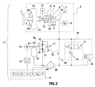
Fig. 2 shows a brake system 2 which can be used, for example, for the elevator
that is
described above. The brake system 2 has a braking device 5 with a housing 6
and an
actuating device 7, wherein the actuating device 7 has a piston 8 which is
guided in a
piston bore 9 of the housing 6. In the piston bore 9, an end-face 10 of the
piston 8 bounds
a piston chamber 11, whereby the volume of the piston chamber 11 depends on a
displacement distance d of the piston 8 in the piston bore 9. The displacement
distance d
thus matches a height d of the piston chamber 11. The volume of the piston
chamber 11 is
thus proportional to the displacement distance d, or the height d, of the
piston chamber
11.
The piston bore 9 is preferably embodied cylindrically as a cylinder bore in
which the
displaceable piston 8 is movable. Hence, the displacement of the piston 8
relative to the
piston bore 9 is relevant. In the event of a displacement, either the piston 8
or the piston
bore 9 can be arranged locationally fixed. Also an arrangement in which both
the piston 8
and the piston bore 9 can move is possible.
In addition, the braking device 5 has a spring element 12. The spring element
12
counteracts an enlargement of the volume of the piston chamber 11 and hence an
enlargement of the height d. In operation, in the piston chamber 11 is a brake
fluid that is
. CA 02908798 2015-10-05
- 11 -
under a pressure pB. Hence, the force of the spring element 12 acts against
the pressure pB
in the piston chamber 11.
Provided in this exemplary embodiment is a pressure sensor 13, which measures
the
pressure pB in the piston chamber 11. Also provided is a control device 14
which in
suitable manner is connected with the pressure sensor 13.
The brake system 2 further has a motor 15 and a pump 16 with changeable
direction of
rotation, or changeable direction of pumping, or at least with a changeable
discharge
volume stream Qp. The pump 16 can have a self-leakage 17, which in Fig. 2 is
shown as a
throttled auxiliary pipeline. However, in a modified embodiment, the pump 16
can also
be embodied as at least essentially leakage-free. The pump 16 is preferably
embodied as a
volume pump, particularly as a gear pump. The pump 16 is driven by the motor
15 via a
common axle 18. In a modified embodiment, the pump 16 can also be driven by
the
motor 15 through a gearbox.
At least indirectly, the control device 14 switches the motor. In this
exemplary
embodiment, the control device 14 controls the motor 15 by means of a
frequency
converter 19. Further, the brake system 2 has a tank 20, from which the pump
16 pumps
the brake fluid into the piston chamber 11. The tank 20 is connected with a
suction side
21 of the pump 16. The piston chamber 11 is connected with a discharge side 22
of the
pump 16.
Also provided is a throttle 25, which at one end is connected with the piston
chamber 11
of the actuating device 7 and with the discharge side 22 of the pump 16. At
its other end,
the throttle 25 is connected via a filter 26 with the suction side 21 of the
pump 16 and
with the tank 20, out of which the pump 16 pumps. Hence, the filter 26 is
connected at
one end with the throttle 25 and at the other end both with the tank 20 and
with the
suction side 21 of the pump 16.
In this exemplary embodiment, the throttle 25 is embodied at least essentially
by an
orifice plate. Depending on the pressure pB in the piston chamber 11, a return-
flow
volume stream QL arises. In this exemplary embodiment, this return-flow volume
stream
QL divides itself between the self-leakage 17 and the throttle 25. Further,
depending on a
rotational speed n of the pump 16, the discharge volume stream Qp of the pump
16
CA 02908798 2015-10-05
I µ ,
,
- 12 -
results. In this respect, the rotational speed n can be predefined by the
control device 14.
However, the rotational speed n of the pump 16 can also result in relation to
a predefined
power P of the motor 15 or its motor current I, wherein the power P or the
motor current I
can be varied by the control device 14.
There follows a more detailed explanation of the embodiment and manner of
functioning
of the brake system 2 by reference to Fig. 3.
Fig. 3 shows a diagram which explains the manner of functioning of the brake
system 2
of Fig. 2. Shown there on the abscissa is a pressure p. Shown on the ordinate
is a volume
stream Q. Shown in the diagram are three curves QL, - 0
Ono QPn`= Shown for the return-flow
volume stream QL is a linear dependency on the pressure p. The return-flow
volume
stream QL that occurs via the self-leakage 17 and the throttle 25 is therefore
proportional
to the pressure p. Further, at constant rotational speed n, with increasing
pressure p, the
discharge volume stream Qp decreases. Therefore, in the diagram, two curves
with
discharge volume streams Qp, Qpn, are shown, a first curve representing a
discharge
volume stream Qp, at a first rotational speed n and a second curve
representing a
discharge volume stream Qpn, at a second rotational speed n'. The rotational
speed n' is
greater than the rotational speed n of the pump.
In quasi-static equilibrium, the return-flow volume stream QL is always ¨
depending on
the rotational speed n ¨ equal to the discharge volume stream Qpn, Qp.. Hence,
in the
piston chamber 11 of the actuating device 7, the pressure n
,13n,, i- n
Bn` that corresponds to the
rotational speed n, n' arises, as is depicted in Fig. 3. Hence, the
equilibrium is a stable
equilibrium. If, for example, in equilibrium, the pressure p were less than
the pressure pa,
this would initially result in a smaller return-flow volume stream QL than the
discharge
volume stream Qp. This means, however, that more brake fluid is pumped into
the piston
chamber 11 than flows out of it. This results in a pressure increase in the
piston chamber
11, as well as in an increase in the volume of the piston chamber 11, which
results in an
increase in the displacement distance d or in the height d. Taking into
account the spring
force of the spring element 12 that hereby also increases, an increase in the
pressure in the
piston chamber 11 continues until the pressure pB is attained which is shown
in Fig. 2.
It should be noted that the dependency of the discharge volume stream Qp on
the pressure
p in the piston chamber 11 always applies for a certain rotational speed n or
a certain
CA 02908798 2015-10-05
=
- 13 -
power P or a certain motor current I. In the event of a change of the
rotational speed n of
the pump 16, or of the power P, or of the motor current I, of the motor 15,
there results
another association which can be at least approximately described by a
displacement of
the entire curve in a direction 27 or opposite to the direction 27. Therein, a
displacement
of the curve Qp in the direction 27 is achieved through an increase of the
rotational speed
n or an increase of the power P or of the motor current I. Correspondingly, a
reduction of
the rotational speed n or a reduction of the power P or of the motor current I
results in a
displacement opposite to the direction 27. In Fig. 3, for example, discharge
volume
streams Qpn, Qpw at two different rotational speeds n, n' are shown. Self-
evidently, in a
rotational-speed regulated pump, there is an array of discharge volume
streams, wherein
for each rotational speed n there is an associated equilibrium-point discharge
volume
stream Qp that equals the return-flow volume stream QL.
To change the pressure pB in the piston chamber 11, the control device 14
changes the
rotational speed n, the power P, or the motor current I. Through the change in
the entire
curve Qp that is brought about in this manner, a new equilibrium results, in
which the
return-flow volume stream QL is equal to the discharge volume stream Qp, which
corresponds to a changed intersection between the curves QL, Qp. Hence, in
equilibrium,
a new pressure pB arises in the piston chamber 11.
Hence, the control device 14 can set the pressure pB in the piston chamber 11
of the
actuating device 7 via the discharge volume stream Qp or via the rotational
speed n of the
pump 16. In a modified embodiment, the throttle 25 can be embodied as a
settable throttle
25, whereby a stability is enabled by the control device 14. The control
device 14 can
then additionally set the pressure pB also via the return-flow volume stream
QL. Since,
through a change in the throttle action of the throttle 25, in particular of
an aperture cross-
section of the orifice plate 25, the gradient of the curve QL can be varied.
For an
inexpensive and simple embodiment of the brake system 2, it is, however, also
advantageous for the control device 14 to set the pressure pB in the piston
chamber 11 of
the actuating device 7 at least indirectly via only the discharge volume
stream Qp of the
pump 16.
Depending on the pressure pB in the piston chamber 11, a displacement of the
actuating
device 7 takes place. The actuating device 7 acts on brake shoes 28, 29 of the
braking
CA 02908798 2015-10-05
- 14 -
device 5 as indicated by the double arrows 23, 24 in Fig. 2. Hence, the
braking device 5
can be embodied as a hydraulically actuated or hydraulically opened braking
device 5. In
an embodiment as a hydraulically actuated braking device 5, an increase in
pressure of
the pressure pB in the piston chamber 11 results initially in a laying of the
brake shoes 28,
29 against the brake rail 4 and then in an increase of the braking force. In
an embodiment
as a hydraulically opened braking device 5, the maximum braking force of the
spring
element 12 is attained and, by means of an increasing pressure pB in the
piston chamber
11, is gradually reduced.
Also in this exemplary embodiment, a temperature sensor 30 is provided, which
is
arranged in the return flow after the filter 26. Via the temperature sensor
30, a
temperature T of the brake fluid is registered. The temperature sensor 30 can
also be
situated at a different point. The control device 14 is connected with the
temperature
sensor 30. Further provided is a force sensor 31, which registers an actuating
force F of
the actuating device 7 which is registered by the pressure pB in the piston
chamber 11.
The pressure sensor 31 is connected in suitable manner with the control device
14.
Further provided is a distance sensor 32 which registers the displacement
distance d of
the piston 8 or the height d of the piston chamber 11. The distance sensor 32
is connected
in suitable manner with the control device 14.
When switching the pump 16, the control device 14 can take account of the
registered
measurement parameters of the sensors, namely the displacement distance d, the
temperature T, the pressure pB and the force F. Depending on the embodiment,
one or
more of these parameters d, T, pB, F can be used, whereby sensors 13, 30, 31,
32 that are
not required can also be obviated. Also possible in a particularly simple
embodiment of
the brake system 2 is a control, which is independent of such registered
parameters d, T,
pB, F, so that also an embodiment without such sensors 13, 30, 31, 32 is
possible.
Through one or more of the registered measurement parameters d, T, ps, F, an
improved
control, in particular a regulation, is possible. For example, via the
temperature T a
temperature compensation of the switching of the pump 16 can take place.
Further,
through at least one of the measurement parameters d, pB, F, a response can be
made at
least indirectly to the momentary pressure pB in the piston chamber 11. This
makes, in
particular, a regulation possible, in which the desired braking force can be
set and
CA 02908798 2015-10-05
- 15 -
maintained largely independent of such influencing factors.
If the self-leakage 17 of the pump 16, which is represented by the throttled
auxiliary
pipeline, is sufficiently large, the throttle 25 can also be obviated if
necessary. In this
embodiment, the return-flow volume stream then arises essentially only through
the self-
leakage 17 of the pump 16.
Optionally, the brake system 2 can also have a pressure-relief device 40 with
a switching
valve 41 and a settable throttle 42. If the braking device 5 is embodied as a
hydraulically
opened braking device 5, through actuation of the switching valve 41 the
pressure pB in
the piston chamber 11 can be rapidly reduced. This results in a rapid volume
decrease in
the piston chamber 11, so that the braking force can be built up again
correspondingly
rapidly. In a correspondingly weak throttling action of the settable throttle
42, a collapse
of the pressure in the piston chamber 11 can also result, which enables an
emergency
braking. By this means, a rapid-braking operating mode is made possible via
the pressure-
relief device 40.
Further, the brake system 2 can optionally also have a pressure-limiting valve
43. If the
braking device 5 is embodied as a hydraulically opened braking device 5, via
the
pressure-limiting valve 43 the pressure pB can, for example, be limited to a
value at which
the braking device 5 is opened. If the braking device 5 is embodied as a
hydraulically
opened braking device 5, through the pressure-limiting valve 43 the maximum
braking
force can be set.
The hydraulically opened braking device 5 is particularly suitable for
passenger
transportation systems 1 that are embodied as an elevator. By this means, the
brake
control 5 can be held open during a travel of the elevator car 33. For
example, in the case
of an elevator, as a rule an elevator travel takes a maximum of approximately
30 to 45
seconds. Many travels are in fact even shorter, since intermediate stories are
travelled to.
During a stop, the braking device 5 is then closed, in that the hydraulic
brake-opening
takes place by switching the piston chamber 11 to pressure-free. At a stop,
the pump can
be switched off. By this means, heating of the brake fluid is avoided and
energy
consumption is kept low.
CA 02908798 2015-10-05
=
- 16 -
In addition, the brake system 2 can contain a cooling of the brake fluid. For
example, the
brake fluid in the tank 20 can be cooled. Further, cooling by a pass-through
cooler is
possible. Further, a rapid reduction of the pressure pB in the piston chamber
11 can also
be achieved, or accelerated, by reversing the pumping direction of the pump
16. By this
means, the pump 16 pumps the brake fluid back into the tank 20. Provided that
the
braking device 5 acts without external leakage, the brake fluid is pumped
backwards and
forwards between the piston chamber 11 and the tank 20, while, in parallel,
the return-
flow volume stream QL takes place via the throttle 25.
The speed of the actuating device 7, in other words the time derivative of the
displacement distance d, results from the resulting volume stream, which flows
into, or
out of, the piston chamber 11. Hence, the speed is given by the division of
the resulting
volume stream by the area of the end-face 10. The integral of the speed over a
certain
period of time gives the part of the displacement distance d that was
travelled in this
period of time. If the displacement distance d, or the volume of the piston
chamber 11,
initially disappears, the integral results in the speed of the displacement
distance d. From
the displacement distance d results " indirectly the pressure pB in the piston
chamber 11.
From the displacement distance d, the control device 14 can, for example,
calculate the
pressure pB during a feeding operation. It must, however, be taken into
account that also
certain effects in the brake system 2 depend on the pressure pB in the piston
chamber 11.
In particular, the return-flow volume stream QL is dependent on the pressure
pB in the
piston chamber 11. In particular, the return-flow volume stream QL is
dependent on the
pressure pB in the piston chamber 11 and the motor speed is directly
associated with the
rotational speed n of the pump 16. Through control of the power P or of the
motor current
I of the motor 15 and of the rotational speed n, the curve Qp that is depicted
in Fig. 2 can
be shifted so that the point of intersection with the return-flow volume
stream QL is
shifted to the right or to the left. This results in a shift of the pressure
pB in the piston
chamber 11, whereby a regulation of the pressure pB is made possible. As soon
as a
required displacement distance of the actuating device 7 has been travelled
through, the
pressure pB in the piston chamber influences a press-on force with which the
brake linings
of the braking device 5 are pressed onto the braking rail 4. A regulation of a
braking force
is thereby made possible.
In advantageous manner, the individual components of the brake system 2 can be
assembled into a unit. Hereby, the optimal embodiment of the orifice plate 25
can be
= CA 02908798 2015-10-05
- 17 -
determined by trial or calculation. The orifice plate 25 can also be formed by
one or more
drilled holes in the housing 6 of the braking device 5. Through the pressure-
release device
40, a required closing time can be assured. An improved setting of the relief
channel that
is formed by the pressure-release device 40 can be realized through the
settable throttle
42. In a modified embodiment, however, the settable throttle 42 can also be
embodied as
a fixed throttle. The pressure-limiting valve 43 further assures a protection
of the brake
system 2 against overloading, since hereby a maximum pressure in the hydraulic
circuit
of the brake system 2 is limited.
An advantageous regulation of the rotational speed of the pump 16 is possible
via the
frequency converter 19.
In a modified embodiment, the filter 26 can also be situated in a different
position. In
particular, the filter 26 can be arranged between the tank 20 and the suction
side 21 of the
pump 16. By this means, a soiled filter 26 does not hinder a switching of the
braking
device 5.
Hence, an inexpensive embodiment of the brake system 2 is possible, since the
number of
parts that is required is small. In particular, valves and correspondingly
also valve logic
can be saved. In particular, an embodiment of the brake system 2 is possible
which is
essentially based on the pump 16, the tank 20, the housing 6 ¨ which forms a
cylinder
with the piston bore 9 ¨ and the piston 8. Further, a pump 16 with greater
self-leakage can
be used. By this means, the quality requirements for the pump 16 can be
reduced. As a
rule, a pump with greater self-leakage is less expensive than a pump with less
leakage.
An energy-saving embodiment is also possible, since, during operation of the
passenger
transportation system 1, in particular of the elevator 1, the rotational speed
n of the pump
16, and hence the power, are small. This results in the further advantage
that, for
example, in an elevator 1 the pump 16 need only be actuated to release the
braking device
5. Furthermore, a cooling of the brake fluid, in particular of an oil, can be
reduced, or
even entirely obviated.
Further, the brake system 2 can be embodied as an integrated unit in which
all, or at least
most, of the components are integrated into a housing 6 that serves as a brake
housing.
CA 02908798 2015-10-05
- 18 -
Through an integrated embodiment, a loss of brake fluid, in particular a
leakage loss, to
the outside can be minimized.
Hence, the manner of functioning of the brake system 2 can therefore in
particular be
realized via a rotational-speed regulation of the rotational speed n of the
pump 16.
The invention is not restricted to the exemplary embodiments that are
described.