Note: Descriptions are shown in the official language in which they were submitted.
CA 02908870 2015-12-11
54106-1918
1
Wheelset Bearing for the Wheelset of a Rail Vehicle Having An
Internally Mounted Truck
BACKGROUND OF THE INVENTION
1. Field of the Invention
The invention relates to a wheelset bearing for the wheelset of a
rail vehicle having a truck with internally mounted bearing,
comprising one bearing housing per side of the wheelset, where
the bearing housing encloses the wheelset bearing for a wheel,
wheelset bearing and bearing housing are located inside the
wheels in the installed state, and a torsion spring which serves
as a roll stabilizer and is connected to the bearing housing.
A wheelset in rail vehicles consists of the wheelset axle and the
two wheel disks or wheels. Brake disks or drive components can
also be mounted on the wheelset axle. The wheelset is supported
in the truck by the wheelset bearing. In railroad vehicles, the
two wheels of a wheelset are usually fixedly connected to the
axle on account of the sinusoidal trajectory described and
co-rotate therewith. For this reason reference is made in this
context to wheelset and accordingly to wheelset bearing. The
wheelset bearings guide the wheelset laterally in the truck and
also transmit longitudinal forces when the wheelset is driven or
braked. The wheelset bearing is typically implemented as a roller
bearing that is seated in the wheelset bearing housing and
supports the wheelset.
2. Description of the Related Art
In rail vehicles, but also in other vehicles, the car body is
usually spring-mounted relative to the wheelsets by way of one or
CA 02908870 2015-12-11
54106-1918
. 2
more suspension stages. The centrifugal acceleration acting
transversely to the direction of travel and consequently to the
vehicle longitudinal axis such as occurs during curving is
responsible, due to the comparatively high center of gravity of
the car body, for the tendency of the car body to tilt with
respect to the wheelsets toward the outside of the curve, in
other words, therefore, to execute a rolling motion about a roll
axis parallel to the vehicle longitudinal axis. Above certain
threshold values such rolling motions detract from the ride
comfort on the one hand. On the other hand, they entail the risk
of infringing the permissible minimum clearance outline as well
as, with regard to derailment safety, provoking unacceptable
unilateral losses of wheel load.
In order to prevent this, stabilizing mechanisms in the form of
devices known as roll stabilizers are generally used. Their
function is to oppose the rolling motion of the car body with a
resistance in order to lessen said motion, while the rising and
falling motions of the car body with respect to the wheelsets or
the chassis are not to be impeded. Running gear or chassis is the
term applied to that part of a rail vehicle by which the vehicle
travels and is guided on the rails. A running gear having two or
more wheelsets arranged in a frame is referred to as a truck.
Such roll stabilizers are known in a variety of hydraulically or
purely mechanically acting implementations. Use is often made of
a torsion shaft, also referred to as a torsion bar or torsion
spring, extending transversely to the longitudinal direction of
the vehicle, as is known for example from DE 198 19412 Cl.
Seated on the torsion shaft on both sides of the vehicle
longitudinal axis are levers that are mounted in a rotationally
CA 02908870 2015-12-11
54106-1918
3
fixed manner and extend in the vehicle longitudinal direction.
These levers are in turn connected to control arms or connecting
rods that are arranged kinematically parallel to the suspension
devices of the vehicle. When the springs of the suspension
devices of the vehicle are compressed, the levers seated on the
torsion shaft are set into rotational motion via the control arms
to which they are connected. If, during negotiation of curves, a
rolling motion occurs with the suspension devices on either side
of the vehicle experiencing different degrees of spring
deflection, this results in different angles of rotation of the
levers seated on the torsion shaft. The torsion shaft is
accordingly subjected to a torsional moment which, depending on
its torsional stiffness, it compensates for at a certain
torsional angle by a counter-moment resulting from its elastic
deformation, thus preventing a further rolling motion. On rail
vehicles fitted with trucks, the stabilizing device can in this
case be provided for the secondary suspension stage, i.e., acting
between a chassis frame and the car body. Equally, the
stabilizing device can also be utilized in the primary suspension
stage, i.e., operating between the wheel units and a chassis
frame, as in DE 19819412 Cl.
Inside bearing trucks, where the axle bearings and the frame
components are located between the wheels or wheel disks, have
smaller dimensions transversely to the direction of travel than
outside bearing trucks, which means that inside bearing trucks
provide a correspondingly smaller base for supporting the primary
suspension stage. If the stiffness ratings of the primary springs
are similar to those in the case of outside bearing trucks, the
roll angle increases and the vehicle can come into conflict with
the kinematic gauge. The kinematic gauge defines the maximum
CA 02908870 2015-12-11
54106-1918
4
space envelope that can be occupied by vehicles to ensure they
remain within the infrastructure minimum clearance outline. For
this purpose, the maximum possible movement of the vehicle is
considered, with both lateral and vertical vehicle motions being
taken into account, which are calculated under different load
conditions based on the vehicle geometry and suspension
characteristics.
One possibility of roll stabilization is to install a primary
roll stabilizer (comprising torsion springs, levers, tie/push
rods and a mounting for the torsion spring on the truck frame)
between the wheels, even in the case of inside bearing trucks, as
is shown specifically in DE 19819412 Cl. However, such roll
stabilizers, with the various components and with the mounting on
the truck frame, constitute a technically complex solution.
Another possibility for reducing the roll angle and consequently
for increasing the suspension anti-roll stiffness is to increase
the primary suspension stiffness rather than to use a roll
stabilizer. However, this has the disadvantage that higher
accelerations occur on the car body, thus reducing the ride
comfort for any passengers.
Summary of the Invention
It is therefore an object of the present invention to provide a
wheelset bearing or, as the case may be, an inside bearing truck
which does not increase the pitching stiffness characteristics of
the primary suspension, but rather, through the use of a torsion
spring, affords a roll stabilization for the wheelsets that is as
technically simple as possible.
CA 02908870 2015-12-11
54106-1918
5 This and other objects and advantages are achieved in accordance
with the invention by a wheelset bearing for the wheelset of a
rail vehicle having an inside bearing truck that comprises one
bearing housing per side of the wheelset, where the bearing
housing encloses the wheelset bearing for the wheelset, the
wheelset bearing and bearing housing are located inside the
wheels in the installed state, and a torsion spring that serves
as a roll stabilizer and that is connected to the bearing
housings.
In accordance with the invention, the torsion spring is rigidly
connected to one bearing housing at each of its two ends (without
tie/push rods being connected therebetween).
The torsion spring is therefore rigidly connected, and
consequently also connected in a rotationally fixed manner, to
the two bearing housings, whereas conventional torsion springs
are connected to the bearing housings by way of levers and
articulated joints and consequently at their ends are at least
rotatably connected to the bearing housings. The inventive
mounting of the torsion spring occurs exclusively by way of the
connection to the wheelset bearing housing, referred to as the
bearing housing for short.
In this arrangement the guiding of the wheelset, i.e., the
connection and transmission of force from the wheelset bearing in
accordance with the invention to the truck frame, can be realized
in a variety of ways. Thus, the transmission of force can occur
via separate coupling elements (such as linkages or control arms)
or else directly by way of the primary suspension elements
themselves. A commonly employed and advantageous implementation
is a device known as a motion link, in which the wheelset bearing
CA 02908870 2015-12-11
54106-1918
6
housing is connected in an articulated manner to the truck frame
by way of a wheelset guide bushing.
The wheelset bearing housings can also have projections that
point away from the wheel axis and the torsion spring can be
secured to the projections. The wheel axis is that straight line
which runs through the center points of the two bearing bushings.
The middle section of the torsion spring is typically arranged
spaced at a distance from and parallel to the wheel axis. A
particularly beneficial embodiment, insofar as the wheelset
guidance is implemented as a motion link, proves to be an
arrangement in proximity to the connecting line between the two
wheelset guide bushings, because in this case the flexing
component during the torsion is small. In proximity to the
connecting line is to be understood in this context in the sense
that the middle section of the torsion spring is arranged closer
to the connecting line than to the wheel axis and/or that the
middle section of the torsion spring is at approximately the same
radial distance from the wheel axis as the connecting line.
The ends of the torsion spring are connected to the bearing
housings in a torsionally rigid and play-free manner.
In a particularly simple embodiment, the torsion spring is
fabricated in one piece and is directly connected to one bearing
housing in each case, in other words is manufactured from a
single piece of a specific material. It is then necessary for its
two ends to be formed differently from the longitudinal direction
of the torsion spring so that these can be connected to the
bearing housings and consequently can build up the torsional
moment when the degree of spring compression is different on the
CA 02908870 2015-12-11
= 54106-1918
7
two sides. The middle section of the torsion spring, i.e., the
torsion spring minus the ends, then takes over the torsional
moment.
In the case of the one-piece fabrication of the torsion spring,
the ends of the torsion spring can be formed by bending relative
to the middle section of the torsion spring. In this way, a
straight metal rod, e.g., receives the desired shape by being
bent at a point close to each of its two ends. In this case, the
middle section of the torsion spring is usually longer than a
bent-round end.
The roll stabilizer can, however, also be fabricated from a
plurality of parts, whereby levers are fixedly joined to the
torsion spring at the ends of the torsion spring and include an
angle with the longitudinal direction of the torsion spring. In
this way, the levers can be connected to the torsion spring,
i.e., to the middle section of the roll stabilizer, in a
force-fitting or form-fitting manner. In the case of this
embodiment, the torsion spring is generally formed straight over
its entire length.
In principle, the torsion spring and possibly also the levers for
mounting the torsion spring to the bearing housings can be
manufactured via different fabrication methods, such as milled,
welded, cast or forged parts. In a multi-part roll stabilizer,
consisting, for instance, of a torsion spring and levers, a
plurality of different fabrication methods can also find
application.
In a simple embodiment of the invention, at least (namely in the
case of the one-part torsion spring) the middle section of the
CA 02908870 2015-12-11
54106-1918
. 8
torsion spring is rod-shaped. That is, the middle section is
straight, has the same cross-section over its length, for
instance truly circular, and its length is equal to a multiple of
its diameter. In this simple embodiment, the torsion spring is
usually fabricated from spring steel. In the case of a multi-part
roll stabilizer consisting of a torsion spring and levers, the
entire torsion spring is formed in the shape of a rod.
As well as roll stabilization, the torsion spring can also take
on additional functions, such as serving as a carrier for one or
more brake actuators. Thus, e.g., caliper brakes can be mounted
on the torsion spring, which caliper brakes then, in the
installed state (with wheelset), can be brought into engagement
with brake disks on the wheelset axle.
If the wheelset bearing in accordance with the invention is
provided with a wheelset, one or more brake disks can accordingly
be mounted on the wheelset axle.
If a wheelset bearing in accordance with the invention is
installed with a wheelset in an inside bearing truck, it can be
provided that the bearing housing is connected in an articulated
manner to the truck frame by way of a wheelset guide bushing,
while no direct connection exists between truck frame and torsion
spring. This constitutes a difference from conventional roll
stabilizers because in such conventional stabilizers the torsion
spring is usually connected to the truck frame by way of a rotary
joint.
In the configuration the middle part of the torsion spring can be
arranged parallel to the wheel axis in proximity to the
connecting line between the two wheelset guide bushings.
CA 02908870 2015-12-11
54106-1918
. 9
An embodiment of the invention consists in a bearing being
provided in each wheelset guide bushing for realizing the
connection to the frame of the truck, the axes of rotation of the
bearing including an angle with the middle section of the torsion
spring. The angles are equal in size for the two bearings of a
wheelset and are symmetrical to the longitudinal median plane of
the truck.
This inclination of the bearing axes has the same effect as an
inclination of the tie/push rods in a conventional torsion
spring: The tie/push rods of a torsion spring are usually
arranged parallel to one another in a vertical plane (i.e., a
plane normal to the axis of the torsion spring). If the ends of
the tie/push rods facing away from the torsion spring are now
displaced outward, the tie/push rods (when viewed in the
transverse direction) include an angle with the vertical. In the
event of a lateral oscillation of the car of the rail vehicle
this leads to a stiffer supporting of the car and as a result the
rolling motion is reduced.
The inclination of the bearing axes also causes a rotary motion
to be induced in the bearings in the event of a lateral
oscillation of the car, which is of course mounted on the truck,
although this rotary motion does not lead to a perceptible
rotation, but merely pretensions the torsion spring. As a result,
the stiffness of the torsion spring is increased.
In addition or alternatively to the use of the roll stabilizer as
a carrier for brake actuators, it can be provided that at least
the middle section of the torsion spring is part of a torque
support for a wheelset drive when a wheelset bearing in
accordance with the invention is installed together with a drive
H
81791570
5 wheelset in an inside bearing truck. The drive torques are then
directly supported at the roll stabilizer and not, as in
conventional approaches, introduced into the truck frame.
The contemplated embodiments of the invention apply the
principle of the primary roll stabilizers, but dispenses with
10 the tie/push rods and the separate mounting of the torsion
spring on another component (the truck frame). The torsion
spring is directly connected to the wheelset bearing housings
of the truck. The function of the mounting of the torsion
spring on the truck is replaced by the connection to the
wheelset bearing housings.
Compared with conventional roll stabilization systems, an
advantage is produced in terms of costs, technical complexity
and weight, because the tie/push rods, their mountings and also
the mounting of the torsion spring are omitted. The system in
accordance with the invention is therefore lighter and more
compact. If the structure of the torsion spring provides
corresponding connecting points, the torsion spring can also
take on additional functions such as the connection of brake
actuators (caliper brakes) and/or a torque support for a drive.
The wheelset bearing in accordance with the invention is not
limited to one per chassis or truck. A plurality of such
wheelset bearings, typically two, may be present per chassis.
According to another aspect of the present invention, there is
provided a wheelset bearing for a wheelset of a rail vehicle
having an inside bearing truck, comprising one bearing housing
per side of the wheelset, each bearing housing enclosing a
wheelset bearing for the wheelset, and the wheelset bearing and
CA 2908870 2018-01-29
81791570
10a
bearing housing being located inside the wheels in an installed
state; and a torsion spring comprising a roll stabilizer, said
torsion spring being connected transversely to the bearing
housings; wherein the torsion spring is rigidly connected to
one bearing housing at each of its two ends without tie/push
rods being connected therebetween.
Other objects and features of the present invention will become
apparent from the following detailed description considered in
conjunction with the accompanying drawings. It is to be
understood, however, that the drawings are designed solely for
purposes of illustration and not as a definition of the limits
of the invention, for which reference should be made to the
appended
CA 2908870 2018-01-29
CA 02908870 2015-12-11
54106-1918
= 11
claims. It should be further understood that the drawings are not
necessarily drawn to scale and that, unless otherwise indicated,
they are merely intended to conceptually illustrate the
structures and procedures described herein.
Brief Description of the Drawings
In the interests of further explanation of the invention,
reference is made in the following part of the description to the
figures, from which further advantageous embodiments, details and
developments of the invention may be derived, in which:
Fig. 1 shows a truck having two wheelset bearings in accordance
with the invention in a perspective view;
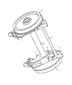
Fig. 2 shows a wheelset bearing of Fig. 1 in a perspective view,
seen from below;
Fig. 3 shows a plan view onto an alternative wheelset bearing
having brake actuators in a perspective view, seen from above;
Fig. 4 shows a wheelset bearing of Fig. 1 in a perspective view,
seen from below, having bearings inclined at an angle for the
connection to the truck frame; and
Fig. 5 shows a side view of a wheelset bearing of Fig. 4.
Detailed Description of the Exemplary Embodiments
Fig. 1 depicts a truck frame 8 having two wheelset bearings in
accordance with the invention, the front right-hand wheel 3 being
shown detached to reveal the bearing housing 7 and the primary
suspension, consisting of spring 5 and optionally in addition of
a damper 6 (instead of the damper 6 it would of course also be
CA 02908870 2015-12-11
54106-1918
= 12
possible to use self-damping springs 5). For illustrative
purposes, the wheelset guide principle of the motion link has
been chosen by way of example. The bearing housing 7 has an arm
that carries spring 5 and damper 6, as well as, on the opposite
side, a further arm having at its end a wheelset guide bushing 4
by which the wheelset is pivot-mounted in the truck frame 8. In
this instance, the wheelset axle 2 has four brake disks 9
arranged in two pairs. The associated brake actuators 10 are
mounted on the truck frame 8. The wheelset bearing, which
encloses the wheelset axle at its ends and is mounted in the
bearing housing 7, is not visible here. The two bearing
housings 7 are connected to the torsion spring 1.
Fig. 2 shows only the wheelset, consisting of two wheels 3 and
the wheelset axle 2 connecting these, and the two bearing
housings 7 from Fig. 1. The wheelset axle 2 is mounted in the
wheelset bearings 11. The torsion spring 1 is attached on the
underside of the arm, where the wheelset guide bushing 4 that is
press-fitted into the bearing housing 11 is provided. In this
case, the torsion spring 1 is form in a rod-shaped with a round
cross-section, the two ends being bent round through
approximately 90 so that the ends coincide with the two arms of
the bearing housing 7. In this arrangement, the ends are fixedly
connected to the bearing housing 7. The middle section of the
torsion spring 1 lies parallel and in proximity to the connection
between the two wheelset guide bushings 4 and in a plane normal
to the direction of travel.
Fig. 3 shows an alternative embodiment of a torsion spring 12
that is formed as straight and is connected directly to the
bearing housing 7. The torsion spring 12 is wider than it is
CA 02908870 2015-12-11
54106-1918
. 13
high, viewed in the direction of travel, and has caliper
brakes 10 on its top side that cooperate with the associated
pairs of brake disks 9. No further torsion spring, as for
instance in the form of the torsion spring 1 from Figs. 1 and 2,
is provided.
In this case, the torsion spring 12 lies roughly in a horizontal
plane with the wheelset axle 2. Viewed in the direction of
travel, the torsion spring lies largely inside the wheelset guide
bushings 4.
As shown in Figs. 4 and 5, a bearing 13 is provided in each of
the two wheelset guide bushings 4 for realizing the connection to
the frame 8 (see Fig. 1) of the truck. The axes of rotation 14 of
the bearing 13 include an angle with the longitudinal axis of the
middle section of the torsion spring 1; they are inclined
downward with respect thereto (or, as the case may be, to the
horizontal) inside the bearing housing 7. The angles are of equal
magnitude for the two bearings 13 of the same wheelset and are
symmetrical to the longitudinal median plane of the frame 8 of
the truck. The angle typically amounts to a few degrees and can
lie approximately in the range up to 20 .
The bearings 13 can be formed as journal or link bearings. The
bearing 13 enables the wheelset guide bushing 4 (and hence the
bearing housing 7) to rotate about the axis of rotation 14 of the
bearing 13. Engaging with the bearing 13 is, for example, a
motion link which is part of the frame of the truck 8 and which
consequently is rigidly connected at its other end to the frame 8
of the truck.
CA 02908870 2015-12-11
54106-1918
14
Thus, while there have been shown, described and pointed out
fundamental novel features of the invention as applied to a
preferred embodiment thereof, it will be understood that various
omissions and substitutions and changes in the form and details
of the devices illustrated, and in their operation, may be made
by those skilled in the art without departing from the spirit of
the invention. For example, it is expressly intended that all
combinations of those elements which perform substantially the
same function in substantially the same way to achieve the same
results are within the scope of the invention. Moreover, it
should be recognized that structures and/or elements shown and/or
described in connection with any disclosed form or embodiment of
the invention may be incorporated in any other disclosed or
described or suggested form or embodiment as a general matter of
design choice. It is the intention, therefore, to be limited
only as indicated by the scope of the claims appended hereto.