Note: Descriptions are shown in the official language in which they were submitted.
1
Description
Out-of-round pedicle screw
The present invention relates to a pedicle screw comprising a screw core
profile with a
cross-section which is out-of-round at least in parts.
Background of the Invention
A pedicle screw is a surgical instrument/implant for stabilizing the vertebral
column. In
backbone surgery, pedicle screws are frequently used for stabilizing
operations such as
for repositioning a sliding vertebra or for stiffening vertebrae. Their
usually self-tapping
thread facilitates the process of screwing the screw in the vertebral arch
roots of two or
more vertebrae. The screw head or the tulip is either supported on the screw
shaft in
movable fashion (polyaxial) by means of a ball joint or rigidly connected
(mono-axial) to
the thread.
Provided in the screw head/tulip is an axially extending, U-shaped recess
capable of
receiving a rod. Said rod is fixed in the screw head/tulip by means of a set
screw.
Hence, the pedicle screw may be used as an instrument to return a displaced
vertebra
(sliding vertebra) back to the correct position, for example. For stabilizing
the vertebral
column, four or more pedicle screws are interconnected by means of rods along
the
backbone axis. Pedicle screws having the previously described construction are
known
in the prior art from many disclosures to which reference is made in the
following
description. This is why a repeated description of the pedicle screw, in
particular of the
tulip and the traverse, may be omitted with reference to said commonly known
prior art.
Prior Art
Regarding the screw shaft, however, pedicle screw shapes are known from prior
art
which have different core cross-sections (expanding continuously or in step-
wise
manner) in the longitudinal direction of the shaft. This measure is supposed
to ensure
that a pedicle screw which is screwed in the vertebral arch root gets radially
braced in
particular in the outer/proximal head zone in the borehole and thus is able to
transmit
CA 2909350 2018-01-10
CA 02909350 2015-10-13
2
higher forces into the vertebra without coming loose. It was also contemplated
to
radially expand the screw flanks in the longitudinal direction of the shaft
toward the
screw head in a continuous or step-wise manner in order to achieve an
increasing
incising effect in the vertebral body. This is done with the aim to prevent
the pedicle
screw from breaking out.
Despite of these commonly known efforts in terms of providing an optimum
design of
the shaft and the screw flanks, the urgent problem of the reliable grip of the
pedicle
screw in the vertebra over a long period of time continues to exist. In
particular,
following defects in the prior art turn out to be particularly fatal:
- An insufficient secondary stability with respect to rotational forces
acting on the
pedicle screw,
- if the pedicle screw is torn out of the bone in case of tensile and/or
shearing
forces,
- stiff and slow screwing process,
- uncontrollability of the screwing process.
In fact, there is a variety of different screw shapes and screw constructions
in the field of
screw technology, but these are designed outside the field of medical
engineering with
regard to specific applications such as cooperating with wood, plastics,
plasterboards
and the like construction materials. Bone material is clearly different from
these, not only
due to its composition and strength but also because of the fact that it is a
material
which is still alive and constantly changes and renews its structure. In
addition,
conventional screws outside the field of medical engineering are exposed to
other loads
(mostly static loads) than in a medical application in the body of a patient.
This is why
they can be made from other materials which result in an optimum connection
with the
construction material concerned. In medical technology, this is not possible
(or only
partly possible) due to reasons of hygiene as well as biocompatibility. This
is why
technical solutions outside the field of medical engineering can not be
readily
transferred to bone screw constructions.
3
Brief Description of the Invention
On the basis of these problems, it is the object of the present invention to
provide a
bone screw, in particular a pedicle screw, by means of which higher forces can
be
reliably and permanently introduced into a patient's bone. In particular, the
bone screw
or pedicle screw is to be optimized preferably to the extent that a higher
secondary
stability in terms of rotational forces is achieved.
This object as well as further aims of the present invention are achieved by a
bone
screw according to the present disclosure. Advantageous configurations of the
invention
are subject-matter of the this disclosure.
The fundamental principle of the present invention is based on the
consideration to
subdivide the threaded shaft of a bone screw or pedicle screw into at least
two
longitudinal sections, i.e. a distal shaft portion and a (preferably directly)
adjoining
proximal shaft portion. It is exclusively the distal shaft portion which has -
with regard to
its thread core - a cross-sectional shape extending in the longitudinal
direction of the
distal shaft portion which deviates from a circular shape. Owing to this õout-
of-round"
cross-sectional shape of the thread core which is exclusively present in the
distal shaft
portion, the bone/pedicle screw is able to receive a defined surplus of
rotational forces
than in the case of a thread core with a continuous circular shape, without
coming loose
in the bone or further getting screwed into it. As the circular shape of the
thread core is
maintained in the proximal shaft portion, however, the bone/pedicle screw may
continue
to be firmly braced in the patient's bone in particular in the area adjoining
the bone and
in this way permanently transmit shearing forces into the bone. In this
context, reference
is made to the fact that the distal shaft portion has a defined section length
(approximately 0.5 times the total shaft length) with a (constant) small
(median) core
diameter. The proximal shaft portion also has a defined section length
(approximately
0.5 times the total shaft length) with a (constant) large (median) core
diameter.
Preferably, provision is made that the out-of-round core cross-sectional shape
represents a polygon further comprising preferably sharp-edged corners. This
enhances
the ability of receiving/transmitting rotational forces into the bone.
CA 2909350 2018-01-10
CA 02909350 2015-10-13
4
According to an aspect of the invention possibly to be claimed independently,
provision
may be made that the number of the corners changes over the longitudinal
extension of
the distal shaft portion. In this way, a square shape may be formed in the
distal zone
first, changing over into in a pentagonal or hexagonal shape in the middle
area of the
distal shaft portion. This will further enhance the load-bearing capacity in
terms of
rotational forces.
According to an aspect of the invention possibly to be claimed independently,
provision
may be made that the corners between respectively longitudinally adjacent
screw
threads are arranged one behind the other at the same angular position along
the distal
shaft portion. As an alternative to this, however, it is also possible that
the corners
between respectively longitudinally adjacent screw threads are arranged so as
to be
angularly staggered with respect to each other. In the latter case, provision
can be
made that the angular displacement amount and/or the angular displacement
direction
changes continuously and/or abruptly in the longitudinal direction of the
shaft. These
irregularities allow to introduce larger rotational forces into the bone and
there will be a
safe grip of the bone screw in the bone material.
According to an aspect of the invention possibly to be claimed independently,
the screw
shaft and preferably the distal shaft portion having the out-of-round core
diameter may
be manufactured by a thread whirling process by means of a thread whirling
tool. This
measure results in substantially sharp-edged corners on the core perimeter,
improving
the ability to transfer rotational forces into the bone.
It may be advantageous if the outer edges of the screw flanks have the shape
of a
continuous spiral even in the zone of the distal shaft portion. In particular,
it may be
advantageous if the outer edges of the screw flanks are formed without any
bends and
edges especially in the distal shaft portion. This guarantees a reliable screw
connection
to the bone and high tensile forces can be introduced into the bone via the
screw flanks
without the screw being torn out.
CA 02909350 2015-10-13
Description of the Figures
The invention will be explained in more detail below on the basis of preferred
exemplary
embodiments with reference to the accompanying Figures.
Fig. 1 shows a perspective view of the thread core of a bone screw, in
particular a
pedicle screw, according to a first preferred exemplary embodiment of the
invention
without thread flank and tulip,
Fig. 2 shows a cross-sectional view of the thread core in the distal shaft
portion of the
bone screw according to Fig. 1 without thread flank and tulip,
Fig. 3 shows the cross-section of the thread core in the distal shaft portion
of the bone
screw according to Fig. 1,
Fig. 4 shows a cross-sectional view of the thread core in the proximal shaft
portion of
the bone screw according to Fig. 1 without thread flank and tulip,
Fig. 5 shows the perspective view of the thread core of a bone screw, in
particular a
pedicle screw, according to a second preferred exemplary embodiment of the
invention
without thread flank and tulip,
Fig. 6 shows the perspective view of the thread core of a bone screw, in
particular a
pedicle screw, according to a third preferred exemplary embodiment of the
invention
without thread flank and tulip,
Fig. 7 shows in a perspective view the schematic longitudinal extension of the
longitudinal edges which are produced by the polygonal core cross-sectional
shape in
the distal shaft portion and
Fig. 8 shows the basic extension of the thread core of a bone screw according
to a
preferred exemplary embodiment of the invention.
CA 02909350 2015-10-13
6
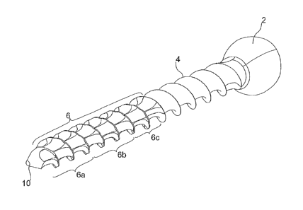
The bone screw illustrated in Fig. 1 to 3 preferably in the form of a pedicle
screw
according to a first preferred exemplary embodiment of the invention comprises
a screw
shaft 1 and a ball-head shaped screw head 2 on the proximal end of the screw
shaft 1.
The screw head 2 is adapted to be pivotally coupled to a cylindrical tulip
which is not
shown in further detail, said tulip being provided with an elongated slot
which is open
axially at one side starting from the proximal tulip end and is provided for
transversely
inserting a traverse or bar (likewise not shown in further detail). Such a
tulip
construction according to a polyaxial pedicle screw is well known from the
prior art, so
that reference can be made here to the pertinent prior art. Further, already
here it is
pointed to the fact that instead of the illustrated polyaxial pedicle screw a
mono-axial
pedicle screw of known design or a simple bone screw may be provided as well.
According to the invention, the screw shaft 1 is subdivided in several,
preferably two
longitudinal sections 4, 6. In the present case, a proximal longitudinal
section 4
immediately adjoining the screw head 2 in longitudinal direction has a larger
(median)
core diameter which is cylindrical according to this exemplary embodiment,
i.e. has a
continuously circular cross-section in longitudinal direction. Basically, the
proximal
longitudinal section 4 may have a core diameter which is constant over its
axial length.
It is also conceivable, however, that the core diameter decreases continuously
or in
step-wise manner from the screw head 2 toward the distal end.
The screw flanks which are not shown in Fig. 1 to 3 usually have a sharp-edged
outer
edge without any bends, the outer diameters of screw flanks preferably
following the
core diameter. This means that in case of a varying core diameter, the outer
diameters
of the screw flanks will vary in corresponding fashion. This ensures that the
screw
thread will always cut into the bone to a sufficient extent and in this way is
able to
introduce maximum tensile forces into the bone.
The proximal shaft portion 4 shown in Fig. 1 and 2 having a cylindrical core
cross-
section transitions into a distal shaft portion 6 in a middle area 8 of the
screw shaft 1;
this distal shaft portion has a (median) core diameter which is smaller than
the core
diameter of the proximal shaft portion 4. Here, it is referred to the fact
that both shaft
portions 4, 6 may alternatively have substantially the same core diameter,
too. Further,
the core diameter of the distal shaft portion 6 is shown in the present
exemplary
CA 02909350 2015-10-13
7
embodiment so as to be constant over the entire section length. It is also
conceivable,
however, that the core diameter of the distal shaft portion 6 is further
decreased
continuously or in step-wise manner toward the screw tip 10.
The important point in the present invention is that (exclusively) the distal
shaft portion 6
is realized with a core cross-section that deviates from the cylindrical shape
(circular
shape). In other words, the (small, median) core cross-section of the distal
shaft portion
6 has a polygonal shape over its entire length, preferably with equal legs. In
particular,
the (small, median) core cross-section according to Fig. 3 has five corners in
total, with
this polygonal shape adjoining the circular shape of the proximal shaft
portion 4
according to Fig. 4 essentially without any transition. Further, the outer
diameter of the
screw may be circular, especially also in the zone of the polygon portion
irrespectively
of the polygonal shape of the screw core (substantially without any bends), as
is
indicated in Fig. 6.
According to the first preferred exemplary embodiment, the five corners of the
polygonal
shape are always formed at the same angular position over the entire length of
the
distal shaft portion. This arrangement results according to Fig. 2 in five
axially parallel,
straight outer lines/edges 12. As an alternative according to a second
exemplary
embodiment of the present invention, it is however also possible to vary the
angular
positions of the corners along the distal shaft portion 6, as is schematically
shown in
particular in Fig. 5.
Accordingly, the corners of a polygonal core cross-sectional shape, starting
from the
screw tip 10 and proceeding in proximal direction, are initially continuously
twisted in
anti-clockwise direction and subsequently are continuously twisted in reverse
fashion in
clockwise direction. This results in S-shaped or zigzag-shaped, longitudinally
extending
outer lines/edges 12 on the screw core.
As an alternative or in addition to the previously described measures, the
distal shaft
portion 6 may be subdivided in several axial zones in which the (small,
median) core
cross-sections each have a polygonal shape with different numbers of corners
with
respect to one another, as is illustrated in Fig. 6. Accordingly, the distal
shaft portion 6
may be subdivided, for example, in three axial zones 6a, 6b, 6c, the number of
the
CA 02909350 2015-10-13
8
corners of the respective polygonal shape starting from the screw tip 10
changing from
four to five and then to six. Basically, zones comprising from two to any
number of
corners are conceivable. This results in a screw contour of the screw core as
it is
indicated in Fig. 7.
In order to be able to produce the polygonal cross-sectional shape of the
screw core in
precise manner, a thread whirling tool of known construction is employed
according to
the invention. According to this, the õout-of-round" and preferably polygonal
core cross-
section is manufactured in that the thread whirling tool within a rotation of
the bone
screw by 360 is repeatedly oscillated or moved around its own axis toward the
thread
core. The oscillating movement generated in this process preferably amounts to
between +1- 0.05 mm and +1- 1 mm. By way of example and in a preferred
embodiment
of the invention, the thread whirling tool (or alternatively the thread core)
may oscillate
between a feed length of 3.2mm and 3.7mm. Between these two feed lengths, the
corners are produced which are essentially sharp-edged depending on how fast
the
feed lengths are changed compared to the number of revolutions.
In the cylindrical, proximal shaft portion 4, the thread core will be machined
to a thread
core diameter of e.g. 4 mm within two full revolutions of the bone screw
around its axis.
This produces the uniform transition 8 from the distal shaft portion 6 to the
proximal
shaft portion 4.
Finally, Fig. 8 shows the cross-sectional profile of the screw core according
to a
preferred exemplary embodiment of the invention in principle. Accordingly, the
bone
screw according to the invention comprises the screw tip 10 which transitions
in conical
fashion into the distal shaft portion 6 which in the present case has a
constant, small
core diameter. Only this portion 6 having the constantly small core diameter
is provided
for the formation of the polygonal cross-sectional shape of the screw core. In
a middle
area of the screw shaft, the transition portion 8 is formed which has a
conically
expanding core cross-section, continuing into the proximal shaft portion 4
with a
constantly large core diameter (cylindrical shape). This proximal shaft
portion 4 has a
core cross-section of circular shape.
CA 02909350 2015-10-13
9
In summary, the disclosure relates to a medical bone screw in particular in
pedicle
screw design comprising a screw-and-thread shaft 1 which comprises a distal
shaft
portion 6 having a preferably smaller, but not necessarily a preferably
constant (median)
core diameter that transitions into a proximal shaft portion 4 having a
preferably larger,
but not necessarily a preferably constant (median) core diameter whose
proximal end is
provided with a screw head 2. According to the invention, the core cross-
sectional
shape along the distal shaft portion 6 is formed to be out-of-round at least
in parts,
preferably polygonal, and the core cross-sectional shape along the proximal
shaft
portion 4 is formed to be circular.