Note: Descriptions are shown in the official language in which they were submitted.
81792206
1
Expandable Balloon
This invention relates to an expandable balloon for insertion in a fluid
conduit of
the human or animal body.
Atherosclerosis affects the blood vessels of patients with coronary arterial
disease or with peripheral arterial disease. Peripheral arterial disease may
affect the
carotid or the arteries of the lower limbs. For example, peripheral arterial
disease in
the femoropopliteal artery often takes the form of total occlusions or
calcified,
obstructive lesions_ Percutaneous transluminal angioplasty (PTA) is often the
initial
treatment choice to restore lumen patency or to prepare a vessel, moderately
or
severely affected by atherosclerotic disease, for stenting. One of the major
problems
with PTA in such settings is an uncontrolled disruption of the atherosclerotic
plaque
leading to vessel dissection.
An alternative method to treat such lesions is to use a cutting/scoring
balloon.
The principle behind the cutting/scoring balloon is to apply a longitudinal
focal force to
the atherosclerotic plaque, which is understood to reduce the uncontrolled
disruption
of the atherosclerotic plaque associated with traditional PTA techniques. By
using a
cutting/scoring balloon the plaque may be disrupted in a controlled manner,
helping
to achieve the process of dilatation of the stenosis without the risk of
damaging the
vessel during the application of regular balloon angioplasty. In some cases it
is found
to be beneficial to provide for distal capture of displaced plaque fragments
to avoid
downstream embolization.
According to an aspect of the present invention, there is provided an
expandable balloon for insertion in a vessel of the human or animal body, the
balloon
being movable between a collapsed condition and an expanded condition, the
balloon comprising a plaque disrupting formation arranged to be on an outer
surface
of the balloon when in the expanded condition, and the balloon having, when in
the
Date Re9ue/Date Received 2020-08-10
81792206
la
expanded condition, a centre line which follows a substantially helical path,
wherein
the plaque disrupting formation is arranged helically on the balloon outer
surface with
substantially the same pitch as the helical centre line of the balloon.
According to another aspect, there is provided an expandable balloon for
insertion in a vessel of the human or animal body, the balloon being movable
between a collapsed condition and an expanded condition, the balloon having,
when
in the expanded condition, a centre line which follows a substantially helical
path, and
the balloon comprising hoop wires extending circumferentially of the balloon
when in
the expanded condition, the hoop wires being spaced apart from each other in
the
lengthwise direction of the balloon, wherein the balloon further comprises
lengthwise
extending members which extend helically around the balloon when in the
expanded
condition.
Viewed from a first aspect the invention provides an expandable balloon for
insertion in a vessel of the human or animal body, the balloon being movable
between a collapsed condition and an expanded condition, the balloon
comprising a
plaque disrupting formation arranged to be on an outer surface of the balloon
when in
the expanded condition, and the balloon having, when in the expanded
condition, a
centre line which follows a substantially helical path.
A balloon with a helical centreline may tend to exert on a vessel wall higher
stresses on the outer curvature of the helix. The plaque disrupting formation
can be
arranged on the balloon outer surface taking account of this effect.
The plaque disrupting formation may be a cutting or scoring blade, or it may
be
a wire. The wire may have various cross-sectional shapes, such as square or
triangular. The blade or wire may be formed from a shape memory material, such
as
Date Recue/Date Received 2021-04-06
CA 02909548 2015-10-15
WO 2014/177893
PCT/GB2014/051385
2
nitinol, or from a non shape memory metal The plaque disrupting formation may
be
capable of being deformed as the balloon moves from the collapsed condition to
the
expanded condition. The formation may be welded or otherwise joined to the
outer
surface of the balloon.
In certain embodiments, the helical centreline of the balloon rotates around a
longitudinal axis, and the plaque disrupting formation is arranged so that
when the
balloon is in the expanded condition it faces radially outwardly with respect
to the
longitudinal axis. It may sit on the radially outermost point on the balloon
cross-
section. It is expected that a balloon having a helical centreline (and hence
a helical
shape) will exert the greatest pressure when expanded where it faces radially
outwardly with respect to the longitudinal axis. Hence, by providing the
plaque
disrupting formation in this region a desired radially outward pressure for
plaque
disruption can be achieved.
A helix has a pitch and an amplitude. The pitch of the helical centre line may
be substantially constant along the length of the balloon. The pitch may vary
along
the length of the balloon. For example, the pitch in a region adjacent to a
longitudinal
end of the balloon may be longer than the pitch in a region nearer to the
middle of the
balloon. The amplitude of the helical centre line may be substantially
constant along
the length of the balloon. The amplitude may vary along the length of the
balloon.
For example, the amplitude in a region adjacent to a longitudinal end of the
balloon
may be smaller than the amplitude in a region nearer to the middle of the
balloon.
A helix may be considered as being left-handed or right-handed. The helical
centre line of the balloon may be left handed or right handed.
The plaque disrupting formation may be arranged helically on the balloon
outer surface. The helical arrangement may have the same handedness as the
helical centreline of the balloon, or it may have the opposite handedness to
the
helical centreline.
The plaque disrupting formation may be arranged helically on the balloon
outer surface with substantially the same pitch as the helical centreline of
the balloon.
It may have the same pitch but the opposite handedness. In certain
embodiments,
the plaque disrupting formation has substantially the same pitch as the
balloon
helical centreline, as well as the same handedness. In these arrangements, if
the
helices are in phase, then the plaque disrupting formation may be arranged so
that
when the balloon is in the expanded condition it faces radially outwardly with
respect
CA 02909548 2015-10-15
WO 2014/177893
PCT/GB2014/051385
3
to the longitudinal axis about which the helical centreline rotates. The
plaque
disrupting formation can then exert a relatively high pressure for plaque
disruption.
Alternatively, the plaque disrupting formation may have the same pitch and
handedness as the helical centreline, but it may be out of phase therewith.
The plaque disrupting formation may extend longitudinally of the balloon. It
can therefore disrupt plaque over a given length of a vessel when the balloon
is
expanded. When the balloon is in the expanded condition, the plaque disrupting
formation may extend continuously over a lengthwise portion of the balloon, or
it may
extend over a lengthwise portion of the balloon as a plurality of plaque
disrupting
formation portions arranged at longitudinal intervals. For example, a
plurality of
blades may be arranged at longitudinal intervals.
There may be a single plaque disrupting formation or there may be a plurality
of plaque disrupting formations. There may for example be three plaque
disrupting
formations. This would be a suitable number in the case of a balloon which has
a
three-wing configuration when in the collapsed condition.
If there is just one plaque disrupting formation, when considering a
transverse
section of the balloon when in the expanded condition, just the one plaque
disrupting
formation may be observed on the outer surface of the balloon. The one plaque
disrupting formation may be continuous over a lengthwise portion of the
balloon, or
may be provided as a plurality of plaque disrupting formation portions
arranged at
longitudinal intervals.
If there is a plurality of plaque disrupting formations, these may be provided
at
a circumferential interval or at circumferential intervals around the balloon
outer
surface. When considering a transverse section of the balloon, a plurality of
plaque
disrupting formations may be observed on the outer surface of the balloon. One
or
more of the plurality may be continuous over a lengthwise portion of the
balloon, or
may be provided as a plurality of plaque disrupting formation portions
arranged at
longitudinal intervals.
Each of the plural plaque disrupting formations may be arranged helically on
the balloon outer surface. Each may have the same pitch as the helical
centreline of
the balloon. Each may have the same handedness as the helical centreline, or
each
may have the opposite handedness of the helical centreline. One or more
formations
may have the same handedness as the helical centreline of the balloon, and one
or
more formations may have the opposite handedness. One of the helical plaque
CA 02909548 2015-10-15
WO 2014/177893
PCT/GB2014/051385
4
disrupting formations may be in phase with the balloon helical centreline, and
one or
more of the helical plaque disrupting formations may be out of phase
therewith.
The outer surface of the balloon will generally have a notional longitudinally
and helically extending line which when the balloon is in the expanded
condition
faces radially outwardly with respect to the longitudinal axis about which the
helical
centreline of the balloon rotates. The outer surface may be considered as
having a
notional substantially helically and longitudinally extending part (or
notional helical
strip) which has a width in the circumferential direction subtending an angle
with
respect to the helical centre line and along which said notional line extends
along a
locus of points each half way across the width. The notional line can be
regarded as
a centreline of the notional substantially helically and longitudinally
extending part.
The angle may be 30 0r25 0r20 or 15 or 10 or 5 degrees, for example.
Just one plaque disrupting formation may be provided on this part of the
balloon outer surface, or plural plaque disrupting formations may be provided
on this
part. The or each plaque disrupting formation may be continuous over a
lengthwise
portion of the balloon, or may be provided as a plurality of plaque disrupting
formation portions arranged at longitudinal intervals. Such formations may be
closely
spaced from each other in the circumferential direction. As this is a part of
the outer
surface which is expected to exert maximum pressure on the plaque as the
balloon
expands, it may be desirable to provide more than one plaque disrupting
formation
along this part. The plural formations may contribute to the plaque disrupting
efficiency by engaging with the vessel/plaque surface to ensure effective
direction of
the formation to the plaque surface thus maximising the force applied.
The balloon may comprise a central shaft. The balloon may thus comprise an
expandable wall which in the collapsed condition of the balloon lies close to
the shaft
and which is expandable radially outwardly from the shaft to cause the balloon
to
adopt the expanded condition thereof. In such arrangements, the expandable
wall
provides the balloon outer surface.
In certain embodiments, when the balloon is in the collapsed condition, it is
divided into a plurality of pleats which are wrapped around a central shaft.
Two or
more pleats may be provided. In one possible arrangement, three pleats are
provided, but less or more than three may be used. When the balloon is in a
pleated
state, the plaque disrupting formation may be provided on the balloon outer
surface
so as to face radially outwardly. This can avoid contact between the plaque
disrupting formation, which may for example comprise a sharp cutting blade,
and
CA 02909548 2015-10-15
WO 2014/177893
PCT/GB2014/051385
other portions of the balloon outer surface when it is in the collapsed
condition. This
can avoid damage to the balloon.
The pleats may each have a radially inner fold line, and the radially inner
fold
line may extend helically around the central shaft. If the fold line extends
helically
around the central shaft, then the pleats will also tend to follow a helical
configuration
when wrapped around the shaft. Therefore, the plaque disrupting formation on
the
balloon outer surface may follow a helical path when the balloon is in the
collapsed
condition. This is a convenient way of ensuring that the plaque disrupting
formation
faces radially outwardly when the balloon is in the collapsed condition.
The plaque disrupting formation may be provided adjacent to an exterior edge
of a pleat.
The plaque disrupting formation may be provided on the balloon outer surface
so as to be covered by at least one of the pleats when the balloon is in the
collapsed
condition. This arrangement can provide protection to the vessel.
In certain embodiments, the plaque disrupting formation is attached
continuously along its length to the balloon outer surface. However, as
discussed
below, there may be other attachment arrangements for the plaque disrupting
formation.
When the helical balloon is collapsed on to a central longitudinal axis, a
plaque disrupting formation (single or plural) appended to the balloon outer
surface
may not be able to follow the pleats as the fold line extends helically around
the
central shaft. Since the plaque disrupting formation is designed to be on the
outer
surface of a balloon having, when in the expanded condition, a centre line
which
follows a substantially helical path, the end to end length of the plaque
disrupting
formation will be longer than the (cone to cone) length of the collapsed
balloon along
its longitudinal axis. Physical and mechanical limitations of the materials of
the
plaque disrupting formation may prevent it from comfortably following the
helical path
(e.g. around the balloon pleats) when the balloon is in the collapsed
condition,
potentially resulting in kinking, twisting, or adverse interactions with the
balloon.
A possible solution is to keep the e.g. longitudinal centre portion of the
helical balloon
outer surface and the plaque disrupting formation independent of each other
(detached).
The plaque disrupting formation may be fixed at one end thereof relative to
the balloon outer surface and may not be attached to the outer surface over a
lengthwise extending portion of the balloon. In certain embodiments, the
plaque
CA 02909548 2015-10-15
WO 2014/177893
PCT/GB2014/051385
6
disrupting formation is attached at one end thereof to an end portion of the
balloon,
the end portion belonging for example to the balloon shaft or to the balloon
outer
surface, and is not attached to the outer surface over a lengthwise extending
portion
of the balloon.
The plaque disrupting formation may be fixed at both ends thereof relative to
the balloon outer surface. The plaque disrupting formation may be attached to
respective end portions of the balloon at each end of the formation. The
balloon may
collapse independently of the plaque disrupting formation (e.g. blade or
wire). The
plaque disrupting formation, such as a blade or wire, can then be wrapped over
the
longitudinal shaft of the collapsed balloon. This can avoid damage to the
balloon due
to pinching or kinking of the plaque disrupting formation. The plaque
disrupting
formation, such as a cutting or scoring blade or wire, can be configured using
a
shape memory material such that on expansion of the helical balloon, the
plaque
disrupting formation will be expanded outwards by the balloon of helical
centre line
and contact the outer surface of the balloon in any of the desired
configurations
described herein in order to exert the desired disrupting force on the plaque
of the
vessel.
In certain embodiments, the plaque disrupting formation is fixed at one end
thereof relative to the balloon outer surface, for example being attached at
said one
end to an end portion of the shaft or of the balloon outer surface such as the
balloon
neck, and comprises a holder at its other end, the holder being movable
relative to
the balloon outer surface. For example, the plaque disrupting formation may be
fixed
relative to the balloon outer surface at a distal end thereof and the holder
may be
provided at a proximal end. Distal and proximal ends may be considered with
respect to a catheter which is used to deliver the balloon to a treatment
site.
In certain embodiments, the holder is arranged to be axially movable. It may
be axially movable on a shaft of the balloon or a shaft of a delivery
catheter. The
holder may be arranged to be rotatably movable. It may be rotatably movable on
a
shaft of the balloon or a shaft of a delivery catheter. The holder may
comprise a ring.
A ring can be designed to be axially slidable and/or rotatable on a shaft.
A method of ensuring effective plaque disrupting formation and balloon
positioning in the collapsed configuration may be to fix the plaque disrupting
formation(s) to a longitudinal shaft of the balloon at the distal end only.
The plaque
disrupting formation(s) at the proximal end may be attached to a circular ring
which is
free to move over a shaft of e.g. the delivery catheter at the proximal end of
the
CA 02909548 2015-10-15
WO 2014/177893
PCT/GB2014/051385
7
helical balloon. The helical balloon can be collapsed independently of the
plaque
disrupting formation(s), avoiding damage to the balloon. As the plaque
disrupting
formation(s) is or are collapsed onto the balloon, the ring can allow the
collapsed
plaque disrupting formation(s) to take up a pre-set position configuration in
one of
two ways:
a) The circular ring can rotate around the shaft and allow the plaque
disrupting
formation(s) to wrap over the helical balloon without being constrained at one
end. This will allow plaque disrupting formation(s) which is or are long
enough
to be orientated in a spiral fashion which matches the substantially helical
path in the expanded configuration, to wrap around the collapsed balloon in a
manner that reduces the profile and minimises strains on the wire.
b) The circular ring can slide proximally (away from the balloon) along the
shaft
to allow the relatively long plaque disrupting formation(s) to collapse onto
the
balloon in a manner that reduces the profile and minimises strains on the
wire.
On expansion of the balloon, the ring will allow the plaque disrupting
formation(s) to
move readily and take a line which follows a substantially helical path along
the outer
surface of the helical balloon.
Known balloons, once they have been positioned at a treatment site, unwrap
from a crimped or collapsed state to an expanded state. As they do so they
impart a
shearing force on the vessel wall, generally in the circumferential direction
along the
vessel wall. The shearing forces during inflation have been linked to the
creation of
vessel dissections.
In certain embodiments of the invention, the balloon may comprise hoop
wires extending circumferentially of the balloon when in the expanded
condition. The
hoop wires may be spaced apart from each other in the lengthwise direction of
the
balloon. When the balloon is in the collapsed condition, the hoop wires would
be
folded and collapsed. During expansion, the hoop wires can contact the vessel
wall
preferentially to the balloon wall and limit the risk of vessel wall damage.
The inner diameter of the hoop wires may be smaller (generally only slightly
smaller) than the outer diameter of the inflated balloon. It should be noted
that the
balloon will normally be made of a material which is relatively inelastic,
such that the
balloon has an inflated diameter which is predetermined. The use of
constraining
hoop wires can limit the possibility for the balloon to impart damaging
shearing forces
on the vessel during expansion and as a result may reduce the likelihood of
vessel
CA 02909548 2015-10-15
WO 2014/177893
PCT/GB2014/051385
8
dissections. In the expanded state the hoop wires may cause the balloon to
bulge up
slightly between the hoop wires. The balloon would form small pillow shapes
between the hoop wires.
The balloon may be provided with at least one lengthwise extending member
connecting to at least some of the hoop wires. This can provide a structure
holding
the hoop wires in place. The plaque disrupting formation may act as such a
lengthwise extending member, or there be an additional lengthwise extending
member, such as a lengthwise extending wire. A lengthwise extending wire may
extend helically around the balloon when in the expanded state, as well as
lengthwise of the balloon.
When it is desired to withdraw the balloon from the vessel, the balloon is
collapsed and the lengthwise extending member may be used to pull the hoop
wires
out of the vessel.
In certain embodiments, a plurality of lengthwise extending members are
provided, which may be circumferentially spaced around the balloon.
The hoop wires may be manufactured from a flexible material with good
elastic properties, for example the super-elastic alloy nitinol or a similar
material.
Viewed from a second aspect, the invention provides an expandable balloon
for insertion in a vessel of the human or animal body, the balloon being
movable
between a collapsed condition and an expanded condition, the balloon having,
when
in the expanded condition, a centre line which follows a substantially helical
path, and
the balloon comprising hoop wires extending circumferentially of the balloon
when in
the expanded condition, the hoop wires being spaced apart from each other in
the
lengthwise direction of the balloon.
Such a balloon may be used for example in percutaneous transluminal
angioplasty (PTA) and so may not have a plaque disrupting formation as
described
herein. A vessel may be expanded to a helical shape corresponding to the shape
of
the balloon. The balloon may be used to expand a stent to a helical shape
corresponding to the shape of the balloon. The stent may be biased to adopt
substantially the same helical shape as the balloon, for example by being made
of a
shape memory material, or it may be plastically deformed by the balloon to
adopt the
helical shape thereof.
In other embodiments, the balloon may have such a plaque disrupting
formation, so as then to be usable as a cutting or scoring balloon. It may
have any of
CA 02909548 2015-10-15
WO 2014/177893
PCT/GB2014/051385
9
the various optional features described above in relation to the balloon with
the
plaque disrupting formation.
Considering the balloon of the second aspect, when the balloon is in the
collapsed condition, the hoop wires would be folded and collapsed. During
expansion, the hoop wires can contact the vessel wall preferentially to the
balloon
wall and limit the risk of vessel wall damage.
The inner diameter of the hoop wires may be smaller (generally only slightly
smaller) than the outer diameter of the inflated balloon. It should be noted
that the
balloon will normally be made of a material which is relatively inelastic,
such that the
balloon has an inflated diameter which is predetermined. The use of
constraining
hoop wires can limit the possibility for the balloon to impart damaging
shearing forces
on the vessel during expansion and as a result may reduce the likelihood of
vessel
dissections. In the expanded state the hoop wires may cause the balloon to
bulge up
slightly between the hoop wires. The balloon would form small pillow shapes
between the hoop wires.
The balloon of the second aspect may be provided with at least one
lengthwise extending member connecting to at least some of the hoop wires.
This
can provide a structure holding the hoop wires in place. The inner diameter of
the
lengthwise extending member may be smaller (generally only slightly smaller)
than
the outer diameter of the inflated balloon. In the case of embodiments forming
pillow
shapes where the balloon bulges up, the pillow shapes will have a modified
shape,
as the balloon will be constrained by both the hoop wires and the lengthwise
extending member.
The lengthwise extending member of the balloon of the second aspect may
be a lengthwise extending wire. A lengthwise extending wire may extend
helically
around the balloon when in the expanded state, as well as lengthwise of the
balloon.
When it is desired to withdraw the balloon from the vessel, the balloon is
collapsed and the lengthwise extending member may be used to pull the hoop
wires
out of the vessel.
In certain embodiments, a plurality of lengthwise extending members are
provided, which may be circumferentially spaced around the balloon.
The hoop wires may be manufactured from a flexible material with good
elastic properties, for example the super-elastic alloy nitinol or a similar
material.
The invention also extends to methods of using the expandable balloon of the
first aspect or the second aspect.
CA 02909548 2015-10-15
WO 2014/177893
PCT/GB2014/051385
Viewed from another aspect, related to the first aspect, the invention
provides
a method of treating a plaque in a vessel of the human or animal body, the
method
comprising deploying a balloon in a collapsed condition to a treatment site
and
expanding the balloon, the balloon comprising a plaque disrupting formation on
an
outer surface thereof, so that when the balloon is in the expanded condition
the
plaque disrupting formation exerts pressure on the plaque, and the balloon
having,
when in the expanded condition, a centreline which follows a substantially
helical
path.
The balloon used in the treatment method may have the various optional
features described herein.
The plaque disrupting formation on the outer surface of the balloon may
extend generally helically to follow the shape of the plaque. One method may
therefore comprise determining the shape of a plaque, and using a balloon with
a
plaque disrupting formation extending helically generally to follow the shape
of the
plaque. The shape of the plaque may be determined by suitable scanning
techniques.
Certain preferred embodiments of the invention will now be described by way
of example and with reference to the accompanying drawings, in which:
Figure 1 shows a perspective view of a first embodiment of an expandable
balloon;
Figure 2 shows a perspective view of a second embodiment of an expandable
balloon;
Figure 3 shows perspective view of a third embodiment of an expandable
balloon;
Figure 4 shows a cross-sectional view of the second embodiment when the
balloon is in the collapsed condition;
Figure 5 shows a fourth embodiment of an expandable balloon;
Figure 6 shows a fifth embodiment of an expandable balloon;
Figure 7 shows two manners of operation of the fifth embodiment;
Figure 8 shows a perspective view of a sixth embodiment of an expandable
balloon;
Figure 9 shows a detail of Figure 8, to an enlarged scale;
Figure 10 shows a perspective view of a seventh embodiment of an
expandable balloon; and
Figure 11 shows a detail of Figure 10, to an enlarged scale.
CA 02909548 2015-10-15
WO 2014/177893
PCT/GB2014/051385
11
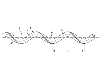
Figure 1 shows an expandable balloon 1 having a wall 2 with an outer surface
3. A plaque disrupting formation 4 is provided on the outer surface 3. The
formation
may be a cutting or scoring blade or it may be a wire, e.g. made of a shape
memory
alloy such as nitinol.
The balloon 1 has a helical axis 5 which rotates helically about a
longitudinal
axis 6. The balloon is shown in an expanded condition ex viva When the balloon
is
expanded in vivo it may not adopt the exact shape shown, as it will be
constrained by
the vessel and any plaque which is intended to be disrupted by the balloon.
The helical centreline 5 of the balloon has a pitch P. In this embodiment the
plaque disrupting formation 4 has the same pitch P. The plaque disrupting
formation
4 is arranged so that it faces radially outwardly with respect to the
longitudinal axis 6.
This means that it is likely to be on the part of the balloon which exerts
greatest
pressure on the vessel and any plaque as the balloon is expanded.
The balloon 1 shown in Figure 2 is similar to that of Figure 1, except that it
has three plaque disrupting formations 4a, 4b and 4c. These are provided on
the
outer surface of the balloon at equal circumferential spacings from each
other. Each
formation 4a, 4b, 4c has the same helical pitch P as the helical centreline 5
of the
balloon. Plaque disrupting formation 4a is arranged to face radially outwardly
with
respect to the longitudinal axis 6.
The balloon 1 shown in Figure 3 has an outer wall 2 with an outer surface 3.
On the outer surface 3 plaque disrupting formations 4a, 4b and 4c are
provided. The
helical centreline 5 of the balloon is a right-handed helix, whereas the
plaque
disrupting formations 4a-4c are provided on the balloon outer surface 3 in a
left-
handed helical configuration.
Figure 4 shows a cross-sectional view of the balloon of Figure 2 when in a
collapsed condition. The balloon is collapsed onto a central shaft 7. It is
formed into
three pleats 8 each of which has a radially inner fold line 9. The fold lines
9 extend
helically around the central shaft 7. They thus extend along the shaft and
around it.
Each of the plaque disrupting formations 4a-4c is provided adjacent to a tip
10 of
each pleat 8. The formations 4a-4c face radially outwardly with respect to the
central
shaft 7. This arrangement ensures that the plaque disrupting formations 4a-4c
do
CA 02909548 2015-10-15
WO 2014/177893
PCT/GB2014/051385
12
not engage the wall of the balloon other than where they are attached thereto.
Therefore damage to the balloon surface in the collapsed condition can be
avoided.
During deployment, the collapsed balloon shown in Figure 4 may be
contained in a sleeve until the balloon is located at the deployment site. The
sleeve
is then withdrawn and the balloon may be expanded. The plaque disrupting
formation or formations then engage the plaque and cut or score or otherwise
weaken it. In the case that the plaque disrupting formation faces radially
outwardly
with respect to the longitudinal axis 5, the required force to rupture the
plaque may
be achieved with lower balloon inflation pressure and this may be beneficial
in
limiting collateral damage to the vessel within which the treatment is being
conducted.
Figure 5 shows a plaque disrupting formation comprising a wire 4 which is
fixed at a distal end 11 to the balloon outer surface 3 and is fixed at a
proximal end
12 to the balloon outer surface 3. The balloon 1 is supported on a shaft 7.
The
balloon 1 is shown in the collapsed condition and the wire 4 is shown as it
would be
when the balloon is expanded. During delivery on the end of a catheter both
the
balloon wall 2 and the wire 4 could be constrained inside a sleeve (not
shown).
Figure 6 shows a plaque disrupting formation comprising a wire 4 which is
fixed at a distal end 11 to the balloon outer surface 3 and is provided at a
proximal
end 12 with a ring 13 which is free to move on the shaft 7. The balloon 1 is
shown in
the collapsed condition and the wire 4 is shown as it would be when the
balloon is
expanded. During delivery on the end of a catheter both the balloon wall 2 and
the
wire 4 could be constrained inside a sleeve (not shown).
Figure 7a shows a first manner of operation of a balloon as seen in Figure 6.
The balloon of Figure 6 is shown in the collapsed condition. Compared to the
configuration of Figure 6, the ring 13 is rotated relative to the fixed distal
end 11 of
the wire 4, so as to wrap or wind the wire 4 over the collapsed balloon. This
reduces
the transverse profile of the balloon.
Figure 7b shows a second manner of operation of a balloon as seen in Figure
6. The balloon of Figure 6 is shown in the collapsed condition. Compared to
the
configuration of Figure 6, the ring 13 is positioned further from the fixed
distal end 11
of the wire 4, so as to wrap or wind the wire 4 over the collapsed balloon.
This is
achieved by the ring having slid proximally along the shaft 7, away from the
distal
end 11. This reduces the transverse profile of the plaque disrupting formation
and
the balloon.
CA 02909548 2015-10-15
WO 2014/177893
PCT/GB2014/051385
13
The balloon 1 shown in Figure 8 is similar to that of Figure 2, with three
plaque disrupting formations 4a, 4b and 4c. These are provided on the outer
surface
of the balloon at equal circumferential spacings from each other. Each
formation 4a,
4b, 4c has the same helical pitch P as the helical centreline 5 of the
balloon. Plaque
disrupting formation 4a is arranged to face radially outwardly with respect to
the
longitudinal axis 6.
The balloon of Figure 8 additionally has hoop wires 14 extending
circumferentially of the balloon when in the expanded condition. The hoop
wires 14
are spaced apart from each other in the lengthwise direction of the balloon.
When
the balloon is in the collapsed condition, the hoop wires 14 would be folded
and
collapsed. During expansion, the hoop wires 14 can contact the vessel wall
preferentially to the balloon wall and limit the risk of vessel wall damage.
As can be seen in Figure 9, which shows a detail of the balloon of Figure 8 to
an enlarged scale, the inner diameter of the hoop wires 14 is smaller than the
outer
diameter of the inflated balloon, i.e. the outer diameter it would have when
inflated
without being constrained by the hoop wires. It should be noted that the
balloon will
normally be made of a material which is relatively inelastic, such that the
balloon has
an unconstrained inflated diameter which is predetermined. The use of
constraining
hoop wires can limit the possibility for the balloon to impart damaging
shearing forces
on the vessel during expansion and as a result may reduce the likelihood of
vessel
dissections.
In the expanded state the hoop wires cause the balloon to bulge up slightly
between the hoop wires 14. The balloon forms pillow shapes 15 between the hoop
wires. These are present but not shown in Figure 8, and can be seen in the
enlarged
view of Figure 9. The plaque disrupting formations, in the form of helical
wires as
seen in Figures 8 and 9, sit on the balloon outer surface 3 and so in use make
contact with the vessel wall.
The balloon of Figures 8 and 9 is an exemplary embodiment of both the first
and second aspects of the invention.
The balloon of Figures 10 and 11 is an exemplary embodiment of the second
aspect of the invention. These show an expandable balloon 1 for insertion in a
vessel of the human or animal body, the balloon being movable between a
collapsed
condition and an expanded condition, the balloon having, when in the expanded
condition, a helical axis 5 which rotates helically about a longitudinal axis
6, and the
balloon comprising hoop wires 14 extending circumferentially of the balloon
when in
CA 02909548 2015-10-15
WO 2014/177893
PCT/GB2014/051385
14
the expanded condition, the hoop wires 14 being spaced apart from each other
in the
lengthwise direction of the balloon.
When the balloon is in the collapsed condition, the hoop wires 14 would be
folded and collapsed. During expansion, the hoop wires 14 can contact the
vessel
wall preferentially to the balloon wall and limit the risk of vessel wall
damage.
As can be seen in Figure 11, which shows a detail of the balloon of Figure 10
to an enlarged scale, the inner diameter of the hoop wires 14 is smaller than
the
outer diameter of the inflated balloon, i.e. the outer diameter it would have
when
inflated without being constrained by the hoop wires. It should be noted that
the
balloon will normally be made of a material which is relatively inelastic,
such that the
balloon has an unconstrained inflated diameter which is predetermined. The use
of
constraining hoop wires can limit the possibility for the balloon to impart
damaging
shearing forces on the vessel during expansion and as a result may reduce the
likelihood of vessel dissections.
The balloon of Figures 10 and 11 has lengthwise extending members in the
form of helical wires 16a, 16b and 16c, which are connected to the hoop wires
14.
The helical wires are circumferentially spaced around the balloon. The inner
diameter of the helical wires is smaller than the outer diameter of the
inflated balloon.
Pillow shapes 17 are formed where the balloon bulges up between the
constraints of
both the hoop wires 14 and the helical wires 16a, 16b and 16c. The pillow
shapes
are present but not shown in Figure 10, and can be seen in the enlarged view
of
Figure 11. In use, once the balloon is fully expanded, the helical wires 16a,
16b and
16c do not make contact with the vessel wall.
When it is desired to withdraw the balloon from the vessel, the balloon is
collapsed and the helical wires 16a, 16b and 16c may be used to pull the hoop
wires
out of the vessel.
The balloon of Figures 10 and 11 may be used for example in percutaneous
translurninal angioplasty (PTA) and does not have plaque disrupting
formations. A
vessel may be expanded to a helical shape corresponding to the shape of the
balloon. The balloon may be used to expand a stent to a helical shape
corresponding to the shape of the balloon. The stent may be biased to adopt
substantially the same helical shape as the balloon, for example by being made
of a
shape memory material, or it may be plastically deformed by the balloon to
adopt the
helical shape thereof.
CA 02909548 2015-10-15
WO 2014/177893
PCT/GB2014/051385
In some instances a plaque may have a generally helical pattern in the
vessel. An optimal plaque disrupting balloon design can take account of the
helical
nature of the plaque. For example, it may follow the morphology of the plaque,
or it
may be arranged with opposite handedness to the helical morphology of the
plaque
so as to tend to cut across it.