Note: Descriptions are shown in the official language in which they were submitted.
CA 02909607 2015-10-15
WO 2014/149481 PCT/US2014/018800
AN EYE IMAGING APPARATUS WITH A WIDE FIELD OF VIEW
AND RELATED METHODS
BACKGROUND OF THE INVENTION
[001] Various embodiments of the invention relate generally to an eye imaging
apparatus and related methods, and for example to an eye imaging apparatus
with a wide field of
view and related methods.
[002] Eyes are among the most valued human organs that play indispensable
roles in
life. Likewise, eye diseases and vision loss in general are serious problems.
Moreover, eye
diseases and vision problems among children, especially new-born babies, can
have severe and
far-reaching implications. For infants and small children, the visual centers
in the brain are not
fully mature. For the visual centers in the brain to develop properly, proper
input from both eyes
is desirable. Therefore good vision can be an important factor in the proper
physical
development and educational progress.
[003] Undetected eye problems in infants and others may result in irreversible
loss of
vision. Early detection and diagnosis provide the best opportunity for
treatment and prevention
of vision loss.
[004] In eye examinations, eye imaging apparatus has become increasingly
important.
Since retinal and optic nerve problems are among the leading causes in vision
loss, eye imaging
apparatus capable of imaging a posterior segment of the eye can be
particularly useful.
Moreover, an eye imaging apparatus with a wide field of view can offer the
benefit of enabling
evaluation of pathologies located on the periphery of the retina.
1
CA 02909607 2015-10-15
WO 2014/149481 PCT/US2014/018800
SUMMARY OF THE INVENTION
[005] Various embodiments disclosed herein include, although are not limited
to, an eye
imaging apparatus with a wide field of view, which may be, for example, from
60 degree to 180
degree.
[006] Various embodiments, for example, may comprise an apparatus comprising a
housing and a light source disposed inside the housing to illuminate an eye.
The apparatus can
also include an optical imaging system. The system can include an optical
window at a front end
of the housing with a concave front surface for receiving the eye. The system
can also include
an imaging lens disposed rearward the optical window and optically aligned
with the optical
window along an optical imaging path. The optical imaging system can have an
optical axis.
The apparatus can comprise a light conditioning element in the housing having
at least one
multi-segment surface positioned behind the peripheral portion of the optical
window. The light
conditioning element can be configured to receive light from the light source
and direct said light
to the eye. The apparatus can include an image sensor in the housing disposed
to receive an
image of the eye from the optical imaging system.
[007] Various other embodiments comprise an eye imaging apparatus including a
housing and an optical window at a front end of the housing. The apparatus can
comprise a light
conditioning element having at least one multi-segment surface positioned
behind the peripheral
portion of the optical window. The light conditioning element can be
configured to receive light
from a light source and direct light to an eye.
2
CA 02909607 2015-10-15
WO 2014/149481 PCT/US2014/018800
[008] In various embodiments, a light conditioning element for an eye imaging
apparatus for illuminating an anatomical feature in a medical examination is
disclosed. The
element can comprise a body having front surface, a back surface, an inner
side surface and an
outer side surface. The inner side surface and the outer side surface can
comprise at least one
multi-segment surface. The light conditioning device can be configured to
receive light from a
light source and direct light to an eye.
[009] Various embodiments disclose an eye imaging apparatus employing
sequential
illumination. The apparatus can comprise a housing and a light source disposed
inside the
housing and having a plurality of light emitting elements configured to
illuminate different
portions of an eye time-sequentially. The apparatus can include an optical
imaging system inside
the housing. The optical imaging system can comprise an optical window at a
front end of the
housing. The system can also include an imaging lens positioned behind the
optical window and
optically aligned with the optical window. An image sensor can be configured
to receive a
plurality of images of the eye with a same field of view through the optical
imaging system while
each portion of the eye is illuminated time-sequentially.
[0010] In some other embodiments, a compact eye imaging apparatus includes a
housing
and a light source disposed inside the housing to illuminate an eye. The
apparatus can include an
optical imaging system. The system can include an optical window with a radius
of curvature
closely matching a curvature of a cornea of the eye at a front end of the
housing. An imaging
lens can be optically aligned with the optical window. The imaging lens can be
positioned
behind and separated from the optical window by a gap. The system can include
at least first and
second relay lenses. At least one miniature lens with a clear aperture size
less than 5 mm can be
3
CA 02909607 2015-10-15
WO 2014/149481 PCT/US2014/018800
configured to form the image of the eye based on light received from the at
least first and second
relay lenses. A miniature image sensor with a format less than 1/1.5" can be
configured to
receive the image of the eye formed by the at least one miniature lens.
[0011] Various other embodiments comprise an eye imaging system comprising an
eye
imaging apparatus comprising a housing and a light source disposed inside the
housing and
having a plurality of light emitting elements. The light emitting elements can
be configured to
illuminate different portions of an eye time-sequentially. The eye imaging
system can include an
optical imaging system. The optical imaging system can include an optical
window at a front
end of the housing. An imaging lens can be positioned behind the optical
window and optically
aligned with the optical window. An image sensor can be configured to receive
a plurality of
images of the eye with a same field of view through the optical imaging system
while each
portion of the eye is illuminated time-sequentially. A memory can be
configured to temporarily
store the plurality of images. A computing and communication unit can be
configured to receive
and transmit the plurality of images. The eye imaging system can further
include an image
computing module configured to receive the plurality of images from and
exchange data with the
eye imaging apparatus. The image computing module can comprise an image
processing unit
configured to generate a set of instructions to process the plurality of
images to create a
composite image of the eye.
[0012] A method of imaging an eye is also disclosed. The method can include
activating
a light source to illuminate an eye. An optical window can be contacted with a
cornea of the eye.
The method can further include conditioning light received from the light
source by a light
conditioning element having at least one multi-segment surface. The light
conditioning device
4
CA 02909607 2015-10-15
WO 2014/149481 PCT/US2014/018800
can be configured to receive light from the light source and direct light to
the eye. The method
can include imaging the eye through an optical imaging system comprising said
optical window
and an imaging lens. The imaging lens can be positioned behind the optical
window and can be
optically aligned with the optical window. The method can comprise receiving
an image of the
eye through the optical imaging system by an image sensor.
[0013] A method of imaging an eye configured for sequential illumination is
also
disclosed. The method can comprise varying an intensity of a plurality of
light emitting elements
over time to illuminate different portions of an eye. The method can further
include imaging the
eye through an optical imaging system comprising an optical window and an
imaging lens. The
optical window can be configured to be in contact with a cornea of the eye.
The imaging lens
can be positioned behind the optical window and optically aligned with the
optical window. The
method can include receiving a plurality of images of the eye with a same
field of view through
the optical imaging system while each portion of the eye is illuminated time-
sequentially by an
image sensor. The plurality of images can be processed to create a composite
image of the eye
from the plurality of images.
[0014] A stereo eye imaging apparatus is also disclosed. The stereo eye
imaging
apparatus can include a housing and a light source disposed inside the housing
to illuminate an
eye. The stereo eye imaging apparatus can also comprise an optical imaging
system. The
optical imaging system can include an optical window at a front end of the
housing with a radius
of curvature closely matching a radius of curvature of a cornea of the eye. An
imaging lens can
be positioned behind the optical window and optically aligned with the optical
window. A light
conditioning device can be positioned behind the peripheral portion of the
optical window that is
CA 02909607 2015-10-15
WO 2014/149481 PCT/US2014/018800
configured to receive light from the light source and direct light to the eye.
A first camera and a
second camera can be configured to capture a first image and a second image of
the eye through
the optical imaging system. Extensions of a first optical axis of the first
stereo camera and of a
second optical axis of the second stereo camera can be converged onto the eye
with a convergent
angle.
[0015] A hermetically sealed eye imaging apparatus is also disclosed. The
hermetically
sealed eye imaging apparatus can include a housing with a front end and a
light source disposed
inside the housing to illuminate an eye. The hermetically sealed eye imaging
apparatus can
include an optical imaging system. The optical imaging system can include an
optical window at
the front end with a concave front surface for receiving the eye. The optical
imaging system can
also include an imaging lens disposed rearward the optical window and
optically aligned with
the optical window along an optical imaging path. The optical imaging system
can have an
optical axis. The hermetically sealed eye imaging apparatus can comprise a
hermetical seal
between the optical window and the front end filled with a hermetically
sealing material. An
image sensor in the housing can be disposed to receive an image of the eye
from the optical
imaging system.
[0016] In some other embodiments, an eye imaging apparatus comprises a housing
with a
front end having an inner side surface comprising an alignment edge and a
reservoir edge
disposed at the front end. The eye imaging apparatus can include a light
source disposed inside
the housing to illuminate an eye. The eye imaging apparatus can further
comprise an optical
imaging system. The optical imaging system can include an optical window at
the front end with
a concave front surface for receiving the eye. The optical imaging system can
also comprise an
6
CA 02909607 2015-10-15
WO 2014/149481 PCT/US2014/018800
imaging lens disposed rearward the optical window and optically aligned with
the optical
window along an optical imaging path, the optical imaging system having an
optical axis. The
optical window can be separated from the alignment edge with a first gap. The
optical window
can be separated from the reservoir with a second gap larger than the first
gap, configured to be a
reservoir of a sealing material. An image sensor in the housing can be
disposed to receive an
image of the eye from the optical imaging system.
[0017] Other embodiments also comprise an eye imaging apparatus comprising a
housing
with a front end comprising an inner side surface comprising an alignment edge
and a reservoir
edge disposed near the front end. The eye imaging apparatus can include a
light source disposed
inside the housing to illuminate an eye. The eye imaging apparatus can include
an optical
imaging system. The optical imaging system can include an optical window at
the front end with
a concave front surface for receiving the eye. The optical imaging system can
comprise an
imaging lens disposed rearward the optical window and optically aligned with
the optical
window along an optical imaging path, said optical imaging system having an
optical axis. The
optical window can be separated from the alignment edge with a first gap. The
optical window
can be separated from the reservoir with a second gap larger than the first
gap, configured to be a
reservoir of a sealing material. A plurality of balls can be disposed between
the housing and the
optical windows. An image sensor in the housing can be disposed to receive an
image of the eye
from the optical imaging system.
[0018] Various embodiments comprise an eye imaging apparatus comprising a
housing
with a front end comprising a distal section around an optical window
comprising a first
material. A proximal section can comprise a second material. The front end can
also include a
7
CA 02909607 2015-10-15
WO 2014/149481 PCT/US2014/018800
bond, wherein the distal section is connected with the proximal section by the
bond. The eye
imaging apparatus can include a light source disposed inside the housing to
illuminate an eye.
The eye imaging apparatus can include an optical imaging system. The optical
imaging system
can comprise the optical window at the front end with a concave front surface
for receiving the
eye. The optical imaging system can also include an imaging lens disposed
rearward the optical
window and optically aligned with the optical window along an optical imaging
path, said
optical imaging system having an optical axis. An image sensor in the housing
can be disposed
to receive an image of the eye from the optical imaging system.
[0019] Some embodiments of a hermetically sealed eye imaging apparatus with a
hermetically sealed removable front imaging module are also disclosed. The
hermetically sealed
eye imaging apparatus can include a housing and a light source disposed inside
the housing to
illuminate an eye. The hermetically sealed eye imaging apparatus can include a
hermetically
sealed removable front imaging module with a front end and a rear end. The
hermetically sealed
removable front imaging module can include an optical imaging system. The
optical imaging
system can comprise a first optical window at the front end with a concave
front surface for
receiving the eye. The optical imaging system can also include an imaging lens
disposed
rearward the optical window and optically aligned with the optical window
along an optical
imaging path. The hermetically sealed eye imaging apparatus can include a
first hermetical seal
between the first optical window and the front end filled with a first
hermetically sealing
material. The hermetically sealed eye imaging apparatus can include a second
optical window at
the rear end. The hermetically sealed eye imaging apparatus can include a
second hermetical
seal between the second optical window and the rear end filled with a second
hermetically
8
CA 02909607 2015-10-15
WO 2014/149481 PCT/US2014/018800
sealing material. A main module can comprise an image sensor in the housing
disposed to
receive an image of the eye from the optical imaging system. The hermetically
sealed removable
front imaging module can be capable of being repeatedly attached to and
removed from the main
module.
[0020] In some embodiments, an eye imaging apparatus comprises a housing with
a front
end comprising an inner side surface comprising an alignment edge and a
reservoir edge
disposed at the front end. The eye imaging apparatus can comprise a light
source disposed inside
the housing to illuminate an eye. The eye imaging apparatus can comprise an
optical imaging
system. The optical imaging system can include an optical window at the front
end with a
concave front surface for receiving the eye. The optical imaging system can
also include an
imaging lens disposed rearward the optical window and optically aligned with
the optical
window along an optical imaging path, said optical imaging system having an
optical axis. The
alignment edge can be perpendicular to a side surface of the optical window.
The optical
window can be separated from the reservoir edge with a gap configured to be a
reservoir of a
sealing material. An image sensor in the housing can be disposed to receive an
image of the eye
from the optical imaging system.
[0021] In certain embodiments, the eye imaging apparatus comprises a housing,
a light
source inside the housing, an optical imaging system, a light conditioning
element and an image
sensor. The optical imaging system includes an optical window configured to be
in contact with
a cornea of the eye on a forward said of the optical window and an imaging
lens positioned
rearward of the optical window and optically aligned with the optical window.
The light
conditioning element comprises a multi-segment surface and is positioned
behind the peripheral
9
CA 02909607 2015-10-15
WO 2014/149481 PCT/US2014/018800
portion of the optical window and configured to receive light from the light
source and direct
light to the eye. The image sensor is configured to receive an image of the
eye through the
optical imaging system.
[0022] Various embodiments disclosed herein include an eye imaging apparatus
with a
wide field of view configured to provide sequential illumination. The eye
imaging apparatus
comprises a plurality of light emitting elements, an optical imaging system,
and an image sensor.
The plurality of light emitting elements is configured to illuminate each
portion of an eye time-
sequentially. The image sensor is configured to receive a plurality of images
of the eye with a
same wide field of view through the optical imaging system while each portion
of the eye is
illuminated time-sequentially. In some embodiments, the eye imaging apparatus
further
comprises an image processing unit. In some embodiments, the eye imaging
apparatus may
transfer the plurality of images to other computing devices or internet based
devices that include
an image processing unit. The image processing unit is configured to generate
a set of
instructions to process the plurality of images to create a single clear image
of the eye.
[0023] Various embodiments disclosed herein include an eye imaging system with
a
wide field of view. The eye imaging system comprises an eye imaging apparatus
and an image
computing module. The eye imaging apparatus comprising a plurality of light
emitting elements,
an optical imaging system, an image sensor, a memory, and a computing and
communication
unit. The memory is configured to temporarily store the plurality of images.
The computing and
communication unit is configured to receive and transmit the image. The
imaging computing
module is configured to receive the plurality of images from and exchange data
with the eye
imaging apparatus. The image computing module further includes an image
processing unit
CA 02909607 2015-10-15
WO 2014/149481 PCT/US2014/018800
configured to generate a set of instructions to process the plurality of
images to create a single
clear image of the eye.
[0024] Various embodiments disclosed herein include a method of imaging an eye
with a
wide field of view. The method comprises activating a light source to
illuminate an eye,
conditioning the light source using a light conditioning element with a multi-
segment surface,
and receiving an image of the eye through an optical imaging system by an
image sensor. The
light conditioning element is configured to receive light from the light
source and direct light to
the eye.
[0025] Various embodiments disclosed herein further include a method of
imaging an
eye by sequential illumination. The method comprises activating a plurality of
light emitting
elements time-sequentially to illuminate different portions of an eye at
different times, imaging
the eye through an optical imaging system, and receiving a plurality of images
of the eye with a
same wide field of view through the optical imaging system while each portion
of the eye is
illuminated time-sequentially by an image sensor, and processing the plurality
of images to
create a single image of the eye.
[0026] Some embodiments disclosed herein include an eye imaging apparatus
configured
to generate a three-dimensional image. The three-dimensional eye imaging
apparatus comprises
a light source, an optical imaging system, a light conditioning element, a
first image sensor and a
second image sensor configured to receive a first image and a second image of
the eye. A first
optical axis at the first image sensor and a second optical axis at the second
image sensor extend
to and converge onto the eye at an angle (e.g., convergent angle) with respect
to each other.
11
CA 02909607 2015-10-15
WO 2014/149481 PCT/US2014/018800
[0027] Various embodiments disclosed herein include a compact eye imaging
apparatus
with a wide field of view. The eye imaging apparatus comprises a light source
inside a housing,
an optical imaging system, and a miniature image sensor. The optical imaging
system includes
an optical window, an imaging lens, two sets of relay lenses and a set of
miniature lenses. The
format for the camera comprising the miniature lens or lenses and the sensor
is less than 1/2.2
inches or 1/3.2 inches in some embodiments with as sensor size between less
than 8.0 x 6.0 mm
or 7.0 x 5.0 mm and an camera size of less than 10 mm x 10 mm or 9 mm x 9 mm.
[0028] Various embodiments disclosed herein include a hermetically sealed eye
imaging
apparatus. The housing of the hermetically sealed eye imaging apparatus
surrounds and fits with
an edge of an optical window. The imaging lens is positioned rearward of the
optical window
and separated from the optical window by a small gap. The optical window is
separated from a
first portion of the housing by a first gap, which is configured to align the
optical window. The
optical window is also separated from a second portion of the housing by a
second gap, which is
configured to be a reservoir of a hermetically sealing material. A hermetical
seal is disposed
between the optical window and the housing. The hermetic seal is airtight and
watertight and
can withstand remain intact with exposure to the high temperatures of an
autoclave that is used
for sterilization.
[0029] Various embodiments disclosed herein include a hermetically sealed eye
imaging
apparatus with a hermetically sealed removable front imaging module. An
optical window and
imaging lens are positioned within the hermetically sealed removable front
imaging module. An
image sensor is positioned within the main module. A first hermetical seal is
disposed between
the optical window and a housing for the front imaging module, and a second
hermetical seal
12
CA 02909607 2015-10-15
WO 2014/149481 PCT/US2014/018800
between the housing and a second optical window, which is exposed from a rear
portion of the
hermetically sealed removable front imaging module. The hermetically sealed
removable front
imaging module is capable of being removed from the main module.
[0030] Various embodiments disclosed herein include an eye imaging apparatus
with a
wide field of view of 120 degrees or lager. The eye imaging apparatus is
capable of imaging the
posterior segment of the eye, and, in various embodiments, obtains high
quality images with high
contrast. In various embodiments, the images of the posterior segment of the
eye acquired by the
eye imaging apparatus are essentially glare free or haze free, or have
negligible glare or haze,
even for the patients with dark pigmentation in the eyes.
[0031] Various embodiments comprise an eye imaging apparatus that is compact
and
configured to be hand-held. Various embodiments are sufficiently compact so as
to be carried by
in a carrying case, e.g., a small carrying case with a handle, or in other
convenient manners due
to its compactness. Various embodiments may be easily operated by the
operators with the little
training. Various embodiments meet the needs of patients who do not have
convenient access to
hospitals or eye care facilities. The eye imaging apparatus provides more
opportunities for
treatment and prevention of vision loss. In particular, eye imaging apparatus
described herein
potentially has far-reaching significance for the physical development and
educational progress
of small children in rural areas.
[0032] Furthermore, various embodiments of hermetically sealed eye imaging
apparatus
are capable of withstanding the sterilization procedure in an autoclave, thus
reducing or
eliminating the possibility of cross-contamination among patients. Various
embodiments of the
hermetically sealed eye imaging apparatus are suitable to be used in surgical
applications.
13
CA 02909607 2015-10-15
WO 2014/149481 PCT/US2014/018800
BRIEF DESCRIPTION OF THE DRAWINGS
[0033] FIG. 1(A) schematically illustrates a side view of an eye imaging
apparatus
according to one embodiment of the present invention.
[0034] FIG. 1(B) schematically illustrates the bottom view of an eye imaging
apparatus
according to one embodiment of the present invention.
[0035] FIG. 2 schematically illustrates one embodiment of the optical design
of the eye
imaging apparatus showing illumination and imaging optical systems.
[0036] FIG. 3 schematically illustrates another embodiment of the optical
design of the
eye imaging apparatus showing the illumination and imaging optical systems.
[0037] Fig. 4 schematically illustrates one embodiment of a three-dimensional
eye image
apparatus.
[0038] FIG. 5(A) schematically illustrates a light conditioning element of the
eye
imaging apparatus providing in some embodiments a light channel (e.g. hollow
external channel)
between said light conditioning element and sidewalls of an imaging lens.
[0039] FIG. 5(B) schematically illustrates a light intensity profile on an
optical window
and the anterior surface of the crystalline lens provided by some embodiments
for illumination.
[0040] FIG. 5(C) schematically illustrates the three-dimensional view of the
light
conditioning element of the eye imaging apparatus for some embodiments.
[0041] FIG. 5(D) schematically illustrates a close-up view of another
embodiment of the
light conditioning element having a multi-segment surface and a light channel
(e.g. external
14
CA 02909607 2015-10-15
WO 2014/149481 PCT/US2014/018800
channel) formed by said light conditioning element, and in particular by said
multi-segment
surface, and a sidewall of an imaging lens.
[0042] FIG. 5(E) schematically illustrates the light conditioning element
comprising
multiple sections in some embodiments.
[0043] FIG. 6(A) schematically illustrates the light conditioning element
including an
internal light channel which can be used in some embodiments.
[0044] FIG. 6(B) schematically illustrates a close-up view of another
embodiment of the
light conditioning element comprising an internal light channel having multi-
segment surfaces
on opposite sides of the channel.
[0045] FIG. 7(A) schematically illustrates the light conditioning element
comprising an
internal light channel and additionally forming a light channel (e.g. hollow
external channel)
between the light conditioning element and the side wall of an imaging lens
that can be used in
various embodiments of the invention.
[0046] FIG. 7(B) schematically illustrates a close-up view of another
embodiment of the
light conditioning element comprising an internal light channel and forming an
external light
channel, the light conditioning element comprising a multi-segment surface on
both the inner and
outer sides.
[0047] FIG. 8 schematically illustrates one embodiment of the eye imaging
apparatus
using light emitting elements such as LEDs as the light sources.
[0048] FIG. 9 schematically illustrates the distribution of the light emitting
elements,
where a total of 8 and 4 light emitting elements are used in respective
embodiments.
CA 02909607 2015-10-15
WO 2014/149481 PCT/US2014/018800
[0049] FIG. 10 schematically illustrates the images acquired when the light
emitting
elements are activated time-sequentially and a method used to enhance image
quality according
to various embodiments of the invention.
[0050] FIG. 11 schematically illustrates another embodiment of the eye imaging
apparatus using optical fibers to guide light from the light emitting elements
to the light
conditioning element.
[0051] FIG. 12 schematically illustrates embodiments of light elements
configured to
couple light from the light emitting elements to the optical fiber lighting
elements.
[0052] FIG. 13 schematically illustrates another embodiment of the eye imaging
apparatus where the light emitting elements are placed in a main module of the
eye imaging
apparatus. Light from the light emitting elements is coupled to optical fiber
bundles in the main
module. Optical fiber bundles in a front imaging module are aligned and in
direct contact with
the optical fiber bundles in the main module to receive light therefrom.
[0053] FIG. 14 schematically illustrates another embodiment of the eye imaging
apparatus where the light emitting elements are located in the main module of
the eye imaging
apparatus, but near the interconnection interface and couple light into
optical fiber bundles in the
front imaging module.
[0054] FIG. 15 schematically illustrates the details of the optical coupling
design
between the removable front imaging module and main module of the imaging
apparatus
according to various embodiments of the present invention.
16
CA 02909607 2015-10-15
WO 2014/149481 PCT/US2014/018800
[0055] FIG. 16 schematically illustrates an embodiment of a hermetically
sealed eye
imaging apparatus where the optical window may be dropped in from inside the
housing during
the assembly process.
[0056] FIG. 17 schematically illustrates another embodiment of a hermetically
sealed eye
imaging apparatus.
[0057] FIG. 18 schematically illustrates yet another embodiment of a
hermetically sealed
eye imaging apparatus comprising a plurality (e.g., 3 or 4) tiny balls
disposed with equal spacing
around the peripheral of the optical window.
[0058] FIG. 19 demonstrates another embodiment of a hermetically sealed eye
imaging
apparatus where the optical window may be dropped in from the front side
during the assembly
process.
[0059] FIG. 20 schematically illustrates another embodiment of the
hermetically sealed
eye imaging apparatus where an adhesive is used to seal the optical window.
[0060] FIG. 21(A) schematically illustrates an embodiment where an opening is
made in
the center of the optical window to allow a portion of the imaging lens to be
disposed in the
opening.
[0061] FIG. 21(B) schematically illustrates another embodiment where the
opening in the
center of the optical window has sidewalls parallel to each other and to the
optical axis of the
optical imaging system thereby potentially simplifying manufacture.
17
CA 02909607 2015-10-15
WO 2014/149481 PCT/US2014/018800
DETAILED DESCRIPTION
[0062] The present invention now will be described in detail with reference to
the
accompanying figures. This invention may be embodied in many different forms
and should not
be construed as limited to the exemplary embodiments discussed herein.
[0063] Various embodiments of the present disclosure describe an eye imaging
apparatus. In some embodiments, this eye imaging apparatus has a wide field of
view. The field
of view, may in certain embodiments be at least 60 degree and up to 180
degree. In some
embodiments, the field of view is at least 120 degrees but no more than 180
degrees. Various
embodiments of the eye imaging apparatus may, for example, comprise a housing,
a light source
inside the housing to illuminate an eye, and an optical imaging system inside
the housing. The
optical imaging system may include an optical window configured to be in
contact with a cornea
of the eye forward the optical window, an imaging lens positioned behind the
optical window
and optically aligned with the optical window, a light conditioning element
having a multi-
segment (e.g., reflective and/or refractive) surface configured to receive
light from the light
source and direct light to the eye, and an image sensor configured to receive
light from the eye
through the optical imaging system. In some embodiments, the light
conditioning element is
positioned behind a peripheral portion of the optical window. Also, in some
embodiments, the
imaging apparatus may further comprises a memory configured to temporarily
store images, and
a computing and communication subsystem including a touch screen monitor
configured to
receive, display and transmit the image.
[0064] FIG. 1(A) and FIG. 1(B) schematically illustrate a side view and a
bottom view of
an eye imaging apparatus according to various embodiments of the present
invention. The eye
18
CA 02909607 2015-10-15
WO 2014/149481 PCT/US2014/018800
imaging apparatus may be compact and in various embodiments has a size less
than 250 mm
along the longest dimension thereof. For example, in some embodiments the eye
imaging
apparatus may be between 250 mm and 200 mm, 150 mm, or 100 mm along the
longest
dimension. In some embodiments, the eye imaging apparatus may weigh less than
1 kg. For
example, the eye imaging apparatus may weigh between 1 kg and 0.5 kg, or 0.3
kg, or 0.2 kg in
some embodiments. The eye imaging apparatus may be carried by the users in a
small carrying
case with a handle, for example, that is less than 600 mm x 400 mm x 300 mm
and weigh less
than 15 kg or in another convenient manner due to its compactness. In some
embodiments, for
example, the carrying case is between (600 mm and 300 mm) x (400 mm and 200
mm) x (300
and 150 mm). Also, the carrying case weighs between 15 kg and 10kg or 5 kg, in
some
embodiments. Sizes outside these ranges for the eye imaging system and the
carrying case are
also possible. Various embodiments may be easily operated by the operators
with little training.
[0065] The imaging apparatus may have a portion constructed to be in a
cylindrical shape
to allow easy grabbing by one hand and usable as a handle with a display
and/or user input
interface such as a touch screen monitor 102 mounted at the top of cylindrical
part 101. The
users may precisely adjust the position/angle of the apparatus with one hand
freeing another hand
to work on other tasks, for example, opening the eyelids of the patient with
the fingers.
[0066] Captured images may be transferred to other computing devices or
intern& based
devices, like storage units, through wired or wireless communication systems.
In some
embodiments, the imaging apparatus is powered by a battery. Also in various
embodiments, live
images may be displayed on the touch screen monitor or a larger display
monitor that receives
data from this imaging apparatus in real time. The eye imaging apparatus may
be used as a
19
CA 02909607 2015-10-15
WO 2014/149481 PCT/US2014/018800
diseases screening or medical diagnosis device for the ophthalmic
applications. It may be used
in remote rural areas where traveling to the eye care facilities is not
convenient. It may also be
used as a portable medical imaging device for other medical needs such as ENT
or dermatology.
Furthermore, the imaging apparatus may have applications in areas other than
medical
applications, for example, for security screening applications where the
images from the
posterior/anterior segment of the eye may be used for the personal
identification purpose.
[0067] The eye imaging apparatus may also be used to image the eyes of
animals. For
example, the eye imaging apparatus may be used, with or without modification
of optics from its
human use, to image or photograph the eyes of animals such as livestock, pets,
and laboratory
test animals, including horses, cats, dogs, rabbits, rats, guinea pigs, mice,
etc.
[0068] The eye imaging apparatus may comprise a front imaging module and a
main
module. The eye imaging apparatus may be built as one piece or two separate
pieces, as shown
as 101 and 112, in the FIG. 1(A) and FIG. 1(B). In some embodiments, the front
imaging
module 101 may be removed or replaced with other functioning modules which may
contain
different optics. For example, front imaging modules with higher
magnification, front imaging
modules designed for premature babies, front imaging modules designed for
adult, front imaging
modules designed for fluorescein angiography imaging, front imaging modules
for NIR imaging
and front imaging modules for anterior segment imaging can be used in
different circumstances.
Accordingly, in designs where the front imaging module is replaceable or
removable, the eye
imaging apparatus's potential use or applications may be significantly
expanded. An optical
window is exposed on the outside of the housing of the imaging apparatus
enabling light to enter
into and exit out of the housing. In various embodiments, the eye can be place
proximal to or up
CA 02909607 2015-10-15
WO 2014/149481 PCT/US2014/018800
against the optical window to obtained images of the eye. The window has
central and
peripheral portions 103, 104. The central portion 103 of the window is
employed as the entrance
into the housing for light reflected from the eye that is used to image the
eye. The peripheral
region 104 of the window, which is disposed about the center 103, is
configured for egress of
light from the housing such as for example projecting light onto and/or into
the eye to illuminate
the eye.
[0069] In some embodiments, the imaging apparatus may be used to acquire
images of
the posterior segment of the eye with various magnifications and under the
illumination from
broadband or narrow spectral light sources. The spectrum of the light source
may be in the
visible, IR, near IR, UV light range or combinations thereof. To obtain a wide
field of the view
(FOY), the optical window may be placed over the cornea of the eye with slight
pressure.
Accordingly, the optical window may have a concave surface matching the size
of the cornea, In
some embodiments, for example, the outer surface of the optical window has a
radius of
curvature of between 6 mm and 15 mm. An optical transparent index matching gel
with
sufficient viscosity may be placed between the cornea and the optical window.
The viscosity of
the index matching gel may be at least 100 centipoise, 200 centipoise or 300
centipoise. The iris
of the patient may or may not be dilated with special drugs. In some
embodiments, the imaging
apparatus may also be used to obtain images of the anterior segment of the eye
by using a front
imaging module designed for imaging the anterior segment, using the same
illumination system.
[0070] FIG. 2 schematically illustrates one embodiment of the optical design
or optical
system of the eye imaging apparatus, where the posterior segment of the eye
201 is imaged or
photographed by the eye imaging apparatus. The optical imaging system of the
eye imaging
21
CA 02909607 2015-10-15
WO 2014/149481 PCT/US2014/018800
apparatus includes an optical window 203 and an imaging lens 204. The optical
window 202 is
configured to be in contact with the cornea 203 and may have a concave surface
that matched the
curvature of the eye. In various embodiments, for example, the radius
curvature of the outer
surface of the optical window 202 is between about 6 mm and 15 mm. The imaging
lens 204,
which may include one or multiple lens elements, is positioned behind the
optical window 202,
on the opposite side of the window as the eye, and optically aligned with the
optical window
202. The optical axis of the window and imaging lens may, for example, be
substantially aligned
with the optical axis of the eye in some cases but not all. For example, the
practitioner may
examine the eye in a manner that the optical axis of the imaging system is
substantially aligned
with the optical axis of the eye, however, in some cases, the practitioner
tilts the eye imaging
apparatus such that these axes are not aligned. Although the radius of the
curvature for the
frontal optical surface of the optical window 202 is chosen to closely match
that of the cornea,
the back surface of the optical window may be flattened out slightly depending
on the design of
the optical illumination system. The optical window 202 may be made from the
same or
different optical materials as the imaging lens 204. For a wide field of view
optical imaging
system, the use of the optical index matching gel between the optical window
202 and cornea
203 helps to eliminate significant amount of optical aberrations originated
from the cornea of the
eye. The curvature of the frontal surface of the imaging lens 204 may be the
same as that of the
back surface of the optical window 202, or different. The back surface of the
imaging lens 204
may be either spherical or non-spherical to obtain desired result for the
images. In some
embodiments, a small gap of air or other material is placed between the
optical window 202 and
22
CA 02909607 2015-10-15
WO 2014/149481 PCT/US2014/018800
the imaging lens 204, although the two optical components may be in contact in
certain areas or
even bonded or affixed together with adhesive.
[0071] In some embodiments, the optical imaging system may further includes a
first set
of relay lenses 205 configured to form a secondary image 208 of the eye near a
back focal plane
of the first set of relay lenses, a second set of relay lenses 209 configured
to project the
secondary image 208 to infinity with a front focal plane positioned near the
back focal plane of
the first set of relay lenses. In various embodiments, a set of miniature
lenses 211 is positioned
near the back focal plane of the second set of relay lenses and configured to
deliver light from
the eye to the image sensor 210. A miniature camera comprising the miniature
lens or lenses and
the sensor has a format no more than 1/2.2 inches or 1/3.2 inches with a focal
length of about 4
mm or less, for example between about 4 mm and 2 mm or 4 mm and 3 mm, etc. The
view
angle for the miniature lens or lenses may be 75 or less with a sensor
appropriately sized based,
for example, on the focal length of the miniature lens. The camera module,
which includes the
sensor chip and the miniature lens or lenses is about 8.5 x 8.5 mm, or between
10 mm x 10 mm
and 5 mm x 5 mm or smaller, for example. In some embodiment, for example, the
set of
miniature lenses 211 have aperture sizes between about 0.8 mm and 1.5 mm while
the first and
second relay lenses 205, 209 have aperture sizes of about 20 mm, for example
between about 30
mm and 10 mm or 25 mm and 15 mm in some embodiments. The optical imaging
system may
gather light reflected from the posterior segment or more specifically the
retina of the eye 206.
The light passes through the center of the iris opening and the crystalline
lens of the eye 207, and
forms a real image (of the posterior segment or retina) at the secondary image
plane 208. As
discussed above, the imaging lens 204 may include single or multiple lenses,
with spherical or
23
CA 02909607 2015-10-15
WO 2014/149481 PCT/US2014/018800
non-spherical surfaces. In some embodiments, the secondary image plane 208 is
located near the
back focal plane of lens 205. In some embodiments, a relay lens 209 may be
used to project the
image from the secondary image plane 208 to infinity when the front focal
plane of the lens 209
is also placed near the secondary image plane 208. A miniature image sensor
210, either in form
of CCD, CMOS or other types, with its own miniature lenses 211, may be
positioned near the
back focal plane of the lens 209 along the optical axis of the optical imaging
system. The
miniature lenses 211 may include multiple optical lenses. In some embodiments,
the image
sensor 210 has an active area that is about 6.2 mm x 4.6 mm or, for example,
between about 8
mm and 4 mm x 6 mm and 3 mm or between about 7 mm and 5 mm x 5 mm and 4 mm.
Accordingly, in various embodiments the active areas of the sensor 210 are
about 1/4 of the
aperture size of the relay lenses 205, 208 or for example between about 0.4
and 0.2 or 0.5 and 0.1
the size thereof. The diagonal of the sensor 210 are also about 1.4 times of
focal length of the
miniature lenses 211 or, for example, between about 1.6 and 0.8 times of the
focal length.
[0072] In some embodiments, the optical imaging system has an aperture 212
that is
disposed in the set of miniature lenses 211. FIG. 2, for example, shows the
aperture 212
positioned between lenses comprising the set of miniature lenses 211 and in
front of the
miniature image sensor 210. In some embodiments, the aperture 212 of the
optical imaging
system is positioned in front of the set of miniature lenses 211. In some such
embodiments the
aperture 212 is disposed between the miniature lenses 211 and the relay lens
209, however,
possibly closer to the miniature lenses. Because the designed object plane for
the miniature
lenses 211 is at infinity, the use of such miniature lenses may bring the
retinal image from the
infinity to the image sensor 210. In various embodiments, the miniature lenses
211 are built with
24
CA 02909607 2015-10-15
WO 2014/149481 PCT/US2014/018800
a circular optical aperture (iris) 212, which may be located between miniature
lenses in the set of
miniature lenses or formed by an aperture plate in front of the miniature
lenses 211. In certain
embodiments such location of the iris 212 reduces optical aberration. The
miniature lenses 211
may not only relay the image of the retina 206 to the image sensor 210, but
also form an entrance
pupil for the optical imaging system near the surface of crystalline lens 207
when the aperture
212 becomes the aperture of the entire optical imaging system. This special
arrangement helps to
eliminate significant amount of scattering light from the anterior chamber of
the eye and the
optical elements in the optical imaging system.
[0073] In various embodiments, one or more of the miniature lenses in the lens
group
211 are configured to be moved or adjusted, for example, longitudinally along
the optical axis of
the optical imaging system with respect to one or more other of the miniature
lenses in the lens
group 211, to change the effective optical focal length of the set of
miniature lenses, which
changes in magnification and results in an optical zoom for the images
acquired. Additionally,
or alternatively, miniature lenses in the lens group 211 are configured to be
moved or adjusted,
for example, longitudinally along the optical axis of the optical imaging
system to adjust the
position of the entire miniature lens group 211 to change the effective focal
length of the optical
imaging system. In various embodiments, therefore the effective focal length
of the whole
imaging system is changed while the focal length of the miniature lens group
is unchanged
thereby providing adjusting the focus of the imaging system. Actuators such as
voice coils,
piezos, stepper motors or other types of actuators or combinations thereof may
be used to
longitudinally translate one or more or all of the miniature lenses to change
the effective focal
length(s) and/or provide zoom. In various embodiments, focusing adjustment of
the retinal
CA 02909607 2015-10-15
WO 2014/149481 PCT/US2014/018800
image on the image sensor 210 may be similarly provided by a built-in focusing
mechanism that
moves one or more of the miniature lenses 211. Again, an actuator that
translates one or more of
the miniature lenses in a longitudinal direction along the optical axis may be
employed. An
auto-focus capability for the imaging apparatus may be realized through the
same mechanism in
the miniature lenses 211 when a closed loop control mechanism is implemented.
In various
embodiments, for example, a voice coil or other electrically controlled
actuator may be
employed and controlled electronically. In various embodiments, the focusing
status of the
retinal image on the image sensor 210 is determined by comparing the sharpness
of the image for
multiple lens positions in real time. The size of the retinal image may also
be changed through
the optical zooming function of the miniature lenses 211 when the effective
focal length of the
miniature lens group is adjustable. In various such embodiments, electronics
may be used to
drive the actuator and control the focus and/or zoom. Signals from the
electronics to the actuator
for varying the focus and/or zoom may be based on input from a user and/or
evaluation of the
image such as image quality. In certain embodiments, the shape or index of
refraction of the lens
or lenses in the miniature lens group can be altered in addition to or
alternative to changing
adjusting the position for altering magnification, zoom, and/or focus. Control
electronics may
drive such change in shape or refractive index.
[0074] In some embodiments, a second optical window 213 may be installed when
the
imaging system is built into two separated modules: the front imaging module
and the main
module. The optical window 213 and the imaging lens 204 are positioned within
the removable
front imaging module. The image sensor 210 is positioned within the main
module. The front
imaging module is capable of being removed from the main module. The second
optical window
26
CA 02909607 2015-10-15
WO 2014/149481 PCT/US2014/018800
213 may be exposed from a rear portion of the removable front imaging module.
It may seal off
the optics from the environment outside, especially to prevent dust from
depositing onto the
surface of relay lens 205 which may be visible in the images. Such a window
213 may also seal
off the moisture during the sterilization procedure if the removable front
imaging module is in an
autoclave. Similarly, a third optical window 214 may also be installed on the
main module to
seal off the rest of the optics from dust. The third optical window 214 may be
exposed from a
front portion of the main module. The imaging apparatus therefore may be
divided into two
pieces which, in various embodiments, join at location at or between the two
optical windows
213 and 214.
[0075] FIG. 2, as do other drawings, show example optical designs.
Accordingly, the
number of lens element or optical components, for example, in each lens as
well as their shapes,
locations, configurations, and arrangement may vary. For example, although the
first relay lens
205 is shown in FIG. 2as a cemented doublet and with one concave and one
convex outer
surface, this relay lens may comprise a group of lenses including one cemented
doublet and one
air spaced singlet. In various embodiments, however, one or more optical
elements are included
that provide the function of a relay lens such as the relay lens 205.
[0076] Another embodiment of the optical design is schematically illustrated
in FIG. 3.
The optical imaging system in this alternative embodiment, comprising an
optical window 302,
imaging lens 304, and relay lens 305, works in similar manner as the one shown
in FIG. 2, but
generates images with a smaller field of view as shown in FIG.3. The front
part of the imaging
apparatus is different than that shown in FIG. 2, while the rest of imaging
system is the same as
that shown in FIG. 2. Accordingly, the components shown in FIG. 2 as 209, 210,
211, 212, 213
27
CA 02909607 2015-10-15
WO 2014/149481 PCT/US2014/018800
and 214 are same as the components shown in FIG. 3 as 309, 310, 311, 312, 313,
and 314
respectively. In some other embodiments, different optical imaging systems
with special
features or designs may be used that have different performance
characteristics and/or allow the
imaging apparatus to be used on different eyes or even subjects, for example,
adult eyes, horse
eyes, dog or cat eyes, and rabbit eyes etc.
[0077] Fig. 4 schematically illustrates one embodiment of a three-dimensional
eye image
apparatus. The retina 406 may be imaged or photographed when the contact
optical window 402
is placed against the cornea 403 of the eye 401. After the light from the
retina is passed through
the center of the crystalline lens 407 in the eye, a real image of the retina
is formed at the
secondary image plane 408 by the imaging lens 404 and first relay lens 405.
The front focal
plane of the second relay lens 409 is disposed near the secondary image plane
408. Two imaging
modules 411 and 412, each includes miniature lenses 431 and 432 and an image
sensor 441 and
442 similar to that in FIG. 2, are placed near the back focal planes of the
second relay lens 409
(one of the focal planes being folded by a beam splitter 410). The beam
splitting device 410 is
used to provide two separate optical paths for the imaging modules 411 and
412, for respective,
left and right channel. In various embodiments, the modules 411 and 412 having
optical axes
413, 414 are directed toward the eye by the beamsplitter 410 such that the
optic axes are parallel
but spaced apart by a fixed distance between the second relay lens 409 and the
beamsplitter 410.
These axes 413 and 414 converge on the eye, e.g., the retina and/or posterior
segment and thus
are angled inward and convergent at the optical window 402 and/or entrance
pupil of the
imaging system. Individual optical apertures 451, 452 in the respective
imaging modules 411,
412 are relayed backward by the optical lenses in the respective optical paths
from the apertures
28
CA 02909607 2015-10-15
WO 2014/149481 PCT/US2014/018800
to the eye and thereby form two entrance pupils near the crystalline lens 407.
The inset in FIG. 4
shows a side view of the dual entrance pupils 415, 416 which are located near
the center of the
iris opening 417 of the eye, and are the images of optical apertures 451 and
452 respectively..
[0078] In some embodiments, the extension of the optical axes of 413, 414 are
not
parallel but eventually converged on to the retina 406 in the eye, and result
in a small convergent
angle 418 therebetween on the forward side of the imaging lens 404 and optical
window 402.
The amount of separation between the optical axes 413, 414 at the imaging
modules determines
the convergent angle 418. The convergent angle 418 determines the stereoscopic
effect of the
3D images recorded. In various embodiments, after the imaging system is
correctly calibrated,
the focusing status of the retinal images may be adjusted by superimposing the
two images 422
and 423 that are formed on and recorded by the two image sensors 441 and 442.
For example, as
seen in the screen frame 421, in various embodiments, if the features in the
center of two images
422 and 423 are not fully overlapped, the images are out of focus. Using
software to detect the
disparity of two images and a close-loop control mechanism, the best focus of
the retinal images
may be achieved quickly and precisely by providing that the two images are at
least substantially
or in some embodiments completely overlap to each other. As discussed above,
actuators may
be employed to adjust the focus by varying the longitudinal position of one or
more lenses such
as one or more miniature lens and/or of the optical sensor in one or both of
the imaging modules
411, 412. The movement of the actuator may be driven by electronics controlled
by one or more
feedback signals that assesses the image data obtained. As discussed above, in
various
embodiments the actuator may comprise a voice coil. Evaluation of the relative
positions of the
same features in two images, for example, whether the artery/vein in the left
image is located at
29
CA 02909607 2015-10-15
WO 2014/149481 PCT/US2014/018800
either left or right side of same artery/vein in the right image, may be used
to determine the
direction of the focus adjustment. The position of each image sensor is pre-
calibrated so that the
individual image is in focus when two images are fully overlapped. When the
captured
stereoscopic images are displayed in a 3D screen, users may see the depth of
the objects in the
posterior segment of the eye clearly. Accordingly, various embodiments include
a 3D display.
Similar to the embodiments discussed before, optical windows 419, 420 may be
included in the
respective front imaging module and main module at the junction therebetween
to prevent dust
and to build the imaging apparatus autoclave ready.
[0079] Different approaches can be used to split the beam and thus the beam
splitting
device 410 may comprise different types of optical elements and/or
arrangements. In some
embodiments, the device 410 may comprise a total reflective mirror configured
to be inserted
into place and removed therefrom or folded down and back up at a rapid rate.
At the position
shown in FIG. 4, the light from eye is guided to the imaging module 412. After
one or more
images is taken by module 412, the device 410 may be either pulled up or out
of its previous
position to allow the light from the relay lens 409 to enter the imaging
module 411. As a result,
two images are recoded sequentially and at a rapid rate by two image sensors
when the various
actions are synchronized. In some embodiments, the device 410 may comprise and
be split into
a transparent section 410a and a reflective section 410b that are laterally
disposed with respect to
each other. In various such embodiments, a dividing line between the
transparent and reflective
sections 410a, 410b may be aligned with the center of the optical axis of the
imaging system.
The light from the eye, before reaching the module 411, may pass through the
transparent section
410a of device 410, while the light to module 412 may be reflected by the
reflective section
CA 02909607 2015-10-15
WO 2014/149481 PCT/US2014/018800
410b. Here, the shutters (if any) of both image sensors may be synchronized to
take images
simultaneously. In other embodiments, the two imaging modules 411, 412 may be
arranged to
be side-by-side and with their optical axes in parallel with an appropriate
separation of the two
optical apertures to provide the stereo or 3D effect. Although the optical
axes of the imaging
module 411, 412 may be arranged in parallel, a small convergent angle may be
provided at the
retina. Accordingly, these optical axes may be angled inward and convergent at
the optical
window 402 and/or entrance pupil of the imaging system. The optical power of
the first relay
lens 405 may contribute most of such convergence of these optical axes at the
optical window,
entrance pupil, and eye (e.g., retina). In various embodiments the convergence
angle is about
6.5 or less and may for example range from 8 or 7 to 3 , 4 , or 5 or any
combination thereof
as well as outside such ranges. In some embodiments, a fixed but partially
transmissive, partially
reflective beamsplitter 410 can be employed to split the imaging light for
directing to the
respective imaging modules 411 and 412.
[0080] In some embodiments, the use of a stereoscopic imaging arrangement may
also
allow implementation of more sophisticated techniques to improve the image
quality of retinal
images. In various embodiments, for example, software is used to analyze the
separation of the
suspected artifacts in two stereoscopic images. This measured separation can
be compared with
the separation of the observed features on the retina. The difference in the
separation is directly
related to the distance of the object in the vitreous to the retina. If this
difference in the
separationis larger than certain criteria, then the artifacts that may be
removed from the images,
are present.
31
CA 02909607 2015-10-15
WO 2014/149481 PCT/US2014/018800
[0081] The separation of the features (artifacts) shown on images from the
first and
second stereo cameras is related to the distance from the object that produced
such image
features to the retina, which in this case is the convergent point of the
stereo cameras. The
farther away from the retina, the larger the separation (in horizontal
direction, or the along the
axis separating two cameras). In other words, if the object is located exactly
at the convergent
plane, e.g., the retina, the two image features are located at exactly same
place when two images
from the first and second stereo cameras are superimposed to on each other.
Using a suitable
image process technique, such as image convolution, reference point tracking
or other
approaches, common features in images captured at the same time by the first
and second stereos
cameras that manifest a separation when the images are superimposed can be
identified and the
separation can be measured. If the objects are determined to be far away from
the plane where
the axes of the first and second stereo cameras converge (e.g., the convergent
plane), the artifacts
may be determined to be defocused images of the object a distance away from
the convergent
plane (e.g., the retina). These objects may be scattering light, for example,
from the crystalline
lens, etc. Accordingly, these image features could be removed with image
processing.
Information from another camera can be used to fill in the area of the image
where the image
feature was removed from one camera image. For example, the information from
the two
images acquired by the two sensors 441, 442 should be sufficient. The removed
portions of each
of the two images are in different locations. Therefore after removing the
artifact from one of the
images, the missing part of that image after removing the artifact could be
filled with information
or portion of image from the other image. A similar approach can be performed
as well on the
other image when the artifact is removed therefrom. Such artifacts may include
unwanted
32
CA 02909607 2015-10-15
WO 2014/149481 PCT/US2014/018800
reflection, or haze, from the crystalline lens. Processing electronics may be
employed to provide
such an image processing capability.
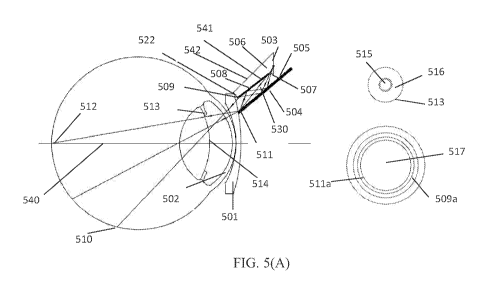
[0082] FIG. 5(A) schematically illustrates a light conditioning element
employed in
various embodiments of the eye imaging apparatus. To obtain high quality
images, proper
illumination is provided through the proper portion of the natural opening of
the eye while
avoiding the imaging path. In particular, illumination is provided through the
peripheral regions
of the eye pupil. This approach reduces backscatter from the central portions
of the pupil, which
would degrade the image of the retina obtained by light reflected from the
retina also passing
through the pupil. Since the eye is a complicated biological organ with its
own special optical
systems, the scattering and reflection from the eye in combination with its
small aperture cause
significant difficulties in obtaining a high quality image. In particular, the
reflection and
scattering from the eye cause glare and haze, which obscures the images
acquired by an eye
imaging apparatus. Thus the images from the posterior segment of the eye with
a wide field of
view often exhibit a layer of strong haze or glare. This problem is especially
acute for the
patients with dark pigmentation in the eyes. Providing illumination through
certain regions of
the eye as described herein, however, can reduce this backscatter and
reflection and the resultant
haze and glare.
[0083] The light may be emitted from a light source (not shown in FIG. 5(A))
and
injected into an optical light conditioning element 506 positioned behind the
peripheral portion
509 of the optical window 501. FIG. 5(C) schematically illustrates a
perspective view of the
light conditioning element. The light conditioning element 506 has a hollow
ring shaped body
that is configured to be disposed about or around the imaging lens 504. In
particular, the ring
33
CA 02909607 2015-10-15
WO 2014/149481 PCT/US2014/018800
shaped body has an open region in which the imaging lens 504 or a portion
thereof may be
disposed. The light conditioning element is configured to provide a channel
for light to
propagate around the outside of the imaging lens 504 to the eye. The light
conditioning element
has a central axis 540, a front end and a back end with corresponding front
surface 522 and back
surface 503. The light conditioning element also has inner and outer side
surfaces. The inner
side surface 508 is closest to the imaging lens 504 and defines the open inner
region in which the
imaging lens 504 is disposed. In various embodiments, such as shown in FIG.
5(A) and 5(D),
the inner side surface 508 comprises a multi-segment surface. In some
embodiments, the outer
side surface comprises a multi-segment surface. Different portions or segments
of the multi-
segment surface have different features such as different shapes. In some
embodiments different
segments have different curvatures and/or angles of inclination. The different
segments may also
have different textures, coatings thereon, or comprise different material.
In certain,
embodiments, however, the different segments have different shapes to reflect
and/or refract
light incident thereon differently, for example, into different directions.
[0084] As illustrated in FIG. 5(C), the body of light conditioning element may
comprise
a hollow truncated cone-shaped solid structure comprising of solid optically
transmissive or
transparent material. However, in certain embodiments the light conditioning
element comprises
opaque material. Accordingly, the light conditioning element may comprise
glass, plastic,
ceramic, metal or combinations thereof. Other materials may also be employed.
This shape may
be characterized as a hollow and ring-shaped and frusto-conical. The front
surface and the back
surface as well as cross sections orthogonal to the length are in the shape of
a circular ring. The
back surface has a larger lateral extent, e.g., inner and outer radii than the
front surface. FIG.
34
CA 02909607 2015-10-15
WO 2014/149481 PCT/US2014/018800
5(D) illustrates a cross-section view of the light condition element in some
other embodiments.
Although FIG. 5(A) and FIG. 5(D) illustrate the cross-section view of the
light conditioning
element in certain embodiments, the light conditioning element can be
rotationally symmetric
about the central axis 540 of the light conditioning element. In various
embodiments, each
segment of the multi-segment surface is annular and symmetric about the
central axis. In various
embodiments, the light condition element comprises a hollow rotational
symmetric ring, where
the inner surface of the ring comprises different segments instead of one
smooth surface.
[0085] As discussed above, at least one of the surfaces of the light
conditioning element
comprises a multi-segment surface having multiple reflective and/or refractive
segments. The
different segments in the multi-segment surface may have different
orientations, different shapes,
different coatings, or any other different configurations. In some
embodiments, the size of the
segments in the multi-segment surface varies between 0.05 mm or 0.1 mm to 1 mm
or 2 mm
along a direction of the central axis. It is also possible for the size of the
segments to be other
values. In some embodiments, the total number of segments in one light
conditioning element is
greater than 2, but less than 10, or 20. Other number of segments is also
possible. In various
embodiments, the majority of the segments comprise reflective segments (e.g.,
having a
reflectivity of at least 80%, 90%, 95%, 9-0//0,
or 100% and ranged therebetween) that reflect light
from the light sources to the eye. In various embodiments, the multi-segment
surface comprises a
substantially specularly reflective surface. Accordingly, in various
embodiments the multi-
segment surface does not comprise a microstructured refractive diffuser. The
mutiple reflective
surface segments are configured to provide precise directional control of
light, thus in various
embodiments the light conditioning element is configured to have a higher
energy efficiency
CA 02909607 2015-10-15
WO 2014/149481 PCT/US2014/018800
than a refractive diffuser. In certain embodiments, for example, the
efficiency of the light
conditioning element is 50%, 60%, 70% or higher or ranged therebetween.
[0086] The light conditioning element may distribute light received from the
light source
into different portions as a result of the different segments in the multi-
segment reflective and
refractive surface. In some embodiments, light from the light source that is
reflected from the
multi-segment light conditioning element is distributed the light into
different portions by total
internal reflection and possibly refraction of the multi-segment surface. In
some embodiments,
the light conditioning element distributes the light from the light source
into different portions
for example by total internal reflection and refraction of the multi-segment
surface. The light
conditioning element may provide a light channel 530 for propagation of light.
In various
embodiments such as shown in FIGS. 5(A) and (D), the light channel 530 is
formed by the an
inner surface 508 of the light conditioning element and an outer surface or
sidewall 505 of the
imaging lens 504. In some embodiments, this hollow external channel 530 is
configured to
receive light from the light source and direct the light to the eye. The light
channel 530 may be
considered an external light channel because this channel is formed in an open
space between the
inner surface 508 of the body of the light conditioning element and the side
surface of the
imaging lens 504. In other embodiments, the light channel may be formed
between the two side
surfaces of the body of the light conditioning element and be referred to as
an internal light
channel. In either case, at least one of the surfaces forming the channel may
comprise a multi-
segment surface. Such a multi-segment surface may distribute the light into
the eye in the
desired manner. Various embodiments include both an external light channel and
an internal
light channel.
36
CA 02909607 2015-10-15
WO 2014/149481 PCT/US2014/018800
[0087] In the embodiment shown in FIG. 5(A) and 5(D), the light conditioning
element is
configured to direct a first portion of light from the inner edge of the light
channel to a first area
of a retina of the eye including an optical axis of the optical imaging
system. In various
embodiments, the first area comprises one-third of the field of view of the
optical imaging
system. When the optical axis of the optical imaging system is aligned with
the optical axis of
the eye, the first area is the central area of the retina of the eye. In
various embodiments, the light
conditioning element is configured to direct more than 50%, 60%, 70% and 80%
of the light
exiting from the inner edge of the light channel to the first area of the
retina. The light
conditioning element is also configured to direct a second portion of light
from the outer edge of
the light channel to a second area of a retina of the eye away from the
optical axis and on an
opposite side of the optical axis from the outer edge of the light channel
from which the light is
ejected. The second area is farther from the optical axis than two-third of
the field of view of the
imaging system. When the optical axis of the optical imaging system is aligned
with the optical
axis of the eye, the second area is the peripheral area of the retina. In
various embodiments, the
light conditioning element is configured to direct more than 50%, 60% and 70%
of 1 the ight
exiting from the outer edge of the light channel to the second area of the
retina. In various
embodiments, the first portion of light forms an angle with the optical axis
of the optical imaging
system from + 10 degree to -30 degrees, and the second portion of light forms
an angle with the
optical axis from -30 degree to -90 degrees. In this case, the plus degree
corresponds to light
traveling upwardly from the optical axis shown in FIG. 5(A), and the minus
degree corresponds
to light travels downwardly from the optical axis. In various embodiments, the
direction of the
optical axis of the optical window is the same as the central axis 540 of the
hollow cone-shaped
37
CA 02909607 2015-10-15
WO 2014/149481 PCT/US2014/018800
solid structure and the two axes may be aligned in certain embodiments. In
various
embodiments, the light conditioning element is configured to direct more than
50%, 60%, 70%
and 80% of the light exiting from the inner edge of the light channel to
propagate with a first
angle between +10 degree to -30 degree with respect to an optical axis of the
optical imaging
system. In various embodiments, the light conditioning element is configured
to direct more than
50%, 60%, and 70% of the light exiting from the outer edge of the light
channel with a second
angle between -30 degree to -90 degree with respect to the optical axis.
[0088] As illustrated by FIG. 5(A), in various embodiments, the light
conditioning
element is configured to direct light outside an imaging path of the optical
imaging system at the
cornea and optical window. As a result, less backscatter is generated from the
cornea and optical
window that is in the imaging path. The image of the retina relayed to the
sensor therefore has
reduced haze and glare.
[0089] Also as shown in FIG. 5(A) and 5(D), in various embodiments, the eye
imaging
apparatus may include a hollow external light channel 530 formed between the
multi-segment
surface 508 of the light conditioning element 506 and the side surface of the
imaging lens 504.
The light conditioning element 506 may include an optical reflective (and
potentially refractive)
multi-segment surface which splits the light from the light source into
different portions, by
reflection, e.g. total internal reflection, (and potentially refraction) of
its multi-segment surface.
The multi-segment surface 508 may be suspended with proper space from the side
surface of the
imaging lens 504 to form an external light channel 530. In certain embodiments
the inner
surface of the light conditioning element and the outer surface of the imaging
lens are spaced
apart by less than or equal to 3.0 mm, 2.5 mm, 2.0 mm, 01.5 mm, 1.0 mm or 0.5
mm and larger
38
CA 02909607 2015-10-15
WO 2014/149481 PCT/US2014/018800
than zero or ranges therebetween, such as for example, between 3.0 and 2.0 mm
or between 2.5
mm and 1.5 mm, etc. in certain embodiments of the invention. Separations
outside these ranges
are also possible. In various embodiments, the side surface of the imaging
lens 504 comprises a
first layer or coating of an optically absorptive material and a second layer
or coating of an
optically reflective material 505 on the top of the absorptive coating. Such
multilayer coating
produces strong absorption to the stray light within the imaging lens 504,
while reflecting
illumination light from another side of the coating. However, other
configurations are possible.
[0090] Accordingly, with continued reference to FIGS. 5(A) and 5(D), in
various
embodiments, light is injected into the rear portion of the light channel
farther from the
transparent window. This light propagates through the light channel possibly
reflecting from the
coated sidewalls of the imaging lens and the multi-segmented inner surface of
the light
conditioning element. Light in the light channel may propagate to the forward
portion of the
light channel, which is closer to the transparent window and exit the light
channel.
[0091] In various embodiments, after multiple reflections (and possibly
refraction, for
example, at the transmissive segment 507), a portion of the light is
propagated through the outer
edge 509 of the external light channel (see, e.g., 5(D)), the optical window
501 and the cornea
502, and onto a second area 510 of a retina of the eye away from the optical
axis and on an
opposite side of the optical axis from the outer edge of the light channel.
The second area 510 is
farther from the optical axis than two-third of the field of view of the
imaging system. When the
eye is aligned with the optical axis of the optical imaging system, the second
area 510 is the
peripheral area of the retina. This light exits the channel after reflecting
from the inner surface of
the light conditioning element. For example, the last reflection prior to
exiting the light channel
39
CA 02909607 2015-10-15
WO 2014/149481 PCT/US2014/018800
is from the inner surface of the light conditioning element. The portion of
light 509a emitted
from the outer edge of the light channel may be directed at -30 to -90 degree
with respect to the
optical axis of the optical window and/or the central axis 540 of the light
conditioning element.
In various embodiments, most of the light from the outer edge of the light
channel, for example
50%, 60%, 70%, 80%, 90%, 95% or more of the light or ranges therebetween, is
directed into the
peripheral portion, such as between -30 to -90 degree with respect to the
optical axis of the
optical window and/or the central axis 540 of the light conditioning element.
[0092] Another portion of the light exits the light channel at its inner edge
511 and is
transmitted through the optical window 501, the cornea 502 and is incident on
the first area 512
of a retina of the eye including an optical axis of the optical imaging
system. The first area
comprises one-third of the field of view of the optical imaging system. In
some embodiments
when the eye is aligned with the optical axis of the optical imaging system,
the first area 512 is
the central portion of the retina. This light exits the channel after
reflecting from the outer
surface of the imaging lens. For example, the last reflection prior to exiting
the light channel is
from the outer sidewall surface of the imaging lens. In various embodiments,
the portion of light
emitted from the inner ring edge of the light channel may be directed at +10
degree to -30 degree
with respect to the optical axis. In various embodiments, most of the light
from the inner edge
511 of the light channel, for example 50%, 60%, 70%, 80%, 90%, 95% or more of
the light or
ranges therebetween, is directed into the central portion, such as between +10
degree to -30
degree with respect to the optical axis.
[0093] As shown in FIG. 5(A), in various embodiments the design of the multi-
segment
surface as well as the location of the inner edge of the light channel 511 is
such that the light
CA 02909607 2015-10-15
WO 2014/149481 PCT/US2014/018800
emitted from this area is not blocked by the edge of the iris 513 of the eye,
which may or may
not be dilated during examination. Additionally, in various embodiments, the
multi-segment
surface and the light conditioning element are configured such that this light
passes through the
pupil of the eye more at peripheral locations of the pupil than at central
locations of the pupil. In
some embodiments, for example, most of the light from the light conditioning
element does not
pass through the eye pupil within an area corresponding to the optical imaging
path so as to
reduce the likelihood of backscatter of incident illumination into the optical
imaging path. In
some embodiments this amount of light is more than 85%, 90%, or 95% or values
therebetween.
In many cases, the eye will be dilated using medication during the eye
examination. In such
cases, the pupil may be 6 to 8 mm for newborn babies, possibly 4 mm for
premature babies or 5
mm for children. In contrast, the entrance pupil of the optical imaging system
is about 1 to 2 mm
in various embodiments. Accordingly, in certain embodiments most of the light
from the light
conditioning element propagates through the eye pupil or past the entrance
pupil of the optical
imaging system a distance of at least 2 mm or 2.5 mm to 3 mm or 3.5 mm from
the optical axis
of the eye imaging system or central axis of the light conditioning element.
In some
embodiments, this amount of light is more than 80%, 90%, 95%, 97%, --
vv% or values
therebetween. Accordingly, this illumination light propagates into the eye at
locations well
outside the entrance pupil of the imaging system (which might be 1 to 2 mm in
diameter) and
only a negligible amount, if any, passes through the entrance pupil of the
optical imaging system
toward the retina. To further illustrate the illumination arrangement, a front
view of the optical
window 501 is provided as one insert in FIG. 5(A), where the light from the
inner edge of the
light channel forms a light ring 511a and the light from the outer edge forms
a larger light ring
41
CA 02909607 2015-10-15
WO 2014/149481 PCT/US2014/018800
509a. The central portion 517 of the optical window 501 is reserved as the
optical path for the
light returning from the retina as the imaging light. In order to demonstrate
the lighting
condition on the optical window, the light intensity (I) profile on the
optical window is
schematically shown in FIG. 5(B). As shown in FIG. 5(A) and FIG. 5(B), the
illumination path
and the imaging path are essentially separated at the optical window 501.
[0094] As discussed above, in some embodiments, the optical imaging system
forms an
entrance pupil near the crystalline lens of the eye. A front view of the
anterior surface of the
crystalline lens is also shown in the other insert of FIG. 5(A), where the
entrance pupil 515 is
located near the center of the iris 513. The illumination light from both the
outer and inner edges
of the light channel 509, 511 falls on the area 516 which is outside of the
entrance pupil 515 of
the optical imaging system, and does not fall onto a circular area on the
cornea or at the optical
window (e.g., the front surface thereof closest to the eye) and entrance pupil
located near an
optical axis of the optical window. Accordingly in various embodiments most of
the light (e.g. a
value greater than 50%) from the light conditioning element does not fall
within the entrance
pupil of the imaging system as this light propagates to the retina. In some
embodiments, this
value is at least 70%, 80%, 85%, 900,/0,
or values therebetween. Similarly, in various
embodiments most of the light (e.g. a value greater than 50%) from the light
conditioning
element does not fall within the optical path of imaging system at the cornea
or optical window
(e.g., the front surface thereof closest to the eye) as this light propagates
to the retina. In some
embodiments, this value is at least 70%, 80%, 85%, 900//0 ,
or values therebetween. In order to
demonstrate the lighting condition on the anterior surface of the crystalline
lens, the light
intensity (I) profile of the illumination light is also schematically
illustrated in FIG. 5(B). Such
42
CA 02909607 2015-10-15
WO 2014/149481 PCT/US2014/018800
optical arrangement creates a separation between the illumination path and the
imaging path on
the cornea, optical window (e.g., the front surface thereof closest to the
eye), and an anterior
surface of the crystalline lens and in some embodiments at the entrance pupil
of the imaging
system, and reduces or prevents the reflected and scattered light from
entering the imaging path
and eventually the image sensor. As seen in FIG. 5(B), a small border area may
be created
between the illumination zone 516 and entrance pupil 515, thus further
reducing the cross talk.
The width of the border area is less than 0.5 mm. As discussed above, the
illumination light
from the inner edge 511a of the light channel is projected to the central
portion of the retina
while the light from the outer edge 509a is projected to the peripheral area.
In various
embodiments, the light from the two light rings 509a, 511a of the optical
window 501 may
produce an overlapping area for the illumination at the retina, and form a
relatively uniform
illumination condition.
[0095] As illustrated, in various embodiments, the optical window is disposed
forward
the imaging lens and forward the light conditioning element. In certain
embodiments, the optical
window may be dropped in from inside the housing during the assembly (for
example, from the
rearward direction as opposed to from the forward, eye side direction.). In
some embodiments,
the size of the optical window is such that the peripheral portions of the
optical window extend
forward and in front of the light conditioning element. Light from the light
conditioning element
directed toward the eye may be transmitted through the peripheral portions of
the optical window
to the eye in various such embodiments. In certain embodiments, the size of
the optical window
is smaller and light from the light conditioning element directed toward the
eye is not transmitted
through the peripheral portions of the optical window to the eye.
43
CA 02909607 2015-10-15
WO 2014/149481 PCT/US2014/018800
[0096] FIG. 5(D) schematically illustrates a cross-sectional view of another
embodiment
of the light conditioning element depicting the external light channel formed
by the inner surface
of the light conditioning element, which is shown as a multi-segment surface,
and the outer
sidewall of the imaging lens. The hollow truncated cone shaped device 506 may
comprise
optically transmissive or transparent material. Some portion of its surfaces
may be optically
polished. In some embodiments, the surface 507 may be left uncoated or coated
with optical
transmission enhanced coating and may potentially redirect light by
refraction. The multiple
segments 519, 520, 521, and 522 of the surface 508 may be coated with
optically reflective
coating. The segment 521 of the surface may be in the shape of a spherical or
non-spherical
curved surface as may be the other segments in different embodiments. The
light from the light
source enters the external light channel formed between the light conditioning
element 506 and
reflective surface 505 of the imaging lens 504. Some portion of the light may
be blocked and
reflected by the reflective surface 519. Some portion of the light may be
reflected by the surface
505 first, then be reflected by the surface segment 520, and then be reflected
by the surface 505
the second time, eventually being emitted from the inner edge 511 of the light
channel and
projected onto the central area of the retina near the optical axis of the eye
and the imaging
system. Some portion of the light, which may be reflected by the surface 505
and then be
reflected by the surface 521, may be emitted from the outer edge 509 of the
light channel and
projected onto the peripheral area of the retina across the optical axis of
the eye and the imaging
system. A portion of the light, which may be reflected by the surface 505 only
once and then
exits the light channel, may eventually be projected onto the retina between
the central area and
44
CA 02909607 2015-10-15
WO 2014/149481 PCT/US2014/018800
the peripheral area in various embodiments. Ray tracing simulations can be
used to design such
multi-segment surfaces.
[0097] FIG. 5(C) and FIG. 5(E) schematically illustrates a light conditioning
element
comprising multiple sections or pieces spaced apart, for example, by multiple
gaps. The light
conditioning element is configured to provide enhanced illumination in a
sequential illumination
method which will be discussed below. As shown in FIG. 5(E), multiple gaps 518
or barriers are
used to separate the light conditioning element into multiple sections. The
barriers could
comprise light blocking (e.g. opaque) ribs or portions inside the light
channel, or light absorbing
strips or portions in the inner surface of the light conditioning element, to
have same optical
effects. For example, the light conditioning element may include four equal
sized sections. The
separations between the sections prevent the light from entering one section
of light conditioning
element from another. These separations may comprise air gaps or may be filled
with material
such as opaque material or a combination thereof. In various embodiments, the
locations and
numbers of the sections may correspond to the numbers of light emitting
elements used in
sequential illumination method. For example, the arrangement of the light
conditioning element
shown in the FIG. 5(C) and 5(E) is configured to work with the illumination
system with 4 light
emitting elements. Although the light conditioning element is shown to have
four sections, the
light conditioning element may comprise more or less sections or pieces.
Although equal size
sections are shown in FIG. 5(E), in some embodiments, sections having unequal
size may be
used. Also, although FIG. 5(E) shows four completely separate pieces, in some
embodiments
elongate slits can separate the sections but the light conditioning element
may nevertheless
comprise a single unitary piece, the four sections being defined by slits that
do not completely
CA 02909607 2015-10-15
WO 2014/149481 PCT/US2014/018800
separate the sections into separate pieces. Similarly, various combinations
may be employed.
For example, the light conditioning element may comprise two pieces, each
having such a slit
thereby providing two separate sections per piece for a total of four
sections, and other
configurations are also possible.
[0098] The light conditioning element may take many different forms, yet still
produce
the same or similar results in various embodiments. Some embodiments of the
light conditioning
element are schematically illustrated in FIG. 6(A) and FIG. 6(B). The light
conditioning element
605 may comprise solid optically transmissive or transparent material (which
may comprise
glass or plastic) with two side surfaces, an inner surface 641 and an outer
surface 642, at least
one comprising a multi-segment surface. The light conditioning element 605
comprises a light
channel 630 formed by the two side surfaces 641, 642 of the solid optically
transparent material,
where the inner surface 641 may contact the side surface of the imaging lens.
This light channel
630 within the light conditioning element 605 may be referred to as an
internal channel. Light
from the light source travels in the internal light channel within the solid
optically transparent
material. The multi-segment surfaces may include both reflective and
refractive segments. In
certain embodiments, two segments 606 and 608 are coated with optically
reflective coating,
while the remaining segments 607 is polished and optically transmissive. If
the index of
refraction of the solid optical transparent material is sufficiently high with
respect to the
surrounding medium or media, the reflective coating on the segments 606 or 608
may not be
employed in various embodiments as light may be reflected by total internal
reflection.
Accordingly, the inner surface of the light conditioning element and the outer
surface of the
imaging lens are spaced apart by an air gap having a thickness less than or
equal to 0.3 mm, 0.2
46
CA 02909607 2015-10-15
WO 2014/149481 PCT/US2014/018800
mm, 0.15 mm, 0.1 mm, or 0.05 mm and larger than zero or ranges therebetween,
such as for
example, between 0.3 and 0.1 mm or between 0.15 mm and 0.05 mm, etc. in
certain
embodiments of the invention. Separations outside these ranges are also
possible. The outer
side surface 604 of the imaging lens may be coated with optically absorptive
material to absorb
the stray light and/or reflective material in various embodiments. Either or
both the light channel
element and imaging lens may include one or more coatings that provide
reflectivity and/or
absorption.
[0099] In various embodiments, light from the light source enters the light
conditioning
element 605 when the light source is disposed against the light conditioning
element 605 or light
is directed into the light condition element using a lens, optical fiber, or
other device. Some
portion of the light may be blocked by the edge 607 of the reflective segment
of the surface 608.
In various embodiments, the majority of the light enters the internal light
channel 630 formed by
two multi-segment surfaces 606 and 608. For example, the surface 606 may
comprise two
segments 641 and 643 of the surface. In certain embodiments, a portion of the
light, which is
reflected by surface 606 and then by the surface 608 and then the surface 606
again, exits near
the inner edge 611 of the light channel and is projected onto the first area
612 of the retina after
passing through the optical window 601 and the cornea 602. A portion of the
light, which is
reflected by the surface 606 and then by the surface 608, exits near the outer
edge 609 of the
light conditioning element 605 and is used to illuminate a second area 610 of
the retina across
the optical axis 614 of the eye and the imaging system in some embodiments. A
portion of the
light, which is reflected by reflective surface 606 only once, may be
projected onto the retinal
between the first area and the second area. In various embodiments the first
area of a retina of the
47
CA 02909607 2015-10-15
WO 2014/149481 PCT/US2014/018800
eye includes the optical axis of the optical imaging system. This first area
may comprise one-
third of the field of view of the optical imaging system. When the optical
axis of the optical
imaging system is aligned with the optical axis of the eye, the first area is
the central area of the
retina of the eye. The second area of a retina of the eye is away from the
optical axis and may be
on an opposite side of the optical axis from the outer edge of the light
channel from which the
light is ejected. The second area is farther from the optical axis than two-
third of the field of
view of the imaging system. When the optical axis of the optical imaging
system is aligned with
the optical axis of the eye, the second area is the peripheral area of the
retina. In certain
embodiments, the optical arrangement for the illumination and the imaging
paths on the cornea
and the anterior surface of the crystalline lens of the eye is similar as
shown in FIG. 5(A) and
FIG. 5(B). In some embodiments, the light conditioning element including an
internal light
channel comprises a multi-piece device that includes multiple sections (and
possibly gaps
therebetween) such as illustrated in FIG. 5(E) to provide better illumination
when a sequential
illumination method is used.
[00100] FIG. 7(A) schematically illustrates some alternative
embodiments of the
light conditioning element providing a hollow external light channel and a
solid internal light
channel. FIG 7(B) shows the close-up view of another embodiment of the light
conditioning
element 706 with multi-segment surfaces. The hollow external light channel 730
includes an
inner reflective surface 705 formed by a side surface of the imaging lens and
an outer multi-
segment surface 707, 715 and 708 on the inner surface of the optical
transparent material
forming the light conditioning element 706. The light conditioning element 706
comprises a
main body comprising optical transmissive or transparent material having an
inner multi-
48
CA 02909607 2015-10-15
WO 2014/149481 PCT/US2014/018800
segment surface 707, 715 and 708 and an outer multi-segment surface that
together forms the
internal light channel 731. In various embodiments, the inner multi-segment
surface comprises
segments of the surface 707 and 715 that are coated with a reflective coating
such that the
surfaces are reflective from both sides. Reflective coating may be employed in
some
embodiments when the index of refraction of the light conditioning element is
low such that the
total internal refraction is not sufficient. Reflective coating could also be
employed when the
refractive index is high. Additionally, in some embodiments the light
conditioning element or
portions thereof are coated with absorbing material to reduce stray light.
In certain
embodiments, the absorptive coating comprises epoxy with an index of
refraction similar to that
of the light conditioning element and with an added black absorptive dye. The
remaining
segments of the multi-segment surfaces are polished optically clear. The side
surface of the
imaging lens has a first layer of optically absorptive material 704 and a
second layer of an
optically reflective coating 705 thereon. The absorptive coating 704 is used
to absorb the stray
light inside the imaging lens while the reflective coating 705 is used to
direct the light
propagating within the external light channel 730.
[00101]
After entering the light conditioning element 706, some portion of the
light from the light source passes through the refractive segment 708 of the
light conditioning
element 706 and is reflected multiple times by two reflective surfaces 705 and
707. In various
embodiments, a portion of the light is reflected by the coated outer sidewall
surface 705 on the
imaging lens first, then reflected by the inner multi-segment surface 707 of
the light conditioning
element, and then reflected by the coated outer sidewall surface 705 of the
imaging lens again,
exits near the inner edge 711 of the external light channel 730 and is
eventually projected on to
49
CA 02909607 2015-10-15
WO 2014/149481 PCT/US2014/018800
the first area 712 of the retina. Another portion of the light (not shown),
which is reflected by
the coated outer sidewall surface 705 of imaging lens only once, exits the
external light channel
730 and is projected to the retina between the first area 712 and the second
area 710. As in
various embodiments, a portion of the light, which enters the internal light
channel 731 of the
light conditioning element 706 from the light source, is split into two parts.
As shown in FIG.
7(A), a portion of light may be reflected by the inner surface 707 of the
light conditioning
element 706 before exiting the outer edge 709, while another portion of the
light may directly
exit the device 706 at the outer edge 709 of the light conditioning element
706 without reflection
from the sidewalls thereof. Light exiting from the outer edge 709 as
illustrated by rays in FIG.
7(A) may be directed toward the second area 710 of the retina. The first area
712 of a retina of
the eye includes an optical axis of the optical imaging system. The first area
712 comprises one-
third of the field of view of the optical imaging system. When the optical
axis 714 of the optical
imaging system is aligned with the optical axis of the eye, the first area is
the central area of the
retina of the eye. The second area 710 of a retina of the eye is away from the
optical axis 714
and on an opposite side of the optical axis from the outer edge of the light
channel from which
the light is ejected. The second area 710 is farther from the optical axis 714
than two-third of the
field of view of the imaging system. When the optical axis 714 of the optical
imaging system is
aligned with the optical axis of the eye, the second area is the peripheral
area of the retina. The
optical arrangement for the illumination and imaging paths on the optical
window 701 and
crystalline lens of the eye is similar as shown in FIG. 5(A) and FIG. 5(B). In
some
embodiments, the light conditioning element may comprise be a multiple pieces
device, as
shown in FIG. 5(E), comprising multiple section and multiple separations
(e.g., air or material
CA 02909607 2015-10-15
WO 2014/149481 PCT/US2014/018800
filed gaps) therebetween to sequentially provide different illumination
patterns on the retina
when a sequential illumination method is employed.
[00102] Various embodiments discussed above disclose a method of
imaging an
eye. The method comprises activating a light source to illuminate an eye,
conditioning the light
from the light source by a light conditioning element having at least one
multi-segment surface
and directing the conditioned light into the eye and onto the retina thereof,
imaging the eye
through an optical imaging system using light reflected from the retina, and
receiving an image
of the eye formed by the optical imaging system on an image sensor. The light
conditioning
element with a multi-segment surface is configured to receive light from the
light source and
direct light to the eye in an illumination pattern that, in various
embodiments provide for
illumination of peripheral sections of the retina. In some embodiments, the
light conditioning
element splits the light from the light source into different portions by
reflection (e.g. total
internal reflection) from and/or refraction caused by the multi-segment
surface. The light
conditioning element may be configured to direct a first portion of light from
an inner edge of
the light channel to a central area of a retina near an optical axis of the
eye imaging apparatus,
and direct a second portion of light from an outer edge of the light channel
to a peripheral area of
the retina away from the optical axis. To overcome the problems of scattering
from the cornea
and the anterior surface of the crystalline lens, the light conditioning
element with a multi-
segment surface may be configured to direct the light such that the light
primarily falls outside
the imaging path of the optical imaging system at the cornea and the anterior
surface of a
crystalline lens of the eye.
51
CA 02909607 2015-10-15
WO 2014/149481 PCT/US2014/018800
[00103] A variety of different types of optical windows may be used.
As
illustrated in FIGS. 7(A), for example, the optical window has an open central
aperture through
which a front end portion of the imaging lens fits into. The optical window
comprises annular or
ring-shaped transmissive or transparent body. Light rays from the conditioning
element pass
through the annular body of the window. Light returned from the retina passes
through the open
central aperture into the imaging lens. The body of the optical window has
front and rear curved
surfaces. The front curved surface is concave and has a curvature to match the
curvature of an
eye, such as a human eye, so as to fit on the surface of the cornea. The rear
surface, which is on
the opposite side and farther from the eye, has a convex surface, although in
other embodiments
other shapes surfaces may be employed for either or both the front and rear
surface of the optical
window.
[00104] Although specific designs for the frontal optical window are
shown in
FIG. 5(A), FIG. 5(B), FIG. 6(A) and FIG. 7(A), the light conditioning element
and the related
illumination system discussed in each embodiment may be used in combination
with other types
of frontal optical windows.
[00105] FIG. 8 schematically illustrates one embodiment of the eye
imaging
apparatus using light emitting elements as the light sources. The light source
of the eye imaging
apparatus may emit light in the visible spectrum, IR spectrum, near IR
spectrum and/or UV
spectrum. In some embodiments, the light source may include a plurality of
light emitting
elements. The light emitting elements may include solid state light emitters
such as light
emitting diodes and/or any other elements that are capable of emitting light.
The light emitting
elements may be compact, highly efficient and driven by low voltage. The light
sources 803
52
CA 02909607 2015-10-15
WO 2014/149481 PCT/US2014/018800
may be placed directly against the light conditioning element 802. The light
sources 803 may
include the light emitting elements and the heat sink which is used to
disperse the heat generated
by the solid state emitting devices. The light from the light sources is
directed into the posterior
segment of the eye through the light conditioning element 802 and optical
window 801 in the
manner such as discussed above. The light sources, together with the heat
sinks, are placed
outside an inner casing or shell 806 which houses the optical imaging system
including at least
part of the imaging lens 804. This casing or shell may comprise, for example,
a tube or ring.
The light sources are powered electrically through the electric wires 805
laying along the outer
surface of the casing 806. When the eye imaging apparatus comprises two
separate modules
such as a front imaging module 825 and a main module 828, which are separated
at interface
815, one or more electric connectors 807 may be used to interconnect the wires
805 in or on the
front module 825 and the wires 808 in or on the main module 828. In various
embodiments,
more sophisticated electronic drivers for the light sources 803 may be housed
in the main module
828 in the right side of FIG. 8. The removable front imaging module 825, which
is configured to
be in contact with the cornea, may be built with various kinds of light
emitting elements for a
variety of illumination requirements and applications. For example, a first
type of front imaging
module may include light emitters having a first wavelength range and a second
type of front
imaging module may include light emitters having a second wavelength range
different from the
first. The first type of front imaging module can be interchanged with the
second type of front
imaging module or vise versa, for different applications, when they are
connected with the main
body 828 with common electric connector 807. A user may select which type of
front imaging
and conveniently remove and switch out the front imaging module 825 to
another, which is
53
CA 02909607 2015-10-15
WO 2014/149481 PCT/US2014/018800
conveniently attached onto the main module 828 by the user. In certain
embodiments, the
removable front imaging modules 825 may be driven by the same standard
electronic drivers in
the main module 828 through the electrical interconnector 807. To prevent dust
from entering
housings for the optics, two optical windows 809 and 810 may be used. In
certain embodiments
comprising a single unitary housing, however, as opposed to separate front
imaging and main
modules, the electric interconnection 807 and the optical window 809, 810 may
be excluded.
[00106] In various embodiments, the location of the light sources may
be
distributed evenly to provide uniform illumination on the retina. The number
of the light sources
may vary, depending for example on the particular application. FIG. 9
schematically illustrates
two embodiments of the distribution of the light emitting elements, where a
total of 8 and 4 light
emitting elements, respectively, are used. In one embodiment, the light
emitting elements 902 is
mounted onto a heat sink 901 that comprises a ring to increase its mass and
heat dispersion
capability. There are 8 light emitting elements 902 spaced evenly on the heat
sink. The light
emitting elements may be activated sequentially or simultaneously or be
activated in any desired
order. In various embodiments, the light emitting elements are also
synchronized with the
shutter of the image sensor. Drivers and/or a controller can be employed to
control the timing of
and/or sequence of illumination. Although 4 and 8 light emitters are shown in
FIG. 9, more or
less number of light emitting elements may be used. In some embodiments,
sufficiently large
numbers of emitters are employed such that the light sources form a "linear"
line source. Such a
"linear" line source may be curved and may form a ring centered about the
optical axis of the
imaging system, for example, in some embodiment. FIG. 9 shows an embodiment
with 4 light
54
CA 02909607 2015-10-15
WO 2014/149481 PCT/US2014/018800
emitting devices 904, 905, 906, 907 at 00, 900, 180 , and 270 positioned on
an annular heat sink
903.
[00107] An eye imaging apparatus with a wide field of view that
employs
sequential illumination as described herein is capable of overcoming
scattering problems, and
thus obtaining high quality images that are essentially glare or haze free. In
some embodiments,
the eye imaging apparatus comprises a light source disposed inside the housing
wherein the light
source comprises a plurality of light emitting elements configured to
illuminate different portions
of an eye time-sequentially. The image sensor is configured to receive a
plurality of images of
the eye with a same wide field of view through the optical imaging system
while each portion of
the eye is illuminated time-sequentially. In various embodiments, the eye
imaging apparatus
further comprises an image processing unit configured to generate a set of
instructions to process
the plurality of images to create a single clear image of the eye. In some
embodiments, the eye
imaging apparatus further comprises a memory configured to temporarily store
the plurality of
images, and a computing and communication unit configured to receive and
transmit the
plurality of images. The plurality of images may be transferred to other
computing devices or
intern& based devices that include the image processing unit, which is
configured to generate a
set of instructions to process the plurality of images to create a single
clear image.
[00108] Fig. 10 schematically illustrates the example images acquired
when the
light emitting elements are activated time-sequentially and the method used to
enhance the image
quality according to various embodiments of the invention. A useful
illumination condition is
created when the light emitting elements are activated time-sequentially. For
example, in an
illumination system with 4 light emitting elements, if only one light emitting
element is
CA 02909607 2015-10-15
WO 2014/149481 PCT/US2014/018800
activated, then a first portion of the retina or the posterior segment of eye
has increased
illumination in comparison to other portions of the retina or posterior
segment of the eye. At a
later time if a second light emitting element is activated, a second portion
of the retina or the
posterior segment of eye has increased illumination in comparison to other
portions of the retina
or posterior segment of the eye including the first portion. Likewise at a
later time if a third light
emitting element is activated, a third portion of the retina or the posterior
segment of eye has
increased illumination in comparison to other portions of the retina or
posterior segment of the
eye including the first and second portions. Again, at a later time if a
fourth light emitting
element is activated, a fourth portion of the retina or the posterior segment
of eye has increased
illumination in comparison to other portions of the retina or posterior
segment of the eye
including the first, second, and third portions. In this example, where the
retina is divided into
four such sections, each of the four portions may be about 25% of the retina.
However, in other
embodiments the portion with increased illumination may be less than 50%, 40%
or 30% but
larger than 1%, 2%, 5%, 10% or 20% of the eye. In some embodiments, this
portion is between
20-30%. Other values outside these ranges are also possible.
[00109] In various embodiments, this portion is on average
illuminated more than
other portions of the eye and has an average intensity greater than that of
remaining portion or
portions of the retina or posterior segment of the eye. Accordingly, only a
portion of the
example image 1001 acquired by the eye image apparatus is shown as having
increased
illumination in FIG. 10. In the example image 1001, the shaded area which is a
bit larger than
one quarter 1005 of the image has increased illuminated, while on average
remaining quarters
1002, 1003 and 1004 are as well illuminated less. However, due to the unique
scattering
56
CA 02909607 2015-10-15
WO 2014/149481 PCT/US2014/018800
characteristic of the eye, the scattered light by the eye may show up mostly
in the oppositely
situated quarter 1003 in the form of haze or glare, leaving a clear portion in
the primarily
illuminated quarter 1005. The clear portion is essentially glare or haze free,
or only has
negligible glare or haze. Accordingly the quarter 1005, the clear portion, has
substantially less
glare or haze than the other portion. The brightness of the illuminated area
often gradually
decreases toward its boundary area 1006, while the brightness of image in the
quarter 1005 is
relatively uniform and with proper light exposure for the image sensor.
[00110]
Accordingly, in various embodiments, the first portion (approximately a
quarter) 1005 of the retina or posterior segment is illuminated, for example,
by providing light
from one of the light emitting elements while the other light emitters remain
unactivated.
Subsequently, another one of the light emitting elements is activated. As the
next light emitting
element is activated, the illuminated area is moved to be centered on another
portion such as
another quarter 1002 of the retina or posterior segment. Another image is
captured. Next a third
portion, for example, quarter, 1003 is illuminated by activating another of
the light emitting
elements. Finally, a fourth portion or quarter 1004 is illuminated by
activating another of the
light emitters and another image is capture. In such an example, each of the
emitters is activated
while the others remains unactivated. When all of the 4 light emitting
elements are activated
time-sequentially, 4 images with different quarters having increased
brightness and clear portions
are acquired.
[00111] The
order of sequence can vary. Additionally, although activation of
only one emitter at a time was discussed above, in certain embodiments, two
are more light
emitters are activated during the same time period. Additionally, although an
image can be
57
CA 02909607 2015-10-15
WO 2014/149481 PCT/US2014/018800
captured each time a different light source is activated, more than one image
may also be
recorded. Also, activating the light emitting element may comprise switching
the light emitter
on as compared to being off or otherwise increasing optical output therefrom
for example
significantly. Additionally, the light from the light emitting elements may be
blocked, impeded,
attenuated or redirected or otherwise modulated. In various embodiments,
however, different
portions of the retina or posterior segment are selectively illuminated more
than other portions.
The portion selected for increased illumination can be changed so as to
provide increased
illumination of the different portions at different times. Such selective
illumination can be
synchronized with the images captured at those times. Accordingly, images can
be obtained at
these different times and used to produce a composite image that has less haze
and glare. In
some embodiments, a driver and/or controller is used to activate the light
emitters, direct light
from a selected emitter or emitters and not from the others or otherwise
selectively modulate the
emitters. In some embodiments, simply more light from the selected emitter or
emitters is
provided in comparison to the other emitter. In certain embodiments shutters,
light valves,
and/or spatial light modulators are employed to control the amount of light
from each of the light
emitting elements. Although one emitter at a time was describe above as being
activated, more
than one light emitter can be activated at a time. In various embodiments,
more light is provided
by a subset of the total number of emitters so as to illuminate a portion of
the retina or posterior
segment or illuminate that portion more than one or more other portions. An
image is recorded.
Subsequently, a different subset of the total number of emitters is selected
to illuminate another
portion of the retina or posterior segment or illuminate that portion more
than others. Another
image is recorded. This process can be repeated multiple times in various
embodiments. For
58
CA 02909607 2015-10-15
WO 2014/149481 PCT/US2014/018800
example, 2, 3, 4 or more subsets may be selected at different times or for
providing the primary
illumination. Images of the eye may be obtained at the different times. These
images or at least
portions of these images may be employed to form a composite image of the eye,
for example, of
the retina and/or posterior segment. Accordingly, in various embodiments an
imaging
processing unit may be configured to generate a set of instructions to process
the plurality of
images to create a single clear image of the eye. Because the eye or the eye
imaging apparatus
may be moved slightly during the image capturing or imaging process, the
plurality of images
may not overlap precisely. The imaging processing unit may generate
instructions to precisely
align the plurality of images or portions thereof by analyzing the overlapping
areas. Each of the
plurality of images has a clear portion and an unclear portion. The clear
portion of the image is
essentially glare free or haze free, or has negligible glare or haze. The
clear portion has
substantially less glare or haze than the other portion, the unclear portion.
The unclear portion
exhibits glare or haze, which obscures the image. The imaging processing unit
may further
generate instructions to recognize the clear portion of an image in each of
the plurality of images,
remove an unclear portion and save the clear portion. The set of instructions
may further include
instructions to adjust the uniformity of the image brightness of the single
clear picture near a
border area to form a uniform brightness. The imaging processing unit is
configured to combine
the plurality of images to create the single clear image.
[00112] As shown in the example image 1001 in FIG. 10, for example,
in an
illumination system with 4 light emitting elements, when the quarter 1005 is
well illuminated,
the unclear portion of the image with glare is outside the boundary 1007. The
unclear portion
may be recognized and removed by a set of instructions from an image
processing unit.
59
CA 02909607 2015-10-15
WO 2014/149481 PCT/US2014/018800
Therefore only the clear portion of the image within the boundary 1007 is
saved. Similarly, only
the clear portion of the image within the boundary 1008 is saved when the
quarter 1002 is well
illuminated. Two additional images are acquired from the quarter 1003, 1004
and their
surrounding areas which are within the boundaries 1009 and 1010, respectively.
When all of the
4 light emitting elements are activated time-sequentially, 4 partial images
are acquired.
[00113] Because the eye or the eye imaging apparatus may be moved
slightly
during the imaging process, the features from the 4 partial images may not
overlap precisely.
The extended area from the border of each quarter may be used to allow the
proper adjustment
and re-alignment of the images as set forth by the instructions from the
imaging processing unit.
After the 4 images are aligned precisely, the brightness of the images in the
border area can be
re-adjusted to produce one single clear image with uniform brightness.
[00114] In some embodiments, in order to align the images taken time
sequentially, one or more additional images may be captured with all of the
light emitting
elements activated at the same time, in addition to the multiple images taken
time-sequentially as
described above. This image can be obtained using the same optical imaging
system having the
same field of view as was used to obtain the plurality of images obtained with
time-sequential
illumination. Although such image may be hazy or with glare, it may contain
the unique graphic
reference features, such as blood vessels, of the whole imaging area or the
entire field of view.
Using this image as a reference image to coordinate, each of the four partial
images described
above may be aligned with the reference image. The clear composite image could
then be formed
from the four images after proper adjustment of the locations.
CA 02909607 2015-10-15
WO 2014/149481 PCT/US2014/018800
[00115] Although in the example embodiment described above, a single
reference
image was obtained with all the light emitters activated to assist in
alignment of the other
images, in other embodiments less than all light emitters may be illuminated.
For example, the
light emitters for two quarters 1002, 1003 can be activated to align those
quarters. Similarly, the
light emitters for the other quarters 1004, 1005 can be activated to align
those quarters.
Additional images with less than all the light emitters can be activated to
provide further
alignment. For example, four reference images captured while illuminating
different pairs of the
four quarters may be used to align each of the four quarters and create a
complete composite
image.
[00116] Less reference images can also be used, for example, by
illuminating more
sections when capturing the reference image. In some embodiments, for example,
a first
reference image can be captured with three of the four quarters illuminated,
and a second
reference images can be captured with different three of the four quarters
illuminated.
Alignment can be provided using these first and second reference images. Other
variations are
possible. As discussed above, the number of sections illuminated and number of
light emitters
used to obtain the one or more reference images can vary.
[00117] Accordingly, one or more reference image can be employed to
align
images of sections obtained using time-sequential illumination. To generate a
reference image,
multiple sections are illuminated and an image is capture by the optical
imaging system and
sensor. This reference image will depict the sections and their positional
relationship, and will
contain reference features that can be used to align separate images of the
separate sections.
Although reference images can be obtained by illuminating all of the sections,
not all the sections
61
CA 02909607 2015-10-15
WO 2014/149481 PCT/US2014/018800
need to be illuminated at the same time to produce reference images that can
assist in alignment.
These reference images can be captured using the same optical imaging system
having the same
field of view as was used to obtain the plurality of images captured during
time-sequential
illumination. However, in alternative embodiments, reference images can be
captured by other
optical imaging systems and sensor. Additionally, reference images can be
captured with using
different fields-of-view. Other variations are possible.
[00118] An image processing unit may be utilized to process the
images as set
forth above to provide alignment. For example, the image processing unit may
identify the
reference features in the reference images to determine the positional
relationship of the sections.
The image processing unit may further align sections of images captured using
time sequential
illumination based on those reference features and the determined positional
relationship of the
sections.
[00119] In various embodiments, the rate of frequency of the time-
sequential
capturing is determined by the image capturing rate. In some embodiments, the
imaging
apparatus is configured to capture each image between 15 ms or 30 ms to 150 ms
or 200 ms.
[00120] Accordingly, a method of imaging an eye by sequential
illumination is
disclosed to obtain high quality retinal images with a wide field of view. The
method comprises
activating a plurality of light emitting elements time-sequentially to
illuminate different portions
of an eye, imaging the eye through an optical imaging system and receiving a
plurality of images
of the eye through the optical imaging system and sensor while different
portions of the eye are
illuminated time-sequentially. The images are captured by the image sensor and
processed to
create a single clear image of the eye. The method may be used to digitally
remove the unclear
62
CA 02909607 2015-10-15
WO 2014/149481 PCT/US2014/018800
sections, thus reducing or removing the haze from the plurality of images
obtained from the
sequential illumination.
[00121] The sequential illumination method discussed in the previous
paragraph
may be applied when different numbers of the light emitting elements are used.
The possible
examples include 2 elements, 3 elements, 4 elements, 6 elements, 8 elements or
even more
elements. The light emitting elements need not be individually activated. In
some embodiment,
pairs may be activated at a time. Similarly, 3, 4, or more may be activated at
a time. Other
variations are possible.
[00122] Accordingly various embodiments comprise an eye imaging
system
comprising an eye imaging apparatus such as for example shown in FIG. 1(A) and
FIG. 1(B),
and an image computing module that includes another computing device or
intern& based
device. The eye imaging apparatus may comprise a plurality of light emitting
elements, an
optical imaging system, an image sensor, memory and a computing and
communication unit. In
certain embodiments, the plurality of light emitting elements is configured to
illuminate different
portions of an eye time-sequentially. The image sensor is configured to
receive a plurality of
images of the eye with a same wide field of view through the optical imaging
system as the
different portions of the eye are illuminated time-sequentially. In various,
although not all
embodiments, the memory is configured to at least temporarily store the
plurality of images
captured by the image sensor. The computing and communication unit may be
configured to
receive and transmit the plurality of images. The eye imaging apparatus may
further include a
touch screen display to display the images. The image computing module may be
configured to
receive the plurality of images from and exchange data with the eye imaging
apparatus. The
63
CA 02909607 2015-10-15
WO 2014/149481 PCT/US2014/018800
image computing module may further include an image processing unit, which is
configured to
generate a set of instructions to process the plurality of images to create a
single clear image of
the eye. Other embodiments are also possible.
[00123] In some embodiments of the eye imaging apparatus, as
schematically
illustrated in FIG. 11, one or more optical fibers 1105 are used to guide the
light from the light
emitting element(s) 1107 to the light conditioning element 1102. In various
embodiments,
optical fiber bundles are used. The construction for the rest of the imaging
apparatus is similar to
the one shown in FIG. 8. When the eye imaging apparatus comprises two separate
modules such
as a front imaging module and a main module, which are separated at interface
1109, one or
more electric connectors 1115 may be used to interconnect the wires 1108 in or
on the front
module and the wires 1110 in or on the main module. To prevent dust from
entering the
housings and depositing on the optics, two optical windows 1111 and 1112 are
used to seal off
the housings. If a single piece construction is required, then the electric
interconnection 1115 and
the optical windows 1111, 1112 can be excluded.
[00124] FIG. 12 schematically illustrates two embodiments of fiber
optic couplers
configured to couple light from the light emitting elements to the optical
fiber. The optical fibers
may be used to form multiple lighting elements that can be disposed against
the light
conditioning element. One example is schematically illustrated in FIG. 12,
where optical fiber
lighting elements 1202, 1203, 1204 and 1205 are incorporated into a lighting
base 1201 and
distributed evenly thereabout. The shape and size of each optical fiber
lighting element shown in
FIG. 12 is an example only and does other design can be employed. The number
of the optical
64
CA 02909607 2015-10-15
WO 2014/149481 PCT/US2014/018800
fiber lighting elements may be 4, 8 or any other number of lighting elements.
As shown,
continuous light sources, such as liner light sources, may be provided.
[00125] The lighting element such as for example lighting element
1202 shown in
FIG. 12, receive light from one light emitting element. While two examples are
shown in FIG.
12, other embodiments may be used to increase the optical coupling efficiency.
In one
embodiment, an optical coupling lens 1210 is used to collect light from the
light emitting
element 1208 and relay the light into the entrance of an optical fiber bundle
1211. The
individual optical fibers in the bundle 1211 is then spread out at the another
end of the fiber to
form the lighting element. The light emitting element often comprises a
protective dome 1209
and is mounted onto a ceramic or metal base 1207. The multiple light emitting
elements may be
mounted to a larger heat sink base 1116, as shown in FIG. 11, through their
ceramic/metal bases,
in order to increase the heat dispersion capability. The heat sink may also be
in contact with the
lens housing or casing, which is shown as 1106 in FIG. 11 of the imaging
apparatus in order to
disperse the heat. If the heat sink (ring) 1116 is built next to the
interconnection surface 1109 as
shown in FIG. 11, a pair of matching heat conducting surfaces comprising for
example copper or
other materials having good thermal conductivity may be built along the
interconnection surface
1109, and as part of extension of lens housing 1106 and lens housing 1117 in
the front and main
modules of the imaging apparatus. When the removable front imaging module is
attached to the
main module of the imaging apparatus, the two heat conducting surfaces 1106,
1117 may contact
each other, thus permitting transfer of the heat from the lighting elements to
the larger mass in
the main module. Such a design may reduce the temperature of the imaging
apparatus housing,
CA 02909607 2015-10-15
WO 2014/149481 PCT/US2014/018800
especially the housing of the removable front imaging module, which the user
may employ to
holds the imaging apparatus in various embodiments.
[00126] Also shown in FIG. 12, in some embodiments, the optical fiber
bundle
1215 is directly inserted into the dome 1214 of the light emitting element
1213. The direct
coupling may produce high efficiency, although the seal for the dome is
penetrated which may
have implications in certain situations..
[00127] In yet another embodiment shown in FIG. 13, the light
emitting element
1308 is disposed in the main module of the eye imaging apparatus. The light is
then guided to the
light conditioning element 1302 through an optical fiber bundle 1305, which
forms the new
lighting element 1303. If the front imaging module is removable, then an
optical coupler 1307
may be added to couple light from one side of interconnection 1311 to another.
In certain
embodiments, for example, two fiber bundles are aligned to each other, a first
on the main
module and a second on the front modules. The fiber bundles can be disposed so
as to have ends
that are in direct contact such that light can be coupled from the first fiber
bundle into the second
fiber bundle. The power of the lighting element 1303 is supplied through the
electric wires 1309
by the electronic drivers.
[00128] Another coupling design is schematically illustrated in FIG.
14. A light
emitting element 1407 is located in the main module of the eye imaging
apparatus, but near the
interconnection interface 1411. The light is coupled into an end of an optical
fiber bundle 1405,
which is located in the removable front imaging module of the imaging
apparatus, with the end
of the optical fiber bundle being exposed to the outside and facing the light
emitting element
1407. The optical fibers in the bundle 1405, extend along the outside of the
lens housing or
66
CA 02909607 2015-10-15
WO 2014/149481 PCT/US2014/018800
casing 1406 and are used to form the multiple lighting elements 1403. The
power of the light
emitting element 1407 may be supplied through the electric wires 1408 from the
electronic
drivers.
[00129] One embodiment of the optical coupling design is shown in
FIG. 15,
where the dash line 1506 represents the interconnection interface between the
two modules of the
imaging apparatus. In various embodiments, the light from the light emitting
element 1502 is
initially collimated by a dome lens 1503. The collimated light is coupled to
the fiber optical
bundle 1507 through a coupling lens 1504. The light emitting element has a
base 1501 that is
mounted onto a heat sink base in the main module of the imaging apparatus. The
coupling
optical lens 1504 is also mounted in the main module and can be pre-aligned
with the light
emitting element 1502. Because the optical fiber bundle 1507 is located in the
removable front
imaging module of the imaging apparatus and does not come into physical
contact with optics in
the main module, the light 1505 is projected into the end of the fiber bundle
directly through air
or via free space. Such arrangement not only increases the optical coupling
efficiency of the
light, but also reduces wear at the end of the optical fiber bundles.
[00130] The light emitting elements in various embodiments may emit
the light
with broadband spectrum or narrow band spectrum. The light may be visible to
the human eye
with a single color or broadband, for example, a white color. The light may
also be invisible to
the human eye and be, for example, in the infrared, near infrared or UV range.
All of the light
emitting elements used in one unit may emit the same kind of light or
different kinds of light.
[00131] In various embodiments, the light emitting elements emit
white color light
for color imaging applications. However, for certain applications, the light
emitting elements
67
CA 02909607 2015-10-15
WO 2014/149481 PCT/US2014/018800
may emit light in deep blue color, for example, when driven by the same
electrical power supply
system from the main module. The blue light may excite the fluorescin dye in
the blood vessels
of the eye, which in turn may emit green light. In certain embodiments, the
optical window at
the end of the removable front imaging module, such as 809 in FIG. 8, 1111in
FIG. 11, 1310 in
FIG. 13 and 1409 in FIG. 14, which is used to protect the optics from dust,
comprises an optical
blocking filter. For example, a green band pass filter may be employed. In
such embodiments,
the green emission light may be collected by the optics in the main module to
form an image of
fluoresin angiogram. The optical blocking filter reflects/absorbs the blue
light, but allows the
green and/or other emission light to be transmitted. The removable front
imaging module with
such features may be constructed as a fluoresin angiogram unit. Similarly,
another type of
angiogram imaging apparatus may be formed when the light emitting elements
emit near infrared
light and the optical blocking filter works in such spectrum too (for example,
filters out near IE
light). Accordingly, a filter that blocks the light produced by the emitters
but transmits other, for
example, longer, wavelengths, may be used to transmit fluorescent or other
emission to the
optical sensor.
[00132] Because the optical window in the eye imaging apparatus is
configured to
be in contact with the patients, adequate sealing around the peripheral joint
between the optical
window and the housing can assist in reducing or preventing cross-
contamination by the bacteria.
FIG. 16 schematically illustrates one embodiment of a hermetically sealed eye
imaging apparatus
where the optical window may be dropped in from inside the housing during the
assembly
process. The optical window 1601 is in contact with the cornea 1602 of eye,
but separated from
the imaging lens 1603 with a small gap 1606. In various embodiments, the
surfaces of the
68
CA 02909607 2015-10-15
WO 2014/149481 PCT/US2014/018800
optical window 1601 and the imaging lens 1603 on both sides of the gap 1606
may have the
same or similar radius of curvature. The gap 1606 may be filled with air or
other optically
transparent but mechanically elastic materials during the subsequent
assembling process. Optical
coatings may be applied to the optical surfaces on the both sides of the gap
1606 to reduce the
optical reflectivity. The gap 1606 not only allows application of more
sophisticated sealing
technologies, but also adds a space for compensating for thermal expansion. In
various
embodiments, the gap 1606 between the optical window and the imaging lens
adjacent thereto,
for example, at the optical axis of the imaging lens, is between about 0.5 mm
and 0.001mm, or
0.3 mm and 0.001 mm although values outside this range are possible. The
periphery of the
imaging lens 1603 may be a conical or frusto-conical shape and may be coated
with optically
absorptive material 1607. The absorption spectrum of the optically absorptive
material 1607
may be in the visible spectral range of the eye although the absorption
spectrum may also extend
into the invisible spectra. The absorptive coating 1607 may not only prevent
the light from
entering the imaging lens from outside, but also absorb the stray light from
the eye when this
light enters the imaging lens 1603 along with the light used for forming an
image. A small
opaque absorption ring 1608 may be added to the edge of the gap 1606 to
prevent the light from
entering the gap from the sides. The edge of the gap 1606 may also be simply
filled with a small
amount of optically absorptive material. The optical window 1601 is aligned
with the rest of
imaging optics with the help of the apparatus housing 1640, while the proper
gap 1606 is
maintained as a result.
[00133] The housing 1640 of the eye imaging apparatus comprise metal
or other
materials. The housing 1640 has a front end 1630 extends around the edge of
the optical window
69
CA 02909607 2015-10-15
WO 2014/149481 PCT/US2014/018800
1601. The front end 1630 has a smooth front edge 1609 to prevent injury to the
patients during
the operation and to protect the optical window 1601 from scratching by hard
foreign objects. A
small flat surface 1610, in the form of a circular ring, may be disposed on
the front peripheral
area of the optical window 1601. This small flat surface 1610 may be near
and/or extend from
the side of the optical window 1601 to or near to the edge of the front
concave surface of the
optical window 1601. The front end 1630 of the housing 1640 is shaped and
sized to fit with the
profile of the optical window 1601 at the edge of the optical window, as shown
in FIG. 16, and
in various embodiments allows for various gaps between the housing 1640 and
the optical
window 1601. In various embodiments, an inner side surface 1650 of the housing
1640
comprises an alignment edge 1611 and a reservoir edge 1612 at the front end
1630. The optical
window is separated from the alignment edge with a first gap which is
horizontal and parallel to
the side surface of the optical window. In various embodiments, the width of
the first gap is
between 0.3 mm and 0.01 mm or 0.2 mm and 0.01 mm. The alignment edge 1611
assists
precision alignment of the optical window 1601 with the housing 1604 in
directions normal to
the optical axis. In various embodiments, the housing has an opening for
fitting the optical
window therein from the right hand side, as shown in FIG. 16, and for
providing a gap, the first
gap, between the optical window and the housing.
[00134] In some embodiments, the housing 1640 comprises a distal
section 1604,
which is a small housing, and a proximal section 1605, which is the apparatus
housing. The
proximal section comprise metal or other materials. The distal section, which
may be a small
housing, comprising the same or different metal material, in some embodiments,
is connected to
the proximal section 1605 by a bond. When the small housing 1604 is aligned
with the apparatus
CA 02909607 2015-10-15
WO 2014/149481 PCT/US2014/018800
housing 1605, then the optical window 1601, may, for example, be properly
aligned with the
optical axis of the imaging lens and imaging system. In various embodiments,
the first gap
provides for flow of hermetical sealing material as is discussed below. The
opening bounded by
the alignment edge of the housing is sufficiently large such that after the
optical window is
centered and aligned, the small first gap remains disposed between the housing
and the window
to allow for hermetic sealing material. To assist in placement of the optical
window 1601
precisely along the optical axis and maintain a proper gap 1606, a small
vertical surface is made
in the frontal end 1630 of housing 1604, which creates a vertical gap 1633
between the housing
and the small flat surface 1610 on the front peripheral area of the optical
window 1601. In
various embodiments, the width of the vertical gap is about between 0.3 mm and
0.01 mm or 0.2
mm and 0.01 mm. This vertical gap 1633 may permit the flow of hermetic
material between
housing and the small flat surface 1610 on the front peripheral area of the
optical window 1601.
[00135] The optical window is also separated from the reservoir edge
1612 with a
second gap. In various embodiments, the width of the second gap is about
between 1.0 mm and
0.3 mm or 0.5 mm and 0.3 mm. The second gap may be larger than the first gap
and configured
to be a reservoir to be filled with a hermetic sealing material 1613. In
various embodiments,
when the hermetic sealing materials 1613 is melted under high temperature, the
hermetic sealing
material under the effect of gravity and surface tension force, also fills the
smaller gaps, such as
the first gap as well as the vertical gap between housing and the small flat
surface 1610 on the
front peripheral area of the optical window 1601 between the optical window
1601 and the
housing 1640 to provide an air tight seal and strong bonding. The hermetic
sealing material
comprise material such as ceramic or metal that can, for example, be melted at
very high
71
CA 02909607 2015-10-15
WO 2014/149481 PCT/US2014/018800
temperatures and be caused to form an airtight seal that remains intact even
when subjected to
autoclave temperatures such as for example 120 C, 135 C, 140 C, or
temperatures therebetween
or potentially higher.
[00136] As illustrated, the front end 1630 of the housing 1640 where
the optical
window 1601 is disposed has vertical and horizontal edges, that with the help
of an alignment
fixture during manufacture and hermetic sealing material in the vertical and
first gap, permit
horizontal and vertical alignment, positioning, and proper orientation of the
optical window in
the imaging system. In this particular case, such vertical and horizontal
edges of the housing
form a corner in which the window surrounded by hermetic sealing material
fits.
[00137] To match the thermal expansion properties of optical window
material and
the housing 1640, a special material may be used for the distal section 1604
of the housing 1640.
In some embodiments, the whole housing 1640 may be made of the same material.
In some
embodiments, different materials may be used to make the housing. In various
embodiments, the
housing may comprise a distal section 1604, for example, a cap, and a proximal
section 1605.
The distal section 1604 is connected with the proximal section 1605 by a joint
section 1613. In
certain embodiments, for example, the distal section 1604, may comprise a
first material such as
titanium and the more proximal section 1605 of the housing comprises a second
material such as
aluminum. In certain embodiments, a distal section 1604 of the housing may be
welded, bonded
or otherwise connected together with a more proximal section of the housing
1605 at a joint
section 1613. In various embodiments, the distal section of the housing can be
bonded together
with special treatment, such as explosion welding, to a portion of the joint
section 1613
comprising the same material as the proximal section of the housing, the
second material. For
72
CA 02909607 2015-10-15
WO 2014/149481 PCT/US2014/018800
example, in the case where the distal section 1604 comprises titanium (first
material) and the
more proximal section comprises aluminum (second material), the joint section
1613 may
comprise the aluminum (the second material). This aluminum (second material)
in the joint
section 1613 is bonded to the titanium (first material) using, for example,
explosion bonding.
The aluminum (second material) in the joint section is then bonded to the
aluminum (second
material) in the more proximal section of the housing using for example laser
welding. Other
approaches to connecting the more distal and more proximal sections of the
housing may be
employed. In some embodiments, for example, the connection between the distal
section 1604
of the housing and the more proximal section 1605 of the housing is filled
with a hermetically
sealing material. The material for the hermetically sealing could be, e.g.,
glass, ceramic, metal or
adhesives. Such a technique may be employed, in some embodiments where the
distal section of
the housing comprises a different material than the more proximal section of
the housing. In
some embodiments, a special bonding section is introduced at the joint section
1613 in the form
of a thin ring, which comprises two different materials. The front surface of
the thin ring
comprises the first material that may be welded with the distal section 1604,
while rear surface of
the thin ring comprises the second material that is then welded with the more
proximal section
1605. The two materials (first material and second material) in the thin ring
are bonded together
with special bonding technique, such as explosion welding. In some
embodiments, the distal
section 1604 may simply be glued to the more proximal section 1605.
[00138] As illustrated in FIG. 16, as well as elsewhere (see, e.g.,
FIG. 1) in various
embodiments, the housing is tapered and reduces in size closer to where the
optical window is
disposed and where contact with the eye/cornea is made. This tapered or
sloping profile of the
73
CA 02909607 2015-10-15
WO 2014/149481 PCT/US2014/018800
housing accommodates both the larger size of the relay lens and the smaller
size of the window
and imaging lens. As discussed above, the imaging lens may be frusto-conical
and likewise be
tapered as well, with the aperture size of the imaging lens being smaller
closer to the eye than
farther from the eye. In various embodiments, as shown in FIG. 16 and
elsewhere, the bond,
weld, or joint discussed above may be included in the front end where the
housing is tapered.
[00139] In some embodiments a washer made of the same material as
that of
housing 1605 is included in the housing between the joint section 1613 and the
proximal section
1605. The thickness of the washer is adjustable and permits the length of the
housing in the
longitudinal direction to be adjusted, which in turn controls the gap 1606
ultimately.
[00140] FIG. 17 illustrates another embodiment of a hermetically
sealed eye
imaging apparatus. In this embodiment, the shape of the small housing, or the
distal section,
next to the optical window is modified from that in the embodiment shown in
FIG. 16. The gap
1721 between the alignment edge 1711 and the edge of the optical window 1701
is reduced,
which can provide both more precise optical alignment and a sufficient space
to allow the free
flowing of the hermetical sealing material from the reservoir 1713 through the
narrow gap at the
same time. The narrow vertical gap 1633 between the housing and the flat
surface 1610 on the
front peripheral area of the optical window 1601 shown in the FIG. 16 is
removed. The removal
of this narrow vertical gap 1633 and the full filling of the narrow gap 1721
between the
alignment edge 1711 and optical window 1701 with the hermetical sealing
material reduces risk
of contamination problems. If the narrow vertical gap 1633 is not fully
filled, for example the
bacteria and other contaminants may hide inside and cause cross contamination
between the
patients.
74
CA 02909607 2015-10-15
WO 2014/149481 PCT/US2014/018800
[00141] As discussed above with respect to FIG. 16, in various
embodiments, the
housing shown in FIG. 17 has an opening for fitting the optical window therein
and for providing
a gap, the first small gap, between the optical window and the housing. Having
such opening
and a gap permits the optical window to be laterally translated and aligned,
for example, using an
alignment fixture that moves the lens laterally with respect to the housing.
The optical window,
may, for example, then be properly aligned with the optical axis of the
imaging lens and imaging
system when the housing is aligned with the rest of the imaging system. . The
first gap permits
this lateral movement and alignment. Additionally, this first gap provides for
flow of hermetical
sealing material. Accordingly, the opening in the housing is sufficiently
larger such that after the
optical window is centered and aligned, the small first gap remains disposed
between the housing
and the window to allow for filling with the hermetic sealing material.
[00142] The optical window is also separated from the reservoir edge
1712 of the
housing with a second larger gap1722. The second gap 1722 may be larger than
the first gap
1721 and configured to be a reservoir to be filled with a hermetic sealing
materia11713. In
various embodiments, when the hermetic sealing materials 1713 is melted under
high
temperature, the hermetic sealing material also fills the smaller gap 1721
between housing and
the optical window 1701 to provide an air tight seal and strong bond. The
hermetic sealing
material 1713 may comprise material such as glass, ceramic or metal that can,
for example, be
melted at very high temperatures, for example, larger than 500 C and caused to
form an airtight
seal that remains intact even when subjected to autoclave temperatures such as
for example
120 C, 135 C, 140 C, or temperatures therebetween or potentially higher.
CA 02909607 2015-10-15
WO 2014/149481 PCT/US2014/018800
[00143] As discussed above, during the sealing operation, the
alignment fixture
holds the window into the center of opening of the housing where the window is
inserted and, in
certain embodiments, preserves a uniform gap around the periphery of the
window. The
alignment fixture also sets proper recess depth for the optical window by the
small flat surface
1710 in reference to the front end 1724 of the small housing 1704, along the
optical axis of the
optical window. The viscosity of the hermetic material may be controlled so
that the hermetic
material wets both the window and the housing surface next to the gap and
fills the first gap 1721
from the reservoir 1722, under the gravity and surface tension force. In
various embodiments,
the first gap 1721, which may be filled with hermetical sealing material 1713,
is less than 1 mm
or less than 0.2 mm although values outside this range are possible. In some
embodiments, the
thickness of first gap 1721 is made larger when approaching the space on the
eye side, by the
design of larger opening for the alignment edge 1711 and/or small 45 degree
chamfer at the
corner of optical window edge. As a result, when hermetic material is flowed
through the first
gap 1721, from the second gap 1722, the surface tension of the hermetic
material will limit or
stop the flow of the hermetic material into other surfaces on the eye side. In
certain
embodiments, the sealant not only seals the window, but also holds the window
in the center of
the opening of the housing.
[00144] FIG. 18 schematically illustrates another embodiment of the
hermetically
sealed eye imaging apparatus. In this embodiment, a plurality of tiny balls
1814 are disposed
with equal space around the periphery of the optical window and inside a
plurality of bores 1815.
The optical window 1801 is separated from an alignment edge 1811 of the
housing with a first
gap 1821. The optical window is also separated from a reservoir edge 1812 of
the housing with
76
CA 02909607 2015-10-15
WO 2014/149481 PCT/US2014/018800
a second larger gap1822. This gap 1822 is configured to be the reservoir for
the hermetically
sealing material 1813. The balls 1814 are disposed in bores or boreholes 1815
drilled in the
inner surface of the front end of the housing to accommodate the balls 1814.
The bores 1815
have a diameter slightly larger than the second gap 1822 in order to enlarge
the second gap 1822.
Because of the increased size of the borehole 1815, the second gap 1822 is
larger in the area
surrounding the ball than in other areas where the ball 1814 is not
positioned. The bore holes
1815 are disposed at a sufficient height such that a very narrow gap 1823 is
disposed between the
ball 1814 and the optical window 1801. This gap 1823 is beneath the ball 1814
as illustrated in
the cross-sectional shown in FIG. 18. This narrow gap 1823 beneath the ball
1814 is narrower
than the first gap 1821.
[00145] Such arrangement as describe above using balls 1814 as
spacers with a
gap between the ball 1814 and the optical window 1801 facilitates precise
alignment between the
optical window 1801 and the housing 1804. As discussed above, the housing has
an opening for
fitting the optical window therein and for providing the first and second gaps
and in particular,
the small gap 1823 between the optical window 1801 and the ball 1814 when the
ball 1814 is in
place in a borehole 1815. Having a larger opening and a gap permits the
optical window to be
laterally translated and aligned, for example, using an alignment fixture that
moves the lens
laterally with respect to the housing. The optical window 1801 may, for
example, be properly
aligned with the optical axis of the imaging lens and imaging system when the
housing is aligned
with the rest of imaging system. The small 1823 gap permits this lateral
movement and more
precise alignment.
77
CA 02909607 2015-10-15
WO 2014/149481 PCT/US2014/018800
[00146] Additionally, this small gap 1823 provides for flow of
hermetical sealing
material. Accordingly, the opening in the housing is sufficiently larger such
that after the optical
window 1801 is centered and aligned, the small gap 1823 remains disposed
between the housing
and the window 1801 to allow for hermetic sealing material 1813. A slightly
larger gap 1821
between the edge of the optical window 1801 and the alignment edge 1811 of the
housing (as
compared for example to the first gap 1711 shown in the embodiment illustrated
in FIG. 17)
makes it easier for the hermetically sealing material 1813 from the reservoir
1822 to fully fill the
gaps and space around the tiny balls 1814. As discussed above, in various
embodiments, when
the hermetic sealing materials 1813 is melted under high temperature, the
hermetic sealing
material 1813 also fills the smaller gap 1823 between balls 1814 and the
optical window 1801 to
provide an air tight seal and strong bond. The melted hermetic sealing
material also forms a
hermetic seal in portions of the larger gap 1822 elsewhere around the balls
1814 as well as where
the balls 1814 are not disposed. The hermetic sealing material 1813 comprise
material such as
glass, ceramic or metal that can, for example, be melted at very high
temperatures and caused to
form an airtight seal that remains intact even when subjected to autoclave
temperatures such as
for example 120 C, 135 C, 140 C, or temperatures therebetween or potentially
higher.
[00147] The layout with 3 and 4 balls are demonstrated in FIG. 18.
These layouts
show the arrangement of the balls, for example, as seen from the inside of the
housing. These
layouts, however, are to schematically illustrate where the balls are placed
relative to each other.
The number of the balls may vary including 3, 4, and other numbers. The spacer
may be for
example 0.5 mm in lateral extent such as diameter. Larger or smaller spacers
may be used. The
spacer, for example, may be as large as 1.0 mm and possibly 0.3 mm or smaller
or any size
78
CA 02909607 2015-10-15
WO 2014/149481 PCT/US2014/018800
between these values. Other sizes outside these ranges may also be possible.
The spacers may
comprise for example sapphire in some embodiments although other materials may
be employed.
In some embodiments, the balls may comprise the same material as the housing
1804 and/or the
optical window 1801. The balls 1814 may also comprise materials that have a
similar thermal
expansion property as the optical window 1801 and/or the housing 1804. Spacer
having shapes
other than spheres can be employed. Cylindrically shaped spacers, for example,
may be used.
Additionally, the spacing can be different than shown in FIG. 18 and need not
be evenly spaced.
[00148] In various embodiments, the diameter of the spacer, e.g., the
ball, is
selected to be slightly larger than the second gap. Therefore, when the bore
is drilled, the outer
edge of the bore extends beyond the outer edge of the second gap. Such
arrangement prevents
the balls from moving from of their location (e.g., in the bores) during the
alignment and sealing
operation. When the ball 1814 is placed in the bore 1815 and the window 1801
is inserted, a first
side of the ball and the edge of the window provide the small gap 1823 while
the second opposite
side of the ball contacts the outer wall of the bore 1815. In various
embodiments, the addition of
the balls effectively reduces the space between the window 1801 and the
housing 1804, and
allows the hermetic material 1813 to flow easily in the large gap and the
space between the balls.
Also, with the spherical shape of the ball, the width of the first gap 1823 is
widened on side
facing the reservoir 1822 than the opposite side. As the result, the material
can easily wet the
surface of the ball and surround the ball within the material when the
material is still in the fluid
state.
[00149] FIG. 19 demonstrates another embodiment of a hermetically
sealed eye
imaging apparatus where the optical window may be dropped in from the front
side (eye side)
79
CA 02909607 2015-10-15
WO 2014/149481 PCT/US2014/018800
during the assembly process. The hermetic sealing is applied between the
optical window 1901
and the housing 1904. The embodiment has similar components as the embodiment
shown in
FIG. 16. For example, the imaging lens 1903, the absorptive coating 1907, the
absorptive
material 1908 and the gap 1906 function similarly as the imaging lens 1603,
the absorptive
coating 1607, the absorptive material 1608 and the gap 1606 respectively.
Special bonding or
welding process and design can be applied to the joint section 1913 in the
embodiment shown in
FIG. 19, as the joint section 1613 shown in FIG. 16. The optical window 1901
has a small flat
surface 1910 disposed about the edge or periphery of the front concave surface
of the optical
window 1901. The use of the smooth corner 1909 at the front end of housing
1904 prevents
potential injury to the patients during the operation. The optical window 1901
is designed to be
dropped into the housing 1904 from the front side. A small alignment ring or
edge 1911 is built
into the housing 1904. The alignment ring 1911 includes a corner in which the
edge of the
optical window 1901 contacts. In various embodiments, the dimensions of the
alignment ring
1911, and in particular the shape and size of the corner of the alignment ring
1911 are
sufficiently similar to that of the edge of the optical window 1901 to provide
a tight fit
therebetween. As illustrated, the alignment ring 1911 has vertical and
horizontal edges that
permit horizontal and vertical alignment, positioning, and proper orientation
of the optical
window in the imaging system. In this particular case, such vertical and
horizontal edges of the
housing form a comer in which the window 1901 fits. Accordingly, the small
alignment ring
1911 provides more precise alignment between the two components in comparison
to an
embodiment without the alignment ring. The larger gap between the two
components is filled
with the hermetically sealing material 1912 under high temperature. Such
design not only
CA 02909607 2015-10-15
WO 2014/149481 PCT/US2014/018800
provides air tight sealing to prevent growth of the bacteria in the small gap
or cracks, but also
enables strong bonding between the optical window 1901 and the housing 1904.
An adhesive
may also be used to seal the optical window 1901 in this embodiment.
[00150] FIG. 20 schematically illustrates another embodiment of the
imaging
apparatus where an adhesive and/or a hermetically sealing material may be used
to seal the
optical window. The housing 2004 of the front module housing is constructed
with one single
piece although a multi-piece front module housing may be employed as well. The
designs for
the imaging lens 2003, the absorptive coating 2007, the absorptive material
2008 and the air gap
2006 are similar as the imaging lens 1903, the absorptive coating 1907, the
absorptive material
1908 and the gap 1906 illustrated in FIG 19. A small flat surface 2010 is
disposed about the
edge or periphery of the concave surface of the optical window 2001. An
alignment edge or ring
2011 is included in the housing 2004 to help align the optical window 2001.
Accordingly, the
alignment ring 2011 has a vertical edge that permit lateral alignment
adjustment, axial
positioning, and proper orientation of the optical window in the imaging
system. However, as
illustrated, the housing has an opening for fitting the optical window 2001
therein and for
providing a gap between the housing and optical window. As discussed above,
having a larger
opening and a gap 2012 permits the optical window to be laterally translated
and aligned, for
example, using an alignment fixture that moves the lens laterally with respect
to the housing.
The optical window may, for example, be properly aligned with the optical axis
of the imaging
lens and imaging system. The gap 2012 permits this lateral movement and
alignment.
Additionally, this gap 2012 provides for flow of sealing material.
Accordingly, the opening in
the housing is sufficiently larger such that after the optical window is
centered and aligned, the
81
CA 02909607 2015-10-15
WO 2014/149481 PCT/US2014/018800
gap 2012 remains disposed between the housing and the window to allow for
sealing material.
During manufacture, after the optical window 2001 is dropped into the housing,
an elastic
sealing material 2013 is applied to fill the gap between two components. The
round corner 2009
at the end of the housing 2004 helps to build a smooth transition from the
flat surface 2010 to the
housing 2004. In various embodiments, this material comprises adhesive or
epoxy, which may
be elastic. In some embodiments, the sealing material 2012 comprises UV cured
acrylic
adhesive. In various embodiments, this sealing material may be elastic. In
some such
embodiments, the sealing material is not heremetic sealing material.
Accordingly, in various
embodiments, this seal is not a hermetic seal that can with stand the
temperature of autoclaving
such as temperatures greater than 120 C, 130 C, or 140 C and less than, for
example, 150 C. In
other embodiments, however, the material may comprise hermetic sealing
material and the seal
may be a hermetic seal. The hermetically sealing material 2013 may comprise
e.g., ceramic or
metal.
[00151] As discussed above, in some embodiments, the hermetically
sealed eye
imaging apparatus comprises a hermetically sealed removable front imaging
module and a main
module. The hermetically sealed removable front imaging module comprises a
front end and a
rear end. The hermetically sealed removable front imaging module includes a
first optical
window, a second optical window and an imaging lens. The optical window at the
front end is
separated from an alignment edge of the housing with a first smaller gap
configured to align the
optical window using for example an alignment fixture during manufacture, and
separated from a
reservoir edge of the housing with a second gap larger than the first gap,
configured to be a
reservoir of a hermetically sealing material. The second gap is sometimes
rearward the first gap,
82
CA 02909607 2015-10-15
WO 2014/149481 PCT/US2014/018800
and sometimes forward the first gap. There is a first hermetical seal between
this first optical
window and the housing. The second optical window is exposed from a rear end
of the
hermetically sealed removable front imaging module. A second hermetical seal
is formed
between the second optical window and the rear end. The hermetically sealed
removable front
imaging module is capable of being repeatedly attached to and removed from the
main module
that includes the image sensor. The main module may further include a third
optical window
exposed from a front portion of the main module. In certain embodiments, the
hermetically
sealed eye imaging apparatus may also include a plurality of balls disposed
inside and positioned
against the reservoir edge of the housing. The hermetically sealed removable
front imaging
module may further include a first set of relay lenses configured to form a
secondary image of
the eye near a back focal plane of the first set of relay lenses. The main
module may further
include a second set of relay lenses configured to project the secondary image
to infinity with a
front focal plane positioned next to the back focal plane of the first set of
relay lenses. The main
module may further comprise a set of miniature lenses positioned near the back
focal plane of the
second set of relay lenses and configured to deliver light from the eye to the
image sensor. The
light source may be positioned within the hermetically sealed removable front
imaging module,
or within the main module. When the light source is within the main module,
the hermetically
sealed removable front imaging module and/or main module may further include a
plurality of
lighting coupling elements to optically couple light from the main module to
the front imaging
module.
[00152] The various embodiments as shown in FIG. 16, FIG. 17, FIG.
18, FIG. 19
and FIG.20 can all use a special assembly process, where the optical window is
aligned, for
83
CA 02909607 2015-10-15
WO 2014/149481 PCT/US2014/018800
example, with an alignment fixture, and sealed with the housing. Other optical
components
including the imaging lens and the lighting fixtures may be mounted in a
separated unit, and then
aligned with the front optical window, which has already been aligned with the
housing. The
precise alignment between the optical window and the imaging lens afterward,
as well as setting
of the proper gap between the optical window and the imaging lens are steps
that can affect the
optical performance of the imaging system. The proper gap is achieved in room
temperature
during the assembling process with the adjustment of the position of the lens
housing, which
comprises the optical assembly, along the optical axis in reference to the
housing of the imaging
apparatus. The use of the gap between the optical surfaces of the optical
window and the
imaging lens helps to reduce the thermal stress and enables the application of
more sophisticated
hermetically sealing techniques.
[00153] In various embodiments such as shown in FIG. 21(A), an
opening 2103 is
disposed at the center of the optical window 2101 and a portion of the imaging
lens 2104 is
inserted therein. The opening may for example be drilled in the optical window
2101.
Accordingly, the shape and size of the opening 2103 may be made to match that
of imaging lens
2104, to allow a portion of the imaging lens 2104 to be inserted in the
opening. As discussed
above, the periphery of the imaging lens 2104 may be a conical shape such as a
frusto-conical
shape and coated with optically absorptive material 2105 whose absorption
spectrum may be in
the visible range to the eye and/or into invisible spectra, for example. The
coating 2105 not only
may prevent light from entering the imaging lens from outside, but also absorb
the stray light
from the eye when it enters the imaging lens 2104 along with the imaging
light. The boundary
formed by the absorptive coating provides higher level of separation between
the illumination
84
CA 02909607 2015-10-15
WO 2014/149481 PCT/US2014/018800
optical path and imaging optical path in the imaging lens 2104. The concave
surface of the
optical window 2101 can share the same or similar radius as the concave
surface of imaging lens
2104. Both of these concave surfaces can have a curvature configured to
receive the convex
curvature of the cornea. In various embodiments, the optical window 2101 may
be cemented
with the imaging lens 2104, with their concave surface aligned for example
along a common
curve or reference surface thereby forming a smooth surface against the cornea
of patient 2102.
In various embodiments the concave surface of the optical window and the
imaging lens are
flush against each other. As illustrated, the imaging lens has a frusto-
conical shape. The front
end is smaller than the back end and thus the sidewalls are tapered.
Additionally, the optical
window has an inner sidewall or edge that is tapered to match the taper of the
sidewalls of the
imaging lens. The matching of these surface permits the imaging lens to fit in
the optical
window with a junction where the optical window contacts the imaging lens over
the thickness
of the optical window. In certain embodiments, the front optical window 2101
may comprise
sapphire, optical glass or optically clear polymers.
[00154] FIG. 21(B) illustrates another embodiment with slightly
modified design.
As illustrated, the optical window does not have the tapered inner sidewall
surfaces as shown in
FIG. 21(A). Instead, the optical window 2110 has inner sidewall surfaces that
are parallel to the
optical axis of the imaging system and/or of the imaging lens. Such a design
may be easier for
manufacturing the optical window. In certain embodiments, however, the tip of
the imaging lens
2112 is shaped to match that of the opening 2111 of the optical window and in
particular to
match the shape of the inner sidewalls of the optical window. As shown, the
imaging lens is
substantially frusto-conical in shape. However, the imaging lens includes a
neck defined by
CA 02909607 2015-10-15
WO 2014/149481 PCT/US2014/018800
sidewall surfaces that are straight and parallel to the central axis through
the imaging lens and/or
the optical axis of the imaging lens. These sidewalls are configured to match
the shape of the
inner sidewall surfaces of the optical window. The matching of these surface
permits the
imaging lens to fit in the optical window with a junction where the optical
window contacts the
imaging lens over the thickness of the optical window. An optical absorptive
coating 2113 is
applied to the edge of the imaging lens 2112, before the imaging lens 2112, is
cemented with the
optical window 2110. The optical window 2110 may comprise sapphire, optical
glass or
optically clear polymers in certain embodiments.
[00155] While the present invention has been disclosed in exemplary
embodiments, those of ordinary skill in the art will recognize and appreciate
that many additions,
deletions and modifications to the disclosed embodiment and its variations may
be implemented
without departing from the scope of the invention.
86