Note: Descriptions are shown in the official language in which they were submitted.
APPARATUS AND METHOD FOR ENHANCED WASTEWATER TREATMENT
FIELD OF THE DISCLOSURE
[0002] The present invention relates generally to systems and methods of waste
treatment. More
specifically, the present invention relates to a system and method for
treating wastewater.
BACKGROUND OF THE DISCLOSURE
[0003] Wastewater remediation is a broadly studied art with many innovations.
Waste is treated
aerobically, anaerobically or both. Inherent in the prior art is accumulation
of biomass, called
biosolids or sludge. It is costly and difficult to treat biosolids because the
contents are virtually
unknown and unknowable. Therefore, much of the biosolids are concentrated,
digested,
composted, land applied or entombed in landfills and the like.
[0004] Aerobic systems are well known. They usually involve oxygen-addition,
return activated
sludge (RAS) as a source of active aerobic bacteria, a mixing step and a
clarification step. Some
of the clarified solids are returned as RAS or are wasted (WAS).
[0005] Anaerobic systems are well known. A common reactor design is the Up-
flow Anaerobic
Sludge Bed (UASB). Wastewater is pumped into a granular sludge bed to fluidize
the granules.
Fluid flow allows the gas to escape and the granules return to the fluidized
bed. The granules
self-form or can be introduced from an outside source.
1
CA 2909784 2020-03-19
CA 02909784 2015-10-16
WO 2014/176388 PCT/US2014/035221
[0006] The biochemistry of biofilms on minerals is well known. A solid mineral
is formed
(or introduced as a seed crystal). Bacteria colonize the surface. The first
colonizers die as
they make a sacrificial glue to bond the biofilm to the surface. More
colonizers form a
synergistic organized collection of bacteria. Bacteria secrete a biopolymer
that can bind small
mineral crystals to the surface, building up a granule.
[0007] Attached growth surfaces are well known. In creeks, for example, slime
grows on
rocks as flooded aerated water flows by generally in one direction (downhill).
In trickling
filters, wastewater trickles down over rocks while air is bubbled up from
below. Trickling
filters are not flooded. An entire ecosystem grows in the thin, aerated film
that grazes on the
dead and dying attached bacteria. The grazing keeps the trickling filter from
fouling.
[0008] More recently Kania et al.. U.S. Patent No. 8,372,277 (Kania '277),
disclosed a
floating streambed of a permeable matrix flooded by flow from a circulator,
with or without
added air and intended to de-stratify the water column. Kania '277 teaches
flow through the
permeable matrix. However, a periphyton layer grows over the surface,
requiring periodic
cleaning.
[0009] Circulators are well known (Roberts et al., U.S. Patent No. 8,298,411
and 7,329,351).
Impingement aeration to make fine bubbles is also known (Bettle U.S. Patent No
5,772,886).
[0010] Granules are common in up-flow anaerobic reactors but are not common in
ponds as
there are no seeds to start the process.
SUMMARY OF THE DISCLOSURE
[0011] An embodiment of the present invention includes a circulating apparatus
comprising
an upper float chassis with a wider lower base thereof being equipped with an
annular water
outflow lip at essentially the surface level of the water; motor-driven means
being mounted
on the upper float chassis for drawing water into a water intake at a lower
open end of the
2
CA 02909784 2015-10-16
WO 2014/176388 PCT/US2014/035221
circulating apparatus for effectuating a flow of the water over the water
outflow lip; a first set
of concentric air hoses disposed at a first position between the water outflow
lip and the water
intake, the first set of concentric air hoses being in fluid communication
with an air inlet
disposed at a position on the upper float chassis above the surface level of
the water: and a
second set of concentric air hoses disposed at a second position between the
water first set of
concentric air hoses and the water intake, the second set of concentric air
hoses being in fluid
communication with the air inlet, the second set of concentric air hoses being
horizontally
offset from the first set of concentric air hoses such that air bubbles
emitted by the second set
of concentric air hoses rise to the surface level of the water between
adjacent centric air hoses
of the first set of concentric air hoses. The first set of concentric air
hoses and the second set
of concentric air hoses emit jets of air bubbles into the water column between
the water
intake and the water outflow lip.
[0012] A further embodiment of the present invention includes a circulating
apparatus
comprising an upper float chassis with a wider lower base thereof being
equipped with an
annular water outflow lip at essentially the surface level of the water; motor-
driven means
being mounted on the upper float chassis for drawing water into a water intake
at a lower
open end of the circulating apparatus for effectuating a flow of the water
over the water
outflow lip; and an air injector disposed between the surface level of the
water and the water
intake, the air injector comprising a pair of venturis configured with
respective outflows
directed to impinge on each other, the air injector being configured to emit a
high volume of
air bubbles more than 500 standard cubic feet per hour mixed with water.
[0013] An additional embodiment of the present invention includes a method of
treating
wastewater in a waste holding pond containing sludge. The method including
operating a
circulator with an unidirectional rotating impeller to introduce fluid flow
cavitation; forming
granule seeds composed of mineral salts selected for encouraging biofilm
formation in an
3
CA 02909784 2015-10-16
WO 2014/176388
PCT/US2014/035221
aerated shear field of the circulator; and discharging the granule seeds at
the base of a water
column of the waste holding pond.
[0014] Another embodiment of the present invention includes a system for
treating waste
water. which includes a circulator for circulating waste water within a water
column of a
waste treatment pond; and a plurality of granule seeds comprised of a
polyvalent salt and
adapted to foster facultative and anaerobic bacterial growth on an external
surface thereof.
The plurality of granule seeds are introduced into the water column to form an
initial
fluidized bed of granules, the granules being kept in suspension by upwellings
of methane.
BRIEF DESCRIPTION OF THE DRAWINGS
[0015] These and other features, aspects, and advantages of the present
invention will
become better understood with regard to the following description, appended
claims, and
accompanying drawings wherein:
FIG. 1 illustrates an exploded schematic view of an embodiment of a Blue
FrogTM
circulator;
FIG. IA illustrates an assembled view of the embodiment shown in FIG. 1;
FIG. 2 illustrates a graph showing a change in chemical oxygen demand in a
waste
pool equipped with an embodiment of the present invention;
FIG. 3 illustrates a cross-sectional representation of sludge in a waste
treatment pond
in accordance with an embodiment of the present invention;
FIG. 4 ¨ 12 illustrate graphs showing changes in waste pools equipped with
embodiments of the present invention;
FIG. 13A ¨ 13C illustrate schematic representation of an aerator apparatus of
the
present invention; and
4
CA 02909784 2015-10-16
WO 2014/176388
PCT/US2014/035221
FIG. 14 illustrates a schematic representation of an aerator apparatus of the
present
invention.
DETAILED DESCRIPTION OF DISCLOSURE
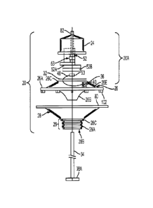
Blue FroRTM Circulator
[0016] FIG. I, an exploded view of circulator 20. illustrates most of the
unit's components
and their interaction. Diverter 28, the lower portion of the unit, includes an
inverted frusto-
conical shell of substantially circular cross section and substantially
straight sides. It has a
protruding edge around its upper periphery, outflow 80, which serves to guide
water
discharged from circulator 20 into laminar flow along the water surface. The
lower,
narrowest portion of the diverter has a collar 28C, below which is located a
substantially
cylindrical standard connection fitting 29, including concentric ridges 29A.
Diverter intake
28B is located inside connection fitting 29. These components are discussed in
detail below.
Drive shaft 34 extends through diverter intake 28B and mounts at its lower end
an impeller
hub mount 38A to which is removably attached the impeller and a plurality of
blades (not
shown here). Drive shaft 34 is made of stainless steel or a similar strong,
corrosion-resistant
alloy, and is about 11/2 inches in diameter in a present embodiment.
Optionally, impeller 38A
can be a helical screw.
[0017] Mounted above the diverter 28 is the circulator upper assembly 20A,
with a float
chassis 26. first including an upper frusto-conical shell 26E connected to a
flat
circumferential rim 26A, and mounting plate 32 mechanically attached to top
surface 26C of
float chassis 26 for use in mounting internal components discussed below. The
float chassis
26 has a wider lower base portion formed by the base of the frusto-conical
shell 26E and flat
circumferential rim 26A. This wider base provides stability of the circulator
in the water as
CA 02909784 2015-10-16
WO 2014/176388 PCT/US2014/035221
well as accommodating the shape of the sectional diverter 26B attached to the
lower portion
of float chassis 26.
[0018] When the lower base portion and the upper lip are the same diameter.
the radially out-
flowing water is formed into a wall which gravity can pull down and not
radially. When the
lower base portion has a diameter greater than the upper lip, the water
profile is triangular. By
the time the flow reaches the end of the lower base portion. there is a
substantial horizontal
vector and flow is radial away from the circulator.
[0019] The sectional diverter 26B resembles an inverted frustum of a cone with
substantially
parabolically curved sides inside and out. The upper edge of sectional
diverter 26B connects
to the bottom of float chassis rim 26A A plurality of supports 102 are
integrally attached to
the bottom of rim 26A to separate it from the outflow lip 80 when the float
chassis 26 and
diverter 28 are joined with mechanical connectors, as described below.
[0020] When assembled, the circulator 20 includes a motor cover 24 to protect
the electric
motor and other components, this cover being removably attached mechanically
to the top of
float-chassis 26. A lifting rod 82 is attached to the unit to facilitate
moving the assembled
unit. Lubrication for the rotating parts is provided by a PetromaticTM grease
cup 40 held by
grease cup holder 36 fastened atop the outer rim 26A of float chassis 26, with
a grease line 48
directing grease to bearing 53. An electric motor 52 is mounted on motor
mounts 52B and
connects to gear reducer 52A to drive the impeller attached to the impeller
hub 38A at a
suitable speed via drive shaft 34.
[0021] FIG. la provides a detailed view of the assembled circulator 20,
including motor
cover 24, float chassis 26 and diverter 28. Cover 24 is removably mechanically
connected to
the upper surface 26C of float chassis 26. Supports 102 are preferably molded
as integral
parts of the underside of rim 26A of float chassis 26, but can optionally be
fabricated
6
CA 02909784 2015-10-16
WO 2014/176388 PCT/US2014/035221
separately and attached by any suitable mechanical means. Float chassis 26 and
diverter 28
are mechanically connected by bolts 56 or other suitable mechanical connectors
passing
through bolt holes from the underside of outflow lip 80 into the undersides of
supports 102.
Supports 102 are of a height appropriate to optimize the flow of water
discharged through the
outflow spaces 97 between the underside of rim 26A of float chassis 26 and
outflow lip 80 of
diverter 28, and are streamlined. In one embodiment, outflow lip 80 is about
six inches wide.
[0022] The diverter intake 28B, within which the impeller operates, takes up
water into a
progressively expanding annular passage defined by the conical interior of
diverter 28 and the
parabolically curved exterior of the sectional diverter 26B. The intake water
then emerges
through outflow spaces 97 onto outflow lip 80 to flow in omni-directional
laminar flow
fashion onto the surface of the water in which the unit floats. The buoyancy
of the circulator
is designed so that it floats at a level such that water surface is above
outflow lip 80, with
water covering at least a portion of outflow spaces 97, and water surface
lying at about the
level of the underside of chassis lip 26A or lower. This produces a laminar
flow of water
initially having a height of about the height of outflow spaces 97.
[0023] The width of outflow lip 80 can be varied in different models to
optimize the
production of laminar flow for various volumes and rates of discharge. For
example, a four-
inch outflow space and six-inch outflow lip are effective in producing laminar
flow for a
discharge of about 7 million gallons/day (MG/D) using about three horsepower
in "mix
mode" (i.e. impeller 38a runs counterclockwise). When the unit is operating in
aeration mode,
i.e. impeller 38A runs clockwise, the multiple plane surfaces of diverter 28
(28D) and the
sectional diverter 26B (31), forming polygonal cross sections, are helpful in
producing some
bubbles in the water, which contribute to better mixing and aeration. In
aeration mode the
flow is 2MG/D.
7
CA 02909784 2015-10-16
WO 2014/176388
PCT/US2014/035221
[0024] Connection fitting 29 below (livelier collar 28C at the bottom of
diverter 28 includes
concentric ridges 29A and diverter inner surface inside (not shown in FM. 1),
Water can be
taken up directly through diverter intake 28.13 or through an intake tube (not
shown). Fitting
29 is designed to mate with a fitting for an externally corrugated/internally
smooth intake
tube.
Waste Processin2 Granules
[0025] Bacteria bond to mineral salts, e.g. CaCO3, to form a biofilm anchored
to rocks. The
colonizing bacteria form a synergistic biofilm on the heavy mineral. The
mineral salts
selected for use as granules, which encourages biofilm formation. The inner
bacteria are
obligate anaerobes, e.g. Methanosaeta. The outer bacteria are facultative
bacteria that
hydrolyze bio-solids into bio-liquids. The inner bacteria convert bio-liquids
into gas and
consume acid, raising pH.
[0026] The granule has interstitial fluid pathways to bring food in and waste
out of the
granule. The outer surface is facultative and these bacteria hydrolyze
suspended solids that
precipitate onto the granule. The solids become simple soluble compounds and
wind their
way into the granule interior. Fermenting bacteria serially shorten simple
soluble compounds
into acetic acid (C-)). Methane generating bacteria convert the C3 acid into
CI (3moles of CH4
plus lmole of CO?) and consume 8 electrons and 8 protons (acid).
[0027] The methane escapes and fluidizes small granules. The produced CO3
dissolves in
water and is converted into CO3-. The methanogens consume acid, so the local
pH is >7.5.
The phase diagram for carbonate shows that CO3= is first produced at pH = 7.5.
The fluidized
granules are mixed vertically by the rising CH4. but can also move
horizontally to populate
the entire pond bottom.
8
CA 02909784 2015-10-16
WO 2014/176388 PCT/US2014/035221
[0028] Without wishing to be bound, it is believed that the biochemistry of
sludge digestion
goes through the following steps. Waste is converted into living and dead
bacteria by aerobic
bacteria, producing CO2. This step is very different for different substrates,
as specialized
bacteria are needed for specialized substrate (i.e. industrial waste). Dead
bacteria are
hydrolyzed to simple liquids by facultative bacteria. This is a ubiquitous
step, since all
bacteria have similar element ratios. Facultative and anaerobic bacteria
serially ferment
simple liquids into acetic acid (C7), which lowers the pH in the pond.
[0029] Obligate anaerobes convert C7 into Ct (methane and carbon dioxide).
Acid is
consumed, raising the pH in the pond. If the methanogens are part of a
biofilm, H7 production
is also minimized. In the presence of Sulfur Reducing Bacteria (SRB), H2 is
converted to
H7S. When H7 is not formed, SRB remain inactive, thus preventing production of
H7S.
[0030] Up-flow reactors are used with suspended beads, also known as granules,
to digest
sludge. These granules can be manmade or naturally occurring. Naturally
occurring granules
have obligate anaerobes in the interior to convert liquid biochemical oxygen
demand (BOD)
into gas. A superficial coating of facultative bacteria consumes trace oxygen
and converts
biosolids (sludge) into liquid BOD. The anaerobes are protected from toxic
oxygen by the
oxygen scavenging of the facultative surface bacteria.
[0031] An embodiment of the present invention mimics up-flow reactors in waste
treatment
lagoons. Granules are multi-valence cation mineral based, primarily CaCO3,
calcium
phosphate of many moieties and more complex minerals like struvite (magnesium
based
mineral). In the present invention, CaCO3 seeds are formed in a high shear
field in the
presence of Ca ++ and CO; and air at a pH >7.5.
[0032] Carbonate anion forms when the water pH is equal to or greater than
7.5. Once
formed, the granules propagate naturally. The methane generators produce 3
moles of CH4
9
CA 02909784 2015-10-16
WO 2014/176388
PCT/US2014/035221
and one mole of CO2. The CO-, dissolves and becomes local carbonate (at micro
pH > 7.5).
Calcium is ubiquitous in wastewater because humans use only a fraction of
ingested calcium.
The difference is excreted and available for granule propagation.
[00331 Calcium is also available in ancient sludge gels. The divalent cations
bond to two
carboxylic acids and form biopolymers. With the divalent structuring,
recalcitrant sludge is
hard to dewater. When the divalent cation is extracted, the structure
collapses and bacterial
attack is easy.
[0034] The rising methane fluidizes small granules. mixing them with substrate
and calcium,
mimicking an up-flow reactor.
[0035] In an embodiment of the present invention the combination of two
distinct biofilms,
one aerobic and one anaerobic meets modern discharge requirements,
particularly at low
temperatures. The strategy employed in the embodiment is to have an aerated
permeable
matrix with a dissolved oxygen (DO) level greater than Img/1, wherein water
flows
substantially parallel to a vertical permeable matrix in fluid communication
with a granular
anaerobic biofilm at the base of the water column.
[0036] Permeable matrices with significant cross flow velocity are susceptible
to fouling and
need periodic cleaning. The vertical aerobic biofilm develops a natural
ecosystem that
includes grazers, shavers and filter feeders (e.g. sludge worms, insect larvae
and nematodes)
that eat bacteria. The worm castings are dense and sink rapidly, transferring
substrate to the
anaerobic granules.
[0037] The facultative granule's exterior hydrolyzes the castings into liquids
while the
interior converts liquids sequentially into gas and consumes acid. In the
natural process, the
final conversion from acetic acid (C2) into methane (CI) consumes acid and
raises the pH.
CA 02909784 2015-10-16
WO 201-4/176388 PCTIUS2014/035221
Produced CO) becomes C01= and eventually CaCO3. The granules grow and
propagate.
However, the granules only form once the micro pH reaches 7.5.
[0038] In FIG. 2, the vertical line at zero days is the first day in which the
pH = 7.5. Prior to
this date, the chemical oxygen demand (COD) was random: after this date, COD
declined
linearly. Colonizing bacteria that form the gas-forming biofilm populate the
granules, once
formed. The acid-consuming granule then creates CO3= anions locally to allow
granules to
grow. The small granules are fluidized by produced gas and colonize the bottom
of the entire
pond. The large granules sit on recalcitrant sludge and slowly digest it.
[0039] Sludge 300 (shown in FIG. 3) is a mixture of alluvial sludge 302,
having total solids
of less than 2.5%, and recalcitrant gelled sludge 304 comprising 2.5% or more
total solids.
The granules are sufficiently dense to pass through the alluvial sludge and
sit on top of the
recalcitrant gel to form a bio-granule fluidized bed 306.
[0040] In am embodiment of the present invention, seeds are formed in the
aerated shear
field of a Blue Frog" circulator (shown in FIG. 1) in which the impeller 102
runs in one
direction only (unidirectional rotation), but fluid flow alternates from one
direction to another
(intentionally cavitates). Seeds (granule precursors) are discharged at the
base of the water
column as they exit the Blue Frog" CSTR. The seeds grow and propagate as
discussed
above. Eventually the granular fluidized bed is intermediate between alluvial
and gelled
sludge. The alluvial sludge and granules are well mixed by produced gas.
However, the
gelled sludge is not.
[0041] The CO3-, indirectly produced by the granule, reacts with the Ca
stabilizing the gel
to form CaCO3. The immediate gel collapses to become alluvial sludge (i.e. un-
stabilized
sludge). The process is iterative over time. The gel layer thins and the
granule bed increases.
11
CA 02909784 2015-10-16
WO 2014/176388 PCT/US2014/035221
[0042] Typical treatment pond sludge is composed of: 10.8% total solids, 30.2%
volatile
solids, 22.900mg/kg TKN, 6,680mg/kg Total Phosphorus. N/P of 3.4:1, pH of
6.59,
10,100mg/kg Calcium, 782mg/kg Magnesium, and no detectable amounts of
Potassium and
Sodium.
[0043] Typical VS of anaerobic digestate (residual digestible solids) is 50%
VS. The
inventive process are 30.2% VS. Typical VS of raw solids is 70%. This is a
huge and
unexpected change because the anaerobic digester is at elevated temperature
(<35 C) and the
inventive process is <25 C. Note also the high Ca and TP numbers, suggesting
mineral
formation. Also note that soluble cations have flowed out of the sludge (K+&
Na + are ND).
The total solids are 10.8%, much higher than would be expected (5-8% TS).
[0044] The graph of a waste treatment pond in Marshville, NC shown in FIG. 4
is a 7 year
chart that shows two distinct sludge reduction zones: alluvial sludge and
recalcitrant sludge.
[0045] The Marshallville, GA chart (shown in FIG. 5) is a two-year study of
the sludge in a
municipal pond. After two years of granule treatment, the residual sludge is
5" deep (mean).
[0046] The Lyon county chart (shown in FIG. 6) is a two-year study of a
municipal sludge
holding pond.
[0047] The charts of FIG. 4 ¨ 6 show an initial sharp sludge decline due to
digestion of
alluvial sludge, and then a slow decline of recalcitrant sludge.
[0048] It should be noted that the embodiments of the present invention
installed in the ponds
of FIG. 4¨ 6 do not include vertical attached growth surfaces in fluid
communication with
the granule bed. However, unexpectedly ammonia levels were greatly reduced to
very low
levels once vertical attached growth surfaces where introduced to ponds in
addition to
granule fluidized beds, as shown in FIG. 7 and 8.
12
CA 02909784 2015-10-16
WO 2014/176388
PCT/US2014/035221
[0049] It is well accepted that bacterial activity shows a first order
response by slowing when
temperatures drop. For example, ammonia is well known to have a strong
dependency with
temperature. The nitrification bacteria responsible for ammonia generation are
inactive at
temperatures below 5 C.
[0050] Surprisingly, the reduction in biochemical oxygen demand (BOD) is
independent of
ambient temperature when an aerobic vertical surface is combined with
horizontal anaerobic
granules. BOD is the amount of dissolved oxygen needed by aerobic biological
organisms in
a body of water to break down organic matter at a specific temperature over a
defined period
of time.
[0051] The vertical surfaces provide substrates for colonization by aerobic
bacteria in a
surface biofilm. Additionally, worms and other aerobic organisms eat dead and
dying
bacteria. Thus, the surface biofilm is continuously rejuvenated. Moreover,
heavy worm
castings, i.e. organic matter digested by the worms, rapidly sink to the
anaerobic granule
biofilm at the bottom of the water column. As a result, food is transferred to
the granules via
the worm castings.
[0052] The rate-limiting step is conversion of castings into soluble BOD
(hydrolysis). The
facultative surface bacteria on the periphery of the granule perform the
process of
hydrolyzing the castings. The facultative bacteria, protecting the interior
obligate anaerobes
consume any toxic trace oxygen. The inner-granule anaerobic fermenters and gas
formers
convert soluble BOD sequentially into methane and CO). The rising methane and
CO) gas
fluidizes small granules and brings substrate and immature granules into
intimate contact.
[0053] The produced CO) dissolves in water. Once the pH rises to at least 7.5
the CO2
becomes CO. It should be noted however, that micro pH (pH at discrete points
in the pond)
may be higher than macro pH because the granules consume acid.
13
CA 02909784 2015-10-16
WO 2014/176388 PCT/US2014/035221
[0054] The carbonate extracts Ca from the sludge gel, destabilizing it. The
resultant CaCO3
is used to increase the size of the granules and form new granules. The
bacteria bind the
CaCO3 to the granule with a bacteria-produced glue to increase the size of the
granule.
[0055] Once destabilized, the previously-recalcitrant gel becomes alluvial
biosolids. Bacteria
use the local CaCO3 to form a biopolymer that glues the granule together. The
methane gas
rises through the water column to the surface, which fluidizes the gel-free
immature granules.
[0056] The alluvial sludge is digested in situ. The granules are dense enough
to sink through
the alluvial sludge, but they do not penetrate the gel-structured recalcitrant
sludge. After
about one year, the alluvial sludge is digested leaving entering solids and
recalcitrant sludge
to be digested. The new sludge (i.e. incoming solids, aerobic produced
biosolids and fresh
worm castings) is alluvial because new biosolids rain down from above without
yet forming a
new gel. The granules have capacity to handle this load.
[0057] Recalcitrant sludge is difficult to digest because the granules are in
intimate contact
only on the substantially spherical granule's contact surface area with
substantially flat
recalcitrant sludge's gelled structure. Only the granule's lower surface, in
direct contact with
recalcitrant sludge, has the opportunity to digest. Thus, recalcitrant sludge
is digested slowly.
[0058] At a final equilibrium, there are "only" granules on the pond floor.
This process can
be viewed indirectly by reviewing long term BOD data. Long-term BOD results
can be
divided into two zones: alluvial digestion and recalcitrant digestion.
[0059] The vertical black line in FIG. 10 indicates installation of the Blue
Frog System
(BFS), a series of circulators with attached growth vertical spokes and a
horizontal granule
bottom. During the first 12 months, the BOD jumped up and down in a declining
harmonic
decay. As granules produced gas, some of the gas occludes to large solids and
lifts them up to
14
CA 02909784 2015-10-16
WO 2014/176388
PCT/US2014/035221
the surface in so-called sludge eruptions. The gas escapes, the structured gel
breaks up, and
rains back down, unstructured.
[0060] Some of the solids become soluble and/or suspended solids. The BOD &
total
suspended solids (TSS) peak. Soluble BOD is converted to solids and sinks
causing the BOD
to fall. Once the solids available to produce lifting-gas are digested, the
system enters the
recalcitrant sludge digestion phase. BOD varies, but the trendline is down
into single digits.
[0061] The recalcitrant sludge depth is about 6 inches. The fluidized bed is
12 ¨ 18 inches
above the recalcitrant sludge blanket. This phenomenon is observed in other
locations where
granules are formed with vertical spokes.
[0062] Unexpectedly. an in-situ sludge-digesting process in which the
combination of a
vertical, self-cleaning immobile surface with a horizontal, mobile self-
cleaning surface
creates an environment where BOD reduction is independent of ambient
temperature. The pH
has to be greater than 6.2 and preferably at least 7.5. The vertical surface
dissolved oxygen is
greater than Omg/l.
Yellow Frog Aerator
[0063] The yellow frog (YF) 1302 shown in FIG. I3A ¨ 13C is an apparatus for
making
vertical-rising bubbles move horizontal. Bubble escape velocity is
proportional to bubble
radius until the bubble is greater than about lmm. Thereafter the escape
velocity is constant.
The internal components of the YE 1302 are similar to those shown in FIG. 1,
thus only
distinguishing features will be described hereinbelow.
[0064] Aerators are historically designed to maximize droplet macro surface
area (number of
drops x area/droplet) in air, or make air bubbles small (greater macro surface
area) and deep
(more detention time for oxygen transfer). These strategies consume large
amounts of energy
by throwing water up into the air or pushing Ras deep into the water column.
Many
CA 02909784 2015-10-16
WO 201-1/176388
PCT/US2014/035221
inventions have been made to increase the oxygen transfer rate (OTR). OTR is a
helpful way
to measure efficiency in aerobic systems (lbs 02/hp x hr).
[0065] OTR is an inelegant measure in hybrid systems wherein air is added, but
much of the
remediation takes place in anaerobic granules. OTR explicitly assumes that
100% of
remediation is aerobic. For example if half the BOD were removed aerobically
and half
anaerobically, the reported OTR of the aerators would double.
[0066] It is well known that when bubbles rise to the surface, the elevation
of the gas/liquid
mixture rises and fluid flows radially away from the bubble. If bubbles are
added in a line.
e.g. from an aerator hose, the flow is left and right from the axis of the
hose.
[0067] If droplets are thrown radially from a splasher aerator, the drops have
a horizontal and
vertical vector. The horizontal vector makes the fluid flow away from the
splasher.
[0068] The YF 1302 is an improved aerator that decouples bubble formation and
fluid flow.
YF 1302 is a circulator with radial surface outflow 1304, a water intake 1306,
air intake
1314, and two sets of four concentric rings of aeration hose 1308 connected to
the air intake
1314.
[0069] The concentric rings 1308 are positioned at sufficient position apart
below the surface
of the water for the emission of microbubbles to rise between the aeration
hoses of the upper
set of concentric rings. In an embodiment, the concentric rings are positioned
at about 9
inches and about 18" below the surface, respectively. In this configuration,
the prior art
would suggest that there is insufficient detention time for oxygen transfer
(i.e. before the
bubbles flowed up and out of the water column). Additionally, the lower
(second) set of
concentric rings 1308 are staggered with respect to the upper (first) set of
concentric rings
1308, such that micro-bubbles emitted by the lower set of concentric rings
1308 rise between
the aeration hoses of the upper set of concentric rings 1308. The above
positioning of the
16
CA 02909784 2015-10-16
WO 2014/176388
PCT/US2014/035221
concentric rings 1308 is intended for illustrative purposes. The upper
concentric ring is
positioned more than 2 times deeper in the water column than the depth of the
water
discharge from the radial surface outflow 1304 with respect to the surface of
the water. At
twice the depth, the air bubbles emitted by the upper set of concentric rings
1308 are below
the wave/no wave interface created by the water discharge.
[0070] In an embodiment, each of the two sets of concentric rings 1308 is
connected to a
respective air intake 1314, such that the flow between the upper set of
concentric rings 1308
and the lower set of concentric rings 1308 is equalized. Since there is a 9
inch gap between
the upper set of concentric rings 1308 and the lower set of concentric rings
1308, higher air
pressure is needed to push air to the lower set of concentric rings 1308.
[0071] The bubbles are externally produced at an intermediate elevation
between the aerator
inlet and outlet. If the bubbles are produced below the inlet, the bubbles get
sucked into the
inlet and coalesce. If the bubbles are produced above the outflow, the bubbles
escape and do
not flow horizontally.
[0072] As shown in FIG. 13A, the water exiting from radial surface outflow
1304 is
introduced below the water surface 1310. Additionally, the introduction of
micro air bubbles
into the water column creates a region of low viscosity 1314 in comparison to
the
surrounding water. Thus a boundary 1316 is created between the typical, high
viscosity water
1312 and lower viscosity aerated water 1314. This boundary 1316 acts to dampen
the rate of
rise of the micro air bubbles. As a consequence the micro air bubbles are
directed
horizontally for an extended distance before reaching the water surface 1310.
[0073] Radially outflowing. well-mixed, water hydraulically redirects rising
bubbles
horizontal, i.e. redirection is not with machines or steering means. Bubbles
less than lmm
radius are re-entrained in the diverging surface flow lines. The diverging
flow lines separate
17
CA 02909784 2015-10-16
WO 2014/176388 PCT/US2014/035221
individual bubbles one from another to prevent coalescing and consequent loss
of macro
surface area.
[00741 The radial, well-mixed, substantially gas-free. outflow is non linear
and eddies are
formed that continuously re-entrain bubbles of less than lmm radius. When
small bubbles are
re-entrained, detention time is increased sufficiently for oxygen to transfer
to the water.
[0075] In an embodiment of the YF aerator 1302, only one set of concentric
rings 1308 is
provided. In another embodiment more than two sets of concentric rings 1308
are provided,
each disposed at different vertical positions.
[0076] Additionally, an embodiment of the YF aerator 1302, as shown in FIG.
13B and 13C,
is in fluid communication with radial, vertical, semi-permeable, attached
growth surfaces
1404 disposed from radially extending spokes 1402. For clarity of the
structure, FIG. 13B
only shows two spokes 1402 and growth surfaces 1404 attached to the floating
spoke and
hanging vertically down, with a weighted pipe at the lower edge of the growth
surfaces 1404
that keeps the growth surface substantially vertical. However, in actuality
the YF 1302 of the
present invention has a plurality of spokes 1402, as shown in FIG. 13C,
extending radially
from the central axis of the YF 1302 and spaced at intervals about the
circumference of the
YB 1302. With the growth surfaces 1404 disposed as shown in FIG. I3B, large
radius
bubbles, greater than lmm radius, obstructed from reaching the water surface
for a period of
time sufficient to discharge their oxygen to the attached growth surface. The
attached growth
has a DO greater than lmg/1 for a spoke length of 15 feet. The spokes 1402 and
growth
surfaces 1404 are optionally equipped on the YF 1302 when a specific waste
treatment
project would benefit from the additional vertical growth surfaces as
discussed above, for
example if carbon and or nitrogen reduction is desired. Thus, the YF 1302 of
the present
invention encompasses both embodiments with and without the spokes 11402 and
growth
surfaces 1404.
18
CA 02909784 2015-10-16
WO 2014/176388 PCT/US2014/035221
[0077] As shown in FIG. 13C the spokes 1402 are not mechanically connected to
the YF
1302, but rather float freely and substantially encircle the YF 1302. In the
embodiment shown
in FIG. 13C a large opening is provided at one side of the arrangement of
spokes 1402 to
allow easy access to and removal of the YF 1302. However, the spokes 1402 may,
in an
embodiment, form a completed circle around the YF 1302. Each of the spokes
1402 are
connected to adjacent spokes 1402 by connecting members 1406 and 1408. Long
connecting
members 1406 are disposed on the outside perimeter of the arrangement, while
shorter
connecting members 1408 are disposed on the inside perimeter. This arrangement
of
connecting members 146 and 1408 forces the spokes into a radial configuration.
The length
of the long connecting members 1406 and short connecting members 1408 are
determined by
the length of the spokes 1402 and the desired angle formed between adjacent
spokes 1402.
[0078] It was determined experimentally that aerobic conditions do not exist
beyond spoke
lengths of 15 feet. The anaerobic section grows a 10" thick slime that sinks
the tip of the
spoke. The spokes are intentionally shortened to insure that the entire growth
surface is
sufficiently aerated that the shavers and grazers have sufficient oxygen to
thrive. For
example, spokes may be 10ft long, with a growth surface of 27" deep and 2"
thick.
[0079] The aerobic matrix, i.e. the growth surface 1412, is self-cleaning as
long as it is
aerobic. The natural color of the matrix is black. The in-use color is tan.
[0080] The matrix total volume is populated with sludge worms, insect larvae
and nematodes
(round worms). The worms graze on the colonizing bacteria and eat the
bacteria. The grazers
keep the matrix clean (self-cleaning), if the DO is greater than lmg/l. This
has a surprising
result in that nitrifying bacteria can compete with carbon-consuming bacteria
in a carbon¨
rich, aerobic environment. This has an enormous benefit in cold weather
ammonia reduction.
19
CA 02909784 2015-10-16
WO 2014/176388
PCT/US2014/035221
[0081] The prior art teaches that nitrifiers cannot compete successfully with
carbon bacteria,
so processes must be designed with nitrification late in the process after all
the incoming
warmth has been lost. Cold weather ammonia reduction is unsuccessful when the
attached
growth surface is fouled with ice. However, warm water operation, where water
temperatures
are above 5 C, is very effective at ammonia reduction.
[0082] The unexpected result was to put the attached growth spokes in Cell
where warmth
is more important than competition with carbon bacteria. Nitrification
bacteria do not
perform at temperatures of less than 5 C, and carbon bacteria outcompete
nitrification
bacteria when the carbon bacterial population is huge (e.g. in an aeration
basin with RAS
-5,000mel TSS).
[0083] On a self-cleaning surface, the worms reduce the absolute bacteria
count. In a
traditional system, the carbon bacteria (heterotrophs) can grow 100x faster
than the
nitrification bacteria (autotrophs) such that they grow right over all the
nitrifiers. This has the
effect of increasing the oxygen diffusion resistance. By creating a self-
cleaning environment,
oxygen diffusion to the growth surface is increased, allowing nitrification
bacteria to compete
in a carbon-rich environment. Thus, there is surplus oxygen available for the
slow growing
nitrifiers. Consequently, competition between the nitrifiers and carbon
bacteria for necessary
oxygen is minimized. The various bacteria do not have to compete for scarce
oxygen because
oxygen is no longer scarce.
[0084] Instead of adding expensive oxygen to match the bacterial population,
the self-
cleaning spokes in fluid communication with diverging well-mixed aerobic water
reduce the
bacterial population instead.
[0085] The YF circulator pumps 7MG/D of water through an annular space 4
inches high
with a diameter of 7ft (7.33ft2). The exit velocity is less than 2ft/sec.
Turbulent flow in clean
CA 02909784 2015-10-16
WO 2014/176388 PCT/US2014/035221
water is typically established at velocities greater than or equal to
approximately 7ft/sec.
Substantially non-turbulent flow leaves the YF flowing radially and
horizontally away from
the centerline of the YF. However, the impeller, turning a slow 144rpm,
imparts a slight
counterclockwise curvilinear flow pattern with a distinct cross vector that
moves water right-
to-left as well as out from the centerline.
[0086] As water flows out from the YF 1402, coarse and fine bubbles rise
vertically into the
horizontal gas-free, non-turbulent water flow. The coarse and fine bubbles are
entrained in
the outflowing eddies to a diameter of 50ft. Non-turbulent flow minimizes
bubble coalescing.
The bubbles remain in the water column much longer so there is sufficient
detention time to
transfer bubble-interior oxygen to the water. This results in a 5-fold
increase in oxygen
transfer efficiency to 31bs 02/ hp x hr.
[0087] The YF 1402 of the present invention provides the following
improvements over prior
art designs:
Non-turbulent outflow from the circulator to create eddies that continuously
re-entrain
small bubbles without coalescing them into large bubbles;
Sufficient hose length to produce micro-bubbles (e.g. 2 linear feet of 1"
diameter hose
per cubic foot of air),
a. Inside the chassis of prior art designs there is insufficient room to fit
the
required length of hose (e.g. in the previous YF design, the maximum amount
of linear feet of hose was 1 linear foot per cubic foot of air added);
Curvilinear outflow with a significant visible cross-flow vector salvages
large bubbles
occluding them to the growth surface for a time sufficient to transfer their
interior oxygen
to the growth surface;
One header: one set of concentric rings to offset the 9" pressure difference
between
the upper and lower set of hoses,
21
CA 02909784 2015-10-16
WO 2014/176388
PCT/US2014/035221
b. This makes sure that airflow is substantially equalized between the lower
set
of rings and the upper set of rings,
i. Skilled artisans may place all the rings on the same level without
deviating from the present invention;
External bubble generation with an elevation intermediate between the
circulator
(pump) inlet and outlet,
c. If the bubbles were below the inlet, some of the bubbles would be sucked
into
the inlet and coalesce,
d. If the bubble were above the outlet, they would not be entrained in the
horizontal outflowing water; and
External hoses,
e. This prevents trash fouling of internal hoses and inhibits bubble
coalescing
inside the pump chassis,
i. Trash flows through the pump and then over the submerged rings
without contacting the rings.
[0088] In another embodiment, multiple YF 1402 are an-anged in clusters. When
two aerators
are closer than 80ft (center-to-center), the outflow from one aerator and an
adjacent aerator
have equal and opposite horizontal vectors. When these vectors meet, a
hydraulic wall is
formed. When two splashers throw droplets into the air, a hydraulic wall forms
where the
droplet horizontal vectors are equal and opposite. But hydraulic walls are
transfer vectors for
moving surface substrate down to the horizontal granules on the pond floor.
Some clusters
have hydraulic walls wherein the number of hydraulic walls is the same or
greater than the
number of circulators.
[0089] Hydraulic walls are particularly valuable when maximizing growth of
nitrifiers in
cold weather. The walls transport ammonia and produced nitrite down to the bio-
granules.
22
CA 02909784 2015-10-16
WO 2014/176388 PCT/US2014/035221
Over time a very specialized, well-known bacterium (Anammox) converts ammonium
and
nitrite directly into nitrogen gas. Very low winter ammonia levels become
possible.
[0090] What is unexpected is that that when vertical bubbles rise into well-
mixed radially
outflowing surface water that aerator efficiency doubles to 21bs 01/hpxhr.
[0091] When such an aerator is combined with radially aligned, semi-permeable
matrix
surfaces, such as in the YF 1402 described above, the aerobic surface becomes
self-cleaning
and nitrification bacteria can compete successfully with carbon bacteria in an
oxygen stressed
environment.
[0092] In addition, when aerators and spokes are clustered such that the
number of hydraulic
walls is equal to or greater than the number of circulators, then cold weather
nitrification is
possible in the warmest cell in the system.
Gold Frog
[0093] The Gold Frog (GF) 1502, shown in FIG. 14, is an aerator with one or
more air jets
1518 for injecting an external source of air bubbles at a vertical position
between the water
inlet 1506 and water outlet 1504. The injected air bubbles rise under the well-
mixed radially
outflowing water ejected from the water outlet 1504. The rising air bubbles
elevate the
outflowing water above the mean elevation of the surrounding water such that
gassy water
flows left and right. The internal components of the GF are similar to those
shown in FIG. 1,
thus only distinguishing features are shown in FIG. 14.
[0094] In an embodiment of the present invention, two impinging venturis 1512,
are disposed
within the air jets 1518 in order to generate a high volume of micro air
bubbles in a jet of
water emitted through the air jet 1518. Water is drawn into the venturis 1512
through a water
inlet 1508 and piping 1510. Additionally, air intake hoses 1514 are provided
above the water
surface which feed air to the venturis 1512 by way of respective air hoses
1516. Each of the
23
CA 02909784 2015-10-16
WO 2014/176388
PCT/US2014/035221
impinging venturis 1512 directs jets of micro air bubbles at one another at a
closing velocity
of approximately 7ft/sec and a downward angle of 15 . Flow rates between 2MG/D
and
7MG/D will work. Skilled artisans can adjust the downward angle to maximize
detention
time in the water column without deviating from the present invention. The
impingement
fractures small bubbles into micron-sized bubbles; the downward angle
maximizes the time
the bubbles are in the water column.
[00951 The shear from impinging venturis 1512, wherein each venturi 1512 has
turbulent
flow, will hydrolyze triglycerides into fatty acid and glycerin. The fatty
acid (soap) in turn
lowers the surface tension of the water. Lower surface tension ("wetter water-
) is particularly
advantageous with land application of wastewater from manure ponds and
municipal waste.
[0096] Wetter water soaks into soil faster and does not form puddles or run
off into streams.
In a municipal waste lagoon system with a OF 1502, surface tension was reduced
17.5%. In a
dairy-processing lagoon, the surface tension was reduced 49.9% (to 36.35mN/m).
In a dairy
manure lagoon, surface tension was reduced 39.6%.
[00971 What has also been discovered is that the impinging venturis physically
rupture
bacteria, like E.coli, and also rupture large algae. Micro algae about lmicron
diameter are not
ruptured. In a municipal holding pond, the algae actual count were reduced 50%
when
passing through the OF.
[00981 The 17.5% reduction in surface tension in the municipal pond is due to
physically
rupturing the bacteria and algae and then hydrolyzing the minute stores of fat
in individual
organism. The 49.9% reduction in surface tension in the dairy processing pond
is a
combination of direct hydrolysis of dairy processing fat plus the rupturing
and subsequent
hydrolysis of bacterial fat. The dairy pond did not have algae. Hydrolyzing
the fat that
entered the dairy manure lagoon lowered the surface tension.
24
CA 02909784 2015-10-16
WO 2014/176388
PCT/US2014/035221
[0099] Originally, the design of the GF venturis had significant backpressure
(sum of friction
flow in the transfer piping, 2ft submersion from the surface and backpressure
from 7MG/D
flow through the annular space at the GF outlet.)
[0100] The present embodiment eliminates hoses inside the chassis that
transfer gassy water
present in the prior art. The impingement T is rotated horizontal to an
elevation intermediate
between the inlet and the outlet of the circulator. The impingement T exit is
angled at -150
from the horizontal such that each pair of venturis discharges microbubbles
down-then-up
such that the net flow is horizontal and under the outflowing laminar gas-free
water.
[0101] Microbubbles generated by the GF 1502 rise up into the outflowing
laminar flow and
are entrained and made to move horizontally without any one stream
intersecting with the
adjacent stream, doubling the efficiency over the prior art.
[0102] Thus like the YF embodiment, the GF embodiment discharges gas at an
intermediate
elevation between the pump inlet and outlet where externally-generated bubbles
rise
vertically into horizontal outflowing laminar flow with a flow vector aligned
with the
centerline of the circulator and a flow vector at right angles to the
centerline flow vector.
[0103] An embodiment of the GF 1502 removes the transfer line and the flow
resistance and
redirects the impingement T so that the discharge from the air jet 1518 is
about -15 below
the horizontal, about 4 inches below the water surface. The combination of
eliminating back
pressure and directing free flowing gassy fluid at an angle below the
horizontal increased
oxygen transfer efficiency by 400%.
[0104] Operating at low backpressure is well known. What is unexpected is
combining low
backpressure venturi operation with horizontal radial outflowing gas-free
water after
impingement mixing below horizontally outflowing gas-free water to detain
bubbles in the
water column for a time sufficient to extract 20% of the oxygen.
CA 02909784 2015-10-16
WO 2014/176388 PCT/US201-1/035221
[0105] The venturi-equipped GF 1502 pulls 2,023Ibs 02/day through the sum of
the venturis.
The measured oxygen transfer rate (OTR) is ¨4x (max OTR = 6.51bs 02/hp x hr)
the high
backpressure prior design of 0.241bs 02/hp x hr.
[0106] In the world of mechanical aerators, this is a low efficiency aerator.
However, the GF
1502 provides additional advantages. The GF 1502 adds oxygen, lowers surface
tension,
lowers E.coli, and lowers TSS. In combination with a circumferential baffle
and a YF, very
low suspended solids are achievable.
[0107] The combination of a freestanding, wave-generating circulator with a
low
backpressure venturi impingement mixer (i.e. GF 1502) with a circumferential
baffle creates
continuous waves that partially clarify the wavy section of the pond. Gravity
pulls particles
down. Friction force also pulls particles down during the rising,-wave half of
the wave cycle.
The produced "sweet" layer (-6") is low in TSS. Therefore, lower density and
lower viscosity
is achieved. Thin, light surface water races to the outside of the baffle and
eventually enters
the baffled zone at the base of the water column.
[0108] Impingement mixer aerator (GF 1502) centrifugally separates solids, and
bacteria
(including pathogens) and algae are physically ruptured and their stored fat
is hydrolyzed into
fatty acid. Effluent is removed from the quiescent settling section as well.
[0109] The described embodiments of the present invention are intended to be
illustrative
rather than restrictive, and are not intended to represent every embodiment of
the present
invention. Various modifications and variations can be made without departing
from the
spirit or scope of the invention as set forth in the following claims both
literally and in
equivalents recognized in law.
26