Note: Descriptions are shown in the official language in which they were submitted.
CA 02909809 2015-10-19
WO 2014/172686
PCT/US2014/034726
SYSTEMS AND METHODS OF MOORING AN ARRAY OF WAVE ENERGY
CONVERTERS
[0001] This application claims priority to U.S. provisional application having
serial number
61/814108, which was filed 19-Apr-13.
Field of The Invention
[0002] The field of the invention is ocean mooring systems and methods
therefor, especially
as they relate to mooring systems for floating wave energy converters that
convert the energy
of wave motion into mechanical and/or electrical energy.
Background of the Invention
[0003] The background description includes information that may be useful in
understanding
the present invention. It is not an admission that any of the information
provided herein is
prior art or relevant to the presently claimed invention, or that any
publication specifically or
implicitly referenced is prior art.
[0004] Energy extraction form moving bodies of water is well known, and
typical examples
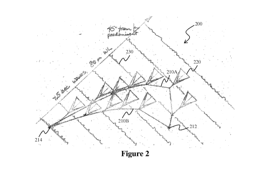
for energy converters are implemented as submerged turbine systems that
generate electrical
energy from ocean or freshwater currents using a propeller-type structure as
described, for
example, in GB2497961 or US 8664790. Alternatively, a louvered turbine can be
used to
produce electric energy as discussed in US 8664784. As will be readily
appreciated, such
energy converters will require an anchor or tether structure to prevent loss
or damage to the
converter. Depending on the type of converter, anchoring can be done using
known subsea
foundations or suction piles. On the other hand, where the energy converter is
installed in
relatively shallow bodies of water (e.g., less than 100 m depth), where the
vertical position
relative to the sea bed must be adjustable, or where tidal flow reverses the
flow direction of
the water relative to the turbine, installation of the submerged energy
converters may also be
implemented via a tether structure as shown for example, in GB 2256011, WO
88/04362,
WO 2012/123704, US 2010/0230971, US 6531788, or US 2010/0326343.
[0005] All publications identified herein are incorporated by reference to the
same extent as
if each individual publication or patent application were specifically and
individually
indicated to be incorporated by reference. Where a definition or use of a term
in an
incorporated reference is inconsistent or contrary to the definition of that
term provided
1
CA 02909809 2015-10-19
WO 2014/172686
PCT/US2014/034726
herein, the definition of that term provided herein applies and the definition
of that term in
the reference does not apply.
[0006] Other examples for energy converters are implemented as floating energy
converters
that extract energy from the motion of water in a wave passing the energy
converter. The
term "wave energy converter" as used herein refers to a device that floats on
the surface of a
body of water while extracting energy (via lift, rotation, and/or tilt
relative to the sea bed)
from the circular motion of water particles passing the wave energy converter.
Thus,
submerged turbine devices based on the bulk flow of water are expressly
excluded from the
meaning of the term 'wave energy converter'. To maximize energy harvest, wave
energy
converters can be deployed in relatively large arrays to aggregate their power
production,
which requires that each wave energy converter occupies an area under the
influence of
changes in wave, current, and wind direction within which no other WEC is
permitted. Thus,
it is readily apparent that arrays of wave energy harvesters will occupy
substantial areas. As
each single wave energy converter requires in most cases between one and four
mooring
structures (see e.g., US 2014/0090365, EP 2713042, US 8686582, or WO
2013/182837),
currently known moorings in arrays are environmentally disruptive to the sea
bed and present
a substantial financial burden. Compounding such difficulties is the fact that
each mooring
anchor must be able to withstand the maximal forces to which a single wave
energy converter
can be subject under extreme conditions. Not surprisingly, the cost of such a
complex set of
moorings and connections rival the costs of the wave energy converters
themselves.
[0007] Moreover, each WEC has a power line, whether electrical or fluid-
transporting, which
is typically hooked into a manifold on the sea bed. As a result of current
design, wave energy
converter farms must often cover a large area, require extensive cable
lengths, and often need
a significant number of mooring anchors. In addition, sea life and especially
whales tend to
become entangled or injured by the multitude of mooring lines in arrays of
wave energy
converters, which further raises ecological concerns. While tether structures
are conceptually
relatively simple and allow for flexibility for at least some of the submerged
turbine systems
as described above, tether structures are often deemed not suitable or even
applicable to
floating energy converters. For example, individual tether structures are
thought to be easily
tangled if not sufficiently spaced apart or prone to breaking due to tensional
forces where
multiple wave energy converters are attached to a single tether.
2
CA 02909809 2015-10-19
WO 2014/172686
PCT/US2014/034726
[0008] Therefore, while many mooring structures for marine energy converters
are known in
the art, all or almost all of them suffer from one or more disadvantages,
particularly where
multiple wave energy converters are to be deployed in an array. Consequently,
there is still a
need for improved systems and methods of mooring an array of wave energy
converters.
Summary of the Invention
[0009] The present inventive subject matter is drawn to various systems,
configurations, and
methods of mooring wave energy converters in an array in which a plurality of
wave energy
converters are coupled to a primary tether via respective secondary tethers.
Most preferably,
the primary tether is coupled to the seabed via one or more anchors, and
larger arrays can be
manufactured from multiple primary tethers (which may or may not be coupled on
one end to
the same anchor at the seabed) each carrying multiple secondary tethers while
the spacing of
the secondary tethers is preferably such that at least two of the wave energy
converters are
not positioned at the same time at the wave maximum of a passing wave. Viewed
from
another perspective, the length of the secondary tethers (and in some cases
also the length of
the primary and secondary tethers) are chosen such that at least two, more
typically at least
half, and most typically all of the wave energy converters have a distance
between successive
converters as measured along an axis parallel to the motion of a passing wave
that is shorter
that the shortest wavelength that is typically encountered at the location of
the array (while
the wave travels in the predominant direction). It should be particularly
noted that such
arrangement advantageously reduces tension forces on the primary tether and
anchor to
which the primary tether is coupled, reduces the ratio of mooring lines per
energy converter
in an array and thus the potentially adverse impact on the environment, as
well as reduces
complexity and deployment of a wave energy converter array. Most typically,
the spacing of
the secondary tethers is chosen such that each floating wave energy converter
has all degrees
of freedom on the surface of the water without at least two (and most
typically all) of the
converters contacting each other or overlapping their respective secondary
tethers.
[0010] Thus, especially preferred systems and methods afford for flexible
mooring of a large
number of wave energy converters using a significantly reduced number of
mooring lines.
Moreover, systems and methods contemplated herein also allow for simple and
effective
production of large arrays of wave energy converters that can be easily
deployed and
maintained in a cost effective as well as environmentally friendly manner.
3
CA 02909809 2015-10-19
WO 2014/172686
PCT/US2014/034726
[0011] In one aspect of the inventive subject matter, a mooring system for an
array of wave
energy converters comprises first and second sea bed anchors that are coupled
to a primary
tether. A plurality of secondary tethers, each having first and second ends,
are coupled to the
primary tether via respective first ends, and each of the second ends has a
coupling
mechanism that allows the secondary tether to retain a wave energy converter.
The secondary
tethers are coupled to the primary tether at predetermined distances along a
length of the
primary tether.
[0012] In some aspects of the inventive subject matter, the length of the
primary and/or
secondary tethers is chosen such that at least two of the wave energy
converters have a
distance of separation (as measured along the axis that is parallel to the
motion of a passing
wave) that is shorter than the shortest wavelength typically encountered at
the location of the
array (e.g., less than 50m, less than 40m, less than 30m, less than 20m, less
than 10m).
Additionally, it is contemplated that the length of the primary and/or the
secondary tethers is
chosen such that the primary and/or secondary tethers are suspended off the
seabed. While
not limiting to the inventive subject matter, it is also contemplated that the
primary tether has
a fixed length while the secondary tether may be adjustable in length.
Additionally, it is
contemplated that the primary tether and the secondary tether have at least a
ten to one length
ratio.
[0013] Where desired, it is contemplated that the mooring system may further
include a
tertiary and optionally a quaternary tether coupled to the primary tether,
wherein the tertiary
and optionally quaternary tethers have a length that restricts side-to-side
motion of the
primary tether, and are preferably coupled to third and fourth seabed anchors
located behind
the first and second anchors for the primary tether (as seen in direction of
the wave trave). In
further aspects, at least a second primary tether may be coupled via at least
one end to the
first and/or second sea bed anchors, and the second primary tether may further
comprise a
second plurality of second secondary tethers. It should be noted that the
length of the tertiary
and/or quaternary tethers may be adjusted in response to a measured wave
direction, wave
amplitude, and/or current direction.
[0014] Therefore, and viewed from a different perspective, a mooring system
for an array of
wave energy converters is contemplated that includes a plurality of primary
tethers to which a
plurality of secondary tethers are coupled, respectively, wherein the
secondary tethers are
coupled to the respective primary tethers at predetermined distances along a
length of the
4
CA 02909809 2015-10-19
WO 2014/172686
PCT/US2014/034726
primary tether, and wherein at least two of the primary tethers are coupled to
a shared seabed
anchor.
[0015] In such mooring systems it is contemplated that the length of the
primary and/or
plurality of secondary tethers is chosen such that at least two the wave
energy converters
when coupled to the secondary tethers have a distance of separation (as
measured along an
axis parallel to the motion of a passing wave) that is shorter than the
shortest wavelength that
is typically encountered at the location of the array. Additionally, primary
tethers may be
coupled to respective tertiary tethers in contemplated mooring systems, and/or
contemplated
systems may further include at least three primary tethers that are coupled to
the shared
anchor. Most typically, the primary tethers and the secondary tethers have at
least a five to
one, or at least a ten to one length ratio.
[0016] In other aspects of the inventive subject matter, an array of wave
energy converters is
contemplated that includes a plurality of wave energy converters that are
coupled to a
common primary tether via respective plurality of secondary tethers, wherein
the primary
tether has a first end and a second end, and wherein the first and second ends
of the primary
tether are coupled to first and second seabed anchors, respectively.
[0017] As indicated before, it is contemplated that at least two, or at least
three, or at least
four wave energy converters may be coupled to a primary tether, and that a
second primary
tether may be coupled to the first and/or second seabed anchors.
[0018] Consequently, the inventors also contemplate a method of wave energy
converter
deployment that includes a step of coupling a first and a second wave energy
converter to a
primary tether through respective first and second secondary tethers. In
another step, one end
of the secondary tethers is coupled to the wave energy converter and another
end of the
secondary tether is coupled to the primary tether, wherein the secondary
tethers are coupled
to the primary tether at predetermined distances along a length of the primary
tether.
[0019] Contemplated methods will also include a step of first coupling an
anchor to the
primary tether, and then coupling the secondary tether to the primary tether,
and/or a step of
first deploying an anchor, the primary tether, and the secondary tether
coupled to the primary
tether, and then coupling the wave energy converters to the secondary tethers.
Alternatively,
contemplated methods may comprise a step of supplying the secondary tether
with a buoyant
element.
CA 02909809 2015-10-19
WO 2014/172686
PCT/US2014/034726
[0020] In still further aspects of the inventive subject matter, a method of
adjusting length of
a secondary tether length is contemplated where the secondary tether secures a
wave energy
converter. In such methods, a location characteristic of a wave energy
converter is detected,
and then a calculated location is determined for a desired power generation
factor. In another
step, length of the secondary tether is increased or decreased to thereby
achieve the desired
power generation factor.
[0021] While not limiting to the inventive subject matter, a global
positioning system may be
used to determine the location characteristic of the wave energy converter,
and/or the location
characteristic may be determined relative to at least one other wave energy
converter.
[0022] In yet another aspect of the inventive subject matter, a method of
transferring power
harvested by a wave energy converter to a main power line is contemplated that
includes the
steps of transforming ocean wave energy into potential or electrical energy
through the use of
the wave energy converter, and another step of transferring the potential or
electrical energy
from a generator line of the wave energy converter to a main power line
through fluid,
conductive, or inductive coupling, wherein the generator line is configured as
or coupled to a
secondary tether and wherein the main power line is configured as or coupled
to a primary
tether. Additional potential or electrical energy may be transferred from a
second generator
line of a second wave energy converter to the main power line.
[0023] Various objects, features, aspects and advantages of the present
invention will become
more apparent from the following detailed description of preferred embodiments
of the
invention along with the accompanying drawing.
Brief Description of the Drawing
[0024] Figure 1 is an exemplary schematic illustrating a mooring system
according to the
inventive subject matter having two primary tethers and 11 wave energy
converters coupled
to the primary tethers via a plurality of secondary tethers at a wave
direction of 0 degrees
relative to predominant wave direction.
[0025] Figure 2 is the exemplary mooring system of Figure 1 at a wave
direction of 45
degrees relative to predominant wave direction.
[0026] Figure 3 is a sectional view of the exemplary mooring system of Figure
1 having
different lengths of the first and second primary tethers (upper panel A and
lower panel B).
6
CA 02909809 2015-10-19
WO 2014/172686
PCT/US2014/034726
[0027] Figure 4 is an exemplary schematic perspective view illustrating a
mooring system
according to the inventive subject matter as deployed with the primary and
secondary tethers
positioned off the seabed.
[0028] Figure 5 is a simplified exemplary schematic illustrating a mooring
system according
to the inventive subject matter having one primary tether and a tertiary
tether in a triangular
configuration at two different wave directions.
[0029] Figure 6 is a simplified exemplary schematic illustrating a mooring
system according
to the inventive subject matter having one primary tether and a tertiary
tether in a triangular
configuration at multiple wave directions.
[0030] Figure 7 is a simplified exemplary schematic illustrating a mooring
system according
to the inventive subject matter having one primary tether and a tertiary
tether in a rectangular
configuration at two different wave directions.
[0031] Figure 8 is an exemplary schematic illustrating multiple serially
coupled mooring
systems according to the inventive subject matter having multiple tertiary
tethers.
Detailed Description
[0032] The inventors have discovered that wave energy converters and arrays of
wave energy
converters can be constructed and deployed in a conceptually simple and
effective manner in
which one or more wave energy converters are coupled to a primary tether via
one or more
respective secondary tethers. In further preferred aspects, the ends of the
primary tethers are
maintained on the seabed via one or more anchors, and tertiary (and higher)
tethers may be
employed to achieve a desired geometry/configuration of an array of wave
energy converters.
Using multiple primary tethers and respective multiple secondary tethers
therefore allows
formation or large arrays of wave energy converters with minimal impact on the
seabed.
[0033] Thus, and viewed from a different perspective, a mooring web is
contemplated that
comprises one or more primary tethers extending substantially laterally
between two or more
seabed anchors from which a plurality of secondary tethers extend in
substantially upwardly
direction (relative to the seabed), which retain respective wave energy
converters. Moreover,
it is generally preferred that the primary and secondary tethers will have a
length that allows
the primary and/or secondary tethers to remain suspended off the seabed during
operation of
the wave energy converters. Therefore, contemplated systems and methods
advantageously
7
CA 02909809 2015-10-19
WO 2014/172686
PCT/US2014/034726
allow for anchoring multiple wave energy converters using a minimum of tethers
and seabed
anchors. For example, it should be appreciated that three, four, five, six,
and even more
independently movable wave energy converters may be retained in place while
generating
energy using only two seabed anchors and a single common primary tether.
[0034] It should also be appreciated that a mooring system as presented herein
will be able to
connect many wave energy converters to two (serial or parallel) primary
tethers in a comb of
tethers. Because the wave energy converters are located in a defined pattern
relative to each
other, it should be also appreciated that only a few wave energy converters at
a time will
contribute to the pulling stress on the primary tethers as further discussed
in more detail
below. Additionally, it should be noted that by overall reduction of the
number of anchors
and tethers, overall costs are considerably reduced. Further advantages can be
realized by
above-water connection of the wave energy converters to their secondary
tethers, and by
above-water connection of the secondary tethers to the primary tethers.
Moreover, most of
the electrical or pipe connections can be made above water, leaving only a few
connections
(e.g., two connections at either end of the mooring system) to be made on the
seabed. In still
further advantageous aspects, and especially where multiple mooring webs are
chained one
after another across prevailing wave fronts, successive webs can share the
same anchors,
tethers, and/or energy transmission lines as also further discussed below.
[0035] Consequently, it should be recognized that in one aspect of the
inventive subject
matter a mooring system for wave energy conversion may include a first and a
second anchor
that are coupled to a primary tether, and a secondary tether that is coupled
to the primary
tether and configured to allow coupling of a wave energy converter. Most
typically, the
secondary tether is configured such as to allow for independent movement of
the wave
energy converter that is coupled to the secondary tether, and to also allow to
freely adjust the
position of the wave energy converter to wavelength and amplitude variations.
While all
permutations are deemed suitable for use herein, it is typically preferred
that the primary
tether has a fixed length and that the secondary tether is adjustable in
length. To maintain the
array in place, it is generally contemplated that the primary tether is
removably or fixedly
coupled to an anchor that is positioned or located on the sea bed.
[0036] As used in the description herein and throughout the claims that
follow, the meaning
of "a," "an," and "the" includes plural reference unless the context clearly
dictates otherwise.
Also, as used in the description herein, the meaning of "in" includes "in" and
"on" unless the
8
CA 02909809 2015-10-19
WO 2014/172686
PCT/US2014/034726
context clearly dictates otherwise. Moreover, the recitation of ranges of
values herein is
merely intended to serve as a shorthand method of referring individually to
each separate
value falling within the range. Unless otherwise indicated herein, each
individual value is
incorporated into the specification as if it were individually recited herein.
All methods
described herein can be performed in any suitable order unless otherwise
indicated herein or
otherwise clearly contradicted by context. The use of any and all examples, or
exemplary
language (e.g., "such as") provided with respect to certain embodiments herein
is intended
merely to better illuminate the invention and does not pose a limitation on
the scope of the
invention otherwise claimed. No language in the specification should be
construed as
indicating any non-claimed element essential to the practice of the invention.
Furthermore, as
used herein, and unless the context dictates otherwise, the term "coupled to"
is intended to
include both direct coupling (in which two elements that are coupled to each
other contact
each other) and indirect coupling (in which at least one additional element is
located between
the two elements). Therefore, the terms "coupled to" and "coupled with" are
used
synonymously.
[0037] Figure 1 exemplarily and schematically illustrates a mooring web 100
with an array
of wave energy converters 120 in which each of the converters 120 is coupled
to one end of a
secondary tether 116 (which may be configured as a single tether, a bifurcated
tether, or a set
of tethers) while the other end of the secondary tether is coupled to the
primary tether 110. In
the example of Figure 1, there are two distinct primary tethers 110A and 110B,
which are
coupled at their respective ends to seabed anchors 112 and 114. It should be
noted that in the
depiction of Figure 1 the wave energy converters 120 are floating on the
surface of the water
while converting energy and that the orientation of the wave energy converters
is driven by
the wave direction of waves 130. Most typically, the seabed anchors and
primary tethers are
oriented such that a hypothetical line between the anchors substantially
perpendicularly (i.e.,
+/- 20 degree) intersects hypothetical line following the predominant wave
direction. The
term "predominant wave direction" refers to the direction in which waves move
the majority
(i.e., at least 50%, or at the peak of a graph illustrating the distribution
of angles) of time at a
given location. While Figure 1 provides exemplary measures, it should be noted
that the
dimensions may vary considerably without departing from the inventive concept
presented
herein.
9
CA 02909809 2015-10-19
WO 2014/172686
PCT/US2014/034726
[0038] It should, be appreciated that due to the flexibility of the primary
and secondary
tethers, and the fact that the secondary tethers can move independently
relative to each other
and move pivotably relative to the primary tethers, the mooring web can
distort as the wave
direction changes, but will sustain operability for the wave energy converters
and will also
maintain a minimum or predetermined distance (e.g., distance that avoids
collision or
entanglement) between neighboring wave energy converters as can be taken from
Figure 2.
Here, the wave direction of waves 230 has changed to 45 degrees from the
predominant wave
direction as compared to zero degrees in Figure 1. Nevertheless, the web 200
is operable with
primary tethers 210A and 210B distorted in the direction of the waves. It
should be noted that
the seabed anchors 212 and 214 remain stationary in this configuration.
Distortion of the web
is typically due to at least two factors, typically drag forces in the wave
motion and wind
and/or current forces acting on the floating wave energy converters 220.
[0039] It should be particularly recognized that because of the use and
arrangement of the
primary and secondary tethers in such arrays substantial advantages can be
achieved. For
example, it is pointed out that although less wave energy flows between the
two fixed seabed
anchors upon change of wave direction, the total energy captured remains
relatively close to
the optimum, being roughly the sine of the angle of the wave fronts relative
to the prevailing
direction. For most locations waves rarely have a deviation of more than 45
degree off the
prevailing direction, and the sine of 45 degrees is 71%, efficient energy
harvest can be
achieved over a relatively large degree of wave directions without active
adjustment of the
wave energy converters in the array, or without active adjustment of the
entire array.
[0040] Most typically, it is preferred that the length of the primary/or
secondary tethers is
chosen such that at least two (or at least three, or at least four, or at
least five or more, or all)
of the wave energy converters have a distance, as measured along an axis
parallel to the
motion of a passing wave, that is shorter than the shortest wavelength that is
typically
encountered at a location of the array. Viewed from another perspective, the
spacing of the
wave energy converters in the predominant direction of the wave may be even by
pairs, and
that the distance in the predominant direction of the wave is in increments
for each successive
pair, no matter which their primary is. For example, in Figure 1, the outer
two wave energy
converters on the inside primary tether 110B are hit are first by the wave
crest, followed by
the outer wave energy converters on the outer primary tether 110A, followed by
the inner
wave energy converters on the inner primary tether 110B, followed by the
successive pairs or
CA 02909809 2015-10-19
WO 2014/172686
PCT/US2014/034726
individual wave energy converters on the outer primary tether 110A. Thus, a
staggered
arrangement relative to the wave direction is particularly preferred in which
successive wave
energy converters (on one or more primary tether) are hit by a wave crest at
successive times.
Most typically, the wave energy converters are staggered in increments that
are less than the
shortest wavelength (in predominant wave direction) typically encountered, so
that for longer
waves, which are more powerful, the wave crest encounters a reduced number of
wave
energy converters (e. g. , only one pair of wave energy converters in Figure
1) at a time. This
advantageously reduces the forces on the tethers and anchors and evens it out,
and the
flexibility of the primary tethers, which are typically pulled through the
water at the point of
connection, further reduces the force transmitted to the anchors.
[0041] As should also readily appreciated, the wave energy converters are
under tension from
the mooring web. The vertical and horizontal components of this tension can be
adjusted by
the length of the main mooring line. In the elevation view of Figure 3 seen
through the center
of the mooring web, shorter (upper panel A) and longer (lower panel B) primary
tethers are
shown, each as a dot at the left end of each secondary tether. The optimum
angle of the
secondary tether to the wave energy converter can be determined for each type
of device
using methods well known in the art. In panel A, seabed anchor 312A (located
on seabed
330A) holds one end of the first primary tether 310A (shown as a dot) and of
the second
primary tether 310'A. Respective secondary tethers 316A and 316'A are coupled
to the
individual wave energy converters 320 that float on the surface of the body of
water. As can
be seen from the corresponding panel B, extension of the primary and/or
secondary tethers
will result in a smaller angle as indicated in Figure 3. Figure 4
schematically illustrates a
perspective view of a mooring web 400 having first and second primary tethers
410A and
410B, to which secondary tethers 416 are coupled, and which in turn retain
wave energy
converters 420 that float on the water surface 440 while converting energy.
[0042] Additionally, a tertiary tether (or even quaternary tether) may be
added to prevent the
mooring web from collapsing as shown in Figure 5 in which a single tertiary
tether is placed
at the apex of an equilateral triangle and which is an exemplary configuration
only. It should
be appreciated that other, non-equilateral triangular arrangements are also
suitable. Here, and
as shown in the upper panel A, anchors 512 and 514 retain primary tether 510
(secondary
tethers and wave energy converters omitted for simplicity). Third anchor 516
is positioned at
the tip of the equilateral triangle formed by the anchors, and a tertiary
tether 510' is coupled
11
CA 02909809 2015-10-19
WO 2014/172686
PCT/US2014/034726
to the middle or near the middle (+/- 20% off the center) of the primary
tether 510. As can be
readily seen from the upper panel A, when the wave direction is 45 degrees off
the
predominant wave direction, the tertiary tether dampens excursion of the
primary tether 510,
and when the wave direction is 60 degrees off the predominant wave direction,
the tertiary
tether opens up the usable primary tether space by virtue of its fixed length
as shown in the
lower panel B.
[0043] Thus, it should be appreciated that a tertiary tether may be employed
to maintain or
even increase efficiency where the deviation of the wave direction is beyond a
predetermined
level. Figure 6 exemplarily shows the possible deformed configurations of a
primary tether at
selected wave directions where a tertiary tether is coupled to a primary
tether in an equilateral
triangular configuration. Thus, where desirable, a tertiary tether (and
optionally a quaternary
tether) may be coupled to the primary tether such as to maintain a
predetermined shape or
range of configurations of the primary tether. Such tertiary and/or quaternary
tethers may be
adjusted in dependence of the wave direction, wave amplitude, and/or current.
Furthermore, it
should be noted that these tethers are preferably held in place via
supplemental anchor(s).
[0044] Alternatively, tertiary and/or quaternary tethers may also be employed
as exemplarily
depicted in Figure 7. Here the seabed anchors are placed in a rectangular
configuration and
the same considerations as provided for Figure 5 apply to Figure 7. Notably,
use of a tertiary
and/or quaternary tether in a rectangular or trapezoidal configuration may not
provide as
substantial advantages in a simple model upon wave direction deviation from
the
predominant wave direction as compared to a triangular arrangement. However,
use of a
tertiary and/or quaternary tether in a rectangular or trapezoidal
configuration may be
particularly beneficial for flatter webs. Moreover, it should be noted that
the anchor for
tertiary and/or quaternary tethers may be placed based on considerations other
than geometry.
For example, an anchor and tertiary tether may be placed in response to a
second or alternate
prevailing wave direction.
[0045] In further contemplated aspects of the inventive mooring systems,
additional (second,
third, etc.) primary and/or secondary tethers may be employed to generate a
wave energy
converter array. While not limiting to the inventive subject matter (and
dependent on the
dimensions of the array and depth of the sea bed), it is generally
contemplated that the
primary tether and the secondary tether have a length ratio of at least two to
one, more
typically at least five to one, and most typically at least ten to one.
Therefore, it should also
12
CA 02909809 2015-10-19
WO 2014/172686
PCT/US2014/034726
be recognized that an important advantages of contemplated systems and methods
is the
secondary tethers are short relative to the primary tethers, which reduces the
watch circle and
so allows for a higher density of wave energy converters (other other
devices).
[0046] Thus, and viewed from a different perspective, a mooring system for
wave energy
conversion will include a plurality of primary tethers (e.g., at least two, at
least three, etc.) to
which a plurality of respective secondary tethers are coupled, and wherein at
least two of the
primary tethers are coupled to a shared anchor which may be a fixed anchor
(e.g., suction
pile, gravity anchor) or may be a movable/submersible anchor. An exemplary
configuration
of multiple primary tethers coupled in series and in parallel is shown in
Figure 8. Here, array
800 has a plurality of anchors 812, 814 that retain two primary tethers 810A
and 810B. As
can be seen, anchor 814 is a common anchor for four primary tethers and is
arranged in series
with further set of anchors. Tertiary tethers 810' and 810" are coupled to the
primary tethers
810A and 810B. In the example of Figure 8, the tertiary tethers are not under
tension as the
wave direction has only a moderate deviation (here: 18 degrees). As noted
before, it is
generally preferred that the primary tether is configured to have a fixed
length. While not
limiting to the inventive subject matter, it is generally preferred that the
primary tethers and
the secondary tethers have a length ratio of at least five to one, and more
typically at least ten
to one.
[0047] Consequently, the inventors also contemplate an array of wave energy
converters that
includes a plurality of wave energy converters that are coupled to a common
primary tether
via respective plurality of secondary tethers. In preferred arrays, at least
five wave energy
converters are coupled to a primary tether, and/or the primary tether is
coupled to the sea
floor via an anchor (e.g., at a depth of at least 5 meter, more typically at
least 10 meter, and
most typically at least 20 meter below the sea surface).
[0048] Of course, it should be appreciated that the depth of the anchors may
vary due to tidal
and/or wave action, and that the length of the primary and/or secondary
tethers may be
adjusted to accommodate a particular configuration to improve or enable energy
conversion.
Adjustment of length could be achieved actively, for example, in motorized or
otherwise
actuated manner, or passively using elastic tethers and/or a combination of
alternating
flotation and clump weights on the secondary tether, thereby creating kinks in
the line that
flatten under tension. Such elastic or adjustable tethers will allow carrying
back of the wave
energy converters by the crests of the waves and then resuming to their
original position in
13
CA 02909809 2015-10-19
WO 2014/172686
PCT/US2014/034726
the wave trough. Notably, such elastic or adjustable tethers are also thought
to reduce loads,
and extend the time they are being activated.
[0049] Therefore, the inventors also contemplate a method of adjusting the
primary and/or
secondary tether length in which in one step a location characteristic (e.g.,
absolute position
relative to sea bed, anchor, and/or primary tether, etc.) of a wave energy
converter is detected.
A calculated location for a desired power generation factor is then
determined, and first
and/or second secondary tether lengths are then adjusted to thereby achieve
the desired power
generation factor. As may be readily appreciated, a global positioning system
can be used to
determine the location characteristic of the wave energy converter.
Alternatively, or
additionally, the location characteristics may also be determined relative to
at least one other
wave energy converter, for example, by distance measurement using optical
and/or
electromagnetic signals.
[0050] Due to the relatively simple configuration of contemplated arrays, it
should also be
recognized that a method of wave energy converter deployment is significantly
simplified.
For example, and in general, contemplated methods will require a step of
coupling a wave
energy converter to a primary tether through a secondary tether. Such methods
can be
performed in a variety of manners. For example, an anchor may be first coupled
to the
primary tether, and the secondary tether is then coupled to the primary
tether. Alternatively,
the anchor(s), the primary tether(s), and the secondary tether(s) coupled to
the primary
tether(s) may be deployed in a first step, while coupling of the wave energy
converter(s) to
the secondary tether(s) is performed in a second step. To assist in
deployment, each of the
components may be buoyed prior to coupling. For example, the secondary tether
may be
deployed with a buoyant element to so maintain one end of the secondary tether
at or near the
surface. In yet another method of deployment, the inventors contemplate that
the anchors are
deployed with the lowest section of primary tether only, buoyed to the
surface. Then the
central piece of primary tether with the secondary tethers already attached is
connected at
each end to the lower sections; these are long enough to reach the surface.
Among other
benefits, it should be noted that in such solution one can use chain for the
lower sections,
which is cheap and permanent, while the typical fiber hawsers used in tension
mooring may
need periodic replacement. The hawsers are neutrally buoyant, so they work for
the middle of
the web, and they are cheaper than putting flotation on chain.
14
CA 02909809 2015-10-19
WO 2014/172686
PCT/US2014/034726
[0051] Moreover, it should be appreciated that the sequence of construction
can be optimized
to reduce time at sea. For example, anchors can be pulled in or placed
(suction pile or
gravity) with a primary tether already attached and buoyed to the surface.
Next, the power
lines to shore can be laid along the row of anchors or tethers, with vertical
branches at each
tether buoyed off to the surfaces as well. The vertical branches of these
power lines or pipes
accompany the primary tethers and can be linked loosely using hoops. Then the
remaining
primary tether and attached power line is installed. This portion of primary
tether can be
prefabricated with secondary tethers and branching of power lines already
attached; the
secondary tethers are now buoyed. As a final step, the wave energy converters
are towed to
the site and attached, again above water, to the secondary tethers or their
prepared spot on the
primary tethers when there are no secondary tethers. All branching of power
lines or pipes
can be done on-shore during prefabrication, leaving a single in-line
connection for each wave
energy converter. Attaching the wave energy converters can be done at the
surface with
smaller work boats.
[0052] Thus, mooring webs contemplated herein can reduce the number of anchors
and
tethers to a small fraction of the number of wave energy converters, while the
holding force
of these anchors and tethers is a small multiple of that required for a single
wave energy
converter. The density of wave energy converters is increased, and the
moorings will be
under tension almost all the time, which makes them whale-friendly, and
switching out wave
energy converters for maintenance is simplified. Lastly, it should be
appreciated that any
floating wave energy converter system which is directionally moored can
benefit from the
configurations and methods presented herein.
[0053] With respect to power transfer it is generally contemplated that power
harvested by a
wave energy converter can be transferred to a main power line, and typically
then to an end
device for ultimate distribution to a substation or grid. Most commonly, the
harvested power
is transmitted via hydraulic lines to a common line (under water or on shore)
and then
transformed into electrical energy via generator. Alternatively, the WEC may
generate
electrical energy directly or indirectly that is then transferred to a main
line. Thus, kinetic
energy or electric energy can be transferred from a generator line of the wave
energy
converter to a main power line through a variety of manners, including
hydraulic lines,
pneumatic lines, electrically conductive lines, etc. Depending on the manner
of transmission,
CA 02909809 2015-10-19
WO 2014/172686
PCT/US2014/034726
coupling of the individual portions in the transmission chain may be via fluid
coupling,
electric coupling, inductive coupling, etc.
[0054] Where tertiary and/or quaternary tethers are used, it should be noted
that these may
also be employed as carriers of transmission lines or act as transmission
lines. Thus, it is also
contemplated that the generator line may be configured as or coupled to a
secondary tether
and/or that the main power line is configured as or coupled to the primary
tether. For
example, it is contemplated that where the kinetic wave energy is transferred
via a hydraulic
fluid, a flexible reinforced polymer hydraulic pipe will typically have
sufficient tensile
strength to act as a secondary tether, so that the pipe is or forms part of
the secondary tether,
which is then flexibly attached (and preferably fluidly coupled) to the
primary tether, and
subsequently to the main power line/pipe. In the case of a tertiary tether,
the attraction of
having the main power line/pipe descend to shore from the primary tether is
two-fold: the
main does not have to be as long, as it ends at the secondary tethers of the
outermost wave
energy converters and also it does not have to carry more than half the power
generated on a
primary, so it can be smaller than a main that accumulates all the power
generated on a single
primary. The two main power lines/pipes meet in the center of the primary and
the energy
goes down the tertiary tether which is larger in capacity, to a mainline to
shore.
[0055] With respect to suitable wave energy converters it should be noted that
all known
floating wave energy converters are deemed suitable for use herein, and
especially preferred
wave energy converters include those that convert wave energy from change in
height above
the seabed, change in relative position of movable portions, and pitch, roll,
and/or yaw of the
wave energy converter. Moreover, it should be appreciated that contemplated
mooring
systems are also beneficial for sea-based devices other than wave energy
converters. Indeed,
it should be appreciated that all configurations, systems, and devices are
deemed appropriate
where multiple units are tethered in the sea, including pleasure craft,
floating wind
generators, aquaculture cages (for fish), and lattices for shellfish.
[0056] Likewise, it should be noted that the tethers can be manufactured from
numerous
materials, and especially suitable tether materials include various metals and
metal alloys,
and natural and/or synthetic polymers. Such tether materials may be configured
as solid or
hollow tubes, braided, woven, or otherwise intertwined as cables, ropes, etc.
Consequently,
the tethers may be rigid (i.e., extend in length under average operating
conditions no more
than 5%), somewhat elastic (i.e., extend in length under average operating
conditions
16
CA 02909809 2015-10-19
WO 2014/172686
PCT/US2014/034726
between 5.1 and 15%), or elastic (i.e., extend in length under average
operating conditions at
least 15.1%), and the person of ordinary skill in the art will readily be
appraised of a suitable
choice for a particular mooring configuration. Most typically, the tensile
strength of the
primary tether will be larger than the tensile strength of the secondary
tethers, but generally
be less than the sum of the combined tensile strengths of the secondary
tethers. Moreover,
and as already noted above, the primary tethers will generally have a
substantially greater
length than the secondary tethers, and suitable ratios of primary to secondary
tether lengths
are between 2:1 and 5:1, between 5:1 and 10:1, between 10:1 and 20:1, between
20:1 and
50:1, and even larger than 50:1. It should further be noted that while it is
preferred that the
length of the primary and/or secondary tethers is fixed, the length may also
be actively (e.g.,
using a retraction mechanism that is preferably automated) or passively (e.g.,
using elastic
portions) adjusted. While it is generally preferred that the primary and/or
secondary tethers
are single lines, it should be recognized that the primary and/or secondary
tether may be
configured as a split tether, a forked tether, or even as multiple tethers.
[0057] Primary and secondary tethers are preferably non-permanently coupled
together using
a reversible coupling mechanism, and especially contemplated coupling
mechanisms include
various physical mechanisms (e.g., quick-connect couplings, hooks, shackles,
locks, knots,
etc.), chemical mechanisms (e.g., reversible bonding agents), and even
(electro)magnetic
coupling. Likewise, the primary and secondary tethers may also be permanently
coupled, and
suitable permanent couplings include splicing, gluing, or welding. Similarly,
the wave energy
converters will preferably be coupled to the secondary tether in a removable
fashion,
typically using the same type of coupling mechanism as described above. Thus,
it should be
noted that the primary tether may be coupled to the anchor in a removable
manner using the
coupling mechanism as described above, as well as that the secondary tethers
may be coupled
to the primary tether and/or the wave energy converter using the type of
coupling
mechanisms described above.
[0058] With respect to the seabed anchors it is generally contemplated that
any seabed
anchor may be suitable, including those of the foundation type, dragged-in,
drilled-in, suction
pile, caisson type foundation, gravity, etc. to retain the anchor in a fixed
position relative to
the seabed. However, it should be noted that movable anchors (laterally via
rails, chains, etc.,
and/or vertically via adjustment of buoyancy) are also deemed suitable for use
herein. Where
multiple anchors and multiple primary tethers are used, it is further
contemplated that the
17
CA 02909809 2015-10-19
WO 2014/172686
PCT/US2014/034726
anchors are arranged in a geometric manner. For example, it is contemplated
that multiple
anchors are arranged in series in a relatively straight line that
perpendicularly intersects the
predominant wave direction. On the other hand, anchors could also be arranged
in a circular
or polygonal manner, or may curve to follow the depth along a coastline.
[0059] Still further, it is noted that at least some of the anchors may also
be replaced by a
coupling mechanism that is attached to a rock or otherwise fixed subsea
structure, or that at
least some of the anchors may be replaced by a coupling mechanism that is
attached to an on-
shore fixed structure.
[0060] It should be apparent to those skilled in the art that many more
modifications besides
those already described are possible without departing from the inventive
concepts herein.
The inventive subject matter, therefore, is not to be restricted except in the
spirit of the
appended claims. Moreover, in interpreting both the specification and the
claims, all terms
should be interpreted in the broadest possible manner consistent with the
context. In
particular, the terms "comprises" and "comprising" should be interpreted as
referring to
elements, components, or steps in a non-exclusive manner, indicating that the
referenced
elements, components, or steps may be present, or utilized, or combined with
other elements,
components, or steps that are not expressly referenced. Where the
specification claims refers
to at least one of something selected from the group consisting of A, B, C
.... and N, the text
should be interpreted as requiring only one element from the group, not A plus
N, or B plus
N, etc.
18