Note: Descriptions are shown in the official language in which they were submitted.
CONTROLLER FOR AUTOMATIC CONTROL OF DUTY CYCLED HVAC&R
EQUIPMENT, AND SYSTEMS AND METHODS USING SAME
BACKGROUND OF THE INVENTION
[0001] The present invention relates to an electronic controller for
automatically
controlling and optimizing duty cycled, electrical energy-consuming equipment,
including
compressor and/or gas-, oil-, and propane-fired heating equipment with or
without blowers
controlled via electrically powered control systems. The present invention
also relates to
heating, ventilating, air conditioning, and refrigeration equipment systems
incorporating the
electronic controller and methods of using the controller in such systems.
[0002] Heating, ventilating, air conditioning and/or refrigeration
("HVACR" or
"HVAC&R") control systems have been designed to perform two major functions:
temperature regulation and dehumidification. Compressors and blowers used in
these
systems typically operate with electrically-powered motors. Increased focus on
carbon
footprint and green technologies has led to numerous energy related
improvements, including
more efficient refrigerants, variable speed compressors and fans, cycle
modifications, and
more efficient burners. As electrical energy usage and costs thereof increase
in many markets,
a need remains for making HVAC&R equipment more energy efficient in new as
well as
existing systems.
[0003] It would be desirable to provide original and/or retrofittable
use/demand control
and energy management technology for cooling/refrigeration compressors and/or
heating/cooling blowers, including those used in HVAC&R systems, which can
provide
automatic control that is not reliant on remote sensors from the thermostat or
other sensors
and can improve energy efficiency over the OEM (Original Equipment
Manufacturer)
specifications, presettings, and/or installer judgment.
1
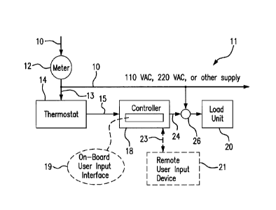
Date Recue/Date Received 2021-09-15
SUMMARY OF THE PRESENT INVENTION
[0004] A feature of the present invention is to provide an electronic
controller which can be
used as an add-on device in HVAC&R systems with thermostat control to
automatically manage
and reduce energy consumption and/or demand consumption in an improved manner
as
compared to operation with thermostat control itself
[0005] Additional features and advantages of the present invention will
be set forth in part
in the description that follows, and in part will be apparent from the
description, or may be
learned by practice of the present invention. The objectives and other
advantages of the present
invention will be realized and attained by means of the elements and
combinations particularly
pointed out in the description and appended claims.
[0006] To achieve these and other advantages, and in accordance with the
purposes of the
present invention, as embodied and broadly described herein, the present
invention relates to an
electronic controller device for automatic control of a heating, ventilating,
air conditioning or
refrigeration (HVAC&R) system, which comprises a) at least one input connector
for
attaching at least one thermostat signal line and at least one output
connector for attaching at
least one signal line for outputting a control signal from the controller
device to a load unit,
wherein the controller device is capable of intercepting a thermostat command
for a load unit
of the HVAC&R system, b) a delayed start controller that is capable of
delaying sending of a
signal to power on a load unit and achieve a selected conditioned space
temperature variation,
and c) a demand regulator controller that is capable of calculating on times
and off times to
obtain a selected electrical demand. The electronic controller can further
include at least one
of an excess time controller and an excess cycle controller as options.
[0007] The present invention further relates to a heating, ventilating,
air conditioning or
refrigeration (HVAC&R) system comprising a heating, ventilating, air
conditioning or
refrigeration unit and the indicated electronic controller device that
intercepts a thermostat
2
Date Recue/Date Received 2021-09-15
control signal of the HVAC&R system and applies an algorithm thereto to
generate an output
control signal for a load unit of the HVAC&R system.
[0008] The present invention further relates to a system for automatic
control of an
HVAC&R system, comprising i) a thermostat, ii) the indicated electronic
controller device,
and iii) at least one of load unit operably connected to a power supply line.
[0009] The present invention further relates to a method for
automatically controlling and
managing energy usage and/or load demand usage and operation of at least one
load unit
powered by electricity in an HVAC&R system, comprising the steps of a)
electrically
connecting the indicated controller device in a control signal line between a
thermostat for a
load unit and an equipment load control switch for the load unit, b)
intercepting at least one
thermostat command from the thermostat for cooling, refrigeration, or heating
at the
controller device, c) applying an algorithm by the electronic controller to
the intercepted
thermostat command to generate an adjusted control signal or allow the OEM
signal as an
output signal, d) outputting the output signal generated by the controller
device to a load unit
switch to control operation of the load unit, and e) estimating the energy
consumption and/or
the demand consumption savings
[0010] It is to be understood that both the foregoing general description
and the following
detailed description are exemplary and explanatory only and are intended to
provide a further
explanation of the present invention, as claimed.
[0011] The accompanying drawings, which are incorporated in and
constitute a part of
this application, illustrate some of the features of the present invention and
together with the
description, serve to explain the principles of the present invention.
3
Date Recue/Date Received 2021-09-15
BRIEF DESCRIPTION OF DRAWINGS
[0012] FIG. 1 is a block/schematic diagram of a HVAC&R system including
an electronic
controller according to an example of the present invention.
[0013] FIG. 2 is a block diagram of a microcontroller of the electronic
controller of FIG. 1
according to an example of the present invention.
[0014] FIGS. 3A and 3B are a flow chart of process control logic of a
process using the
electronic controller for automatically controlling operation of a HVAC&R
system according to
an example of the present invention.
[0015] FIGS. 4A and 4B are flow charts of process control logic for the
operation of an
excess time controller of the electronic controller according to an example of
the present
invention.
[0016] FIG. 5 is a flow chart of process control logic for the operation
of a delayed start
controller of the electronic controller according to an example of the present
invention.
[0017] FIG. 6 is a flow chart of process control logic for the operation
of a demand regulator
controller of the electronic controller according to an example of the present
invention.
[0018] FIGS. 7A and 7B are flow charts of process control logic for the
operation of an
excess cycle controller of the electronic controller according to an example
of the present
invention.
[0019] FIGS. 8A and 8B are flow charts of process control logic for the
limiting of
equipment "delay time, on time, and off time" using the electronic controller
according to an
example of the present invention.
[0020] FIGS. 8C and 8D are flow charts of process control logic for the
operation of a signal
generator of the electronic controller shown in FIGS. 3A and 3B according to
an example of the
present invention.
4
Date Recue/Date Received 2021-09-15
[0021] FIG. 8E is a plot which illustrates channel 1 input (ul) and
channel 1 output (y1)
time histories for the operation of the signal generator of FIGS. 3B, 8C, and
8D according to an
example of the present invention.
[0022] FIG. 9 is an electrical connection diagram for a single stage
cooling application using
the electronic controller according to an example of the present invention,
wherein this
configuration is shown as used when a single thermostat is used to control one
HVAC cooling
device (e.g., a compressor).
[0023] FIG. 10 is an electrical connection diagram for a dual stage
cooling application using
the electronic controller according to an example of the present invention,
wherein this
configuration is shown as used when dual thermostats are used to control two
HVAC cooling
devices (e.g., two compressors).
[0024] FIG. 11 is an electrical connection diagram for a single stage gas
heating application
using the electronic controller according to an example of the present
invention, wherein this
configuration is shown as used when a single thermostat is used to control one
single stage gas
heating device.
[0025] FIG. 12 is an electrical connection diagram for a dual stage gas
heating application
using the electronic controller according to an example of the present
invention, wherein this
configuration is shown as used when dual thermostats are used to control a
dual stage gas heating
device.
[0026] FIG. 13 is an electrical connection diagram for a single stage
electric heating
application using the electronic controller according to an example of the
present invention,
wherein this configuration is shown as used when a single thermostat is used
to control one
single stage electric heating device.
[0027] FIG. 14 is an electrical connection diagram for a dual stage
electric heating
application using the electronic controller according to an example of the
present invention,
Date Recue/Date Received 2021-09-15
wherein this configuration is shown as used when dual thermostats are used to
control a dual
stage electric heating device.
[0028] FIG. 15 is an electrical connection diagram for a cooling with
electric heating
application using the electronic controller according to an example of the
present invention,
wherein this configuration is shown as used when a dual thermostat is used to
control an air
conditioner compressor and an electric heating device.
[0029] FIG. 16 is an electrical connection diagram for a cooling with gas
heating application
using the electronic controller according to an example of the present
invention, wherein this
configuration is shown as used when a dual thermostat is used to control an
air conditioner
compressor and a gas heating device, either forced hot air or hydronic.
[0030] FIG. 17 is an electrical connection diagram for a heat pump with
electric heating
application using the electronic controller according to an example of the
present invention,
wherein this configuration is shown as used when a dual thermostat is used to
control a heat
pump compressor with an auxiliary electric heating device. The "Optional
External Temperature
Switch" is attached to the evaporator discharge to sense when the unit is
operating in cooling or
heating modes.
[0031] FIG. 18 is an electrical connection diagram for a boiler
application using the
electronic controller according to an example of the present invention,
wherein this configuration
is shown as used when a single thermostat is used to control one single stage
boiler heating
device.
[0032] FIG. 19 is a plot showing conditioned space (zone) temperature (
F) over a period
time for a simulated control of a load device in a cooling application of a
HVAC&R system with
an OEM controller (thermostat) and separately with the electronic controller
according to an
example of the present invention.
6
Date Recue/Date Received 2021-09-15
[0033] FIG. 20 is a plot showing the demand (%), which represents energy
consumption,
with respect to demand set point over a period time for the simulated control
indicated for FIG.
19 of the load device of a HVAC&R system with an OEM controller (thermostat)
and separately
with the electronic controller according to an example of the present
invention.
[0034] FIG. 21 is a plot showing the controller off times, on times, and
delay time for the
simulated control indicated for FIG. 19 of the load device of a HVAC&R system
with the
electronic controller according to an example of the present invention.
[0035] FIG. 22 is a plot showing scaled runtime energy consumption for
the simulated
control indicated for FIG. 19 of the load device of a HVAC&R system with an
OEM controller
(thermostat) and separately with the electronic controller according to an
example of the present
invention.
[0036] FIG. 23 is a plot showing maximum allowed and actual equipment
starts per hour
for the simulated control indicated for FIG. 19 of the load device of a HVAC&R
system with
the electronic controller according to an example of the present invention.
[0037] FIG. 24 is a plot showing the energy savings, as a percentage (%)
of the OEM energy
requirements for similar operational time periods, for the simulated control
indicated for FIG.
19 of the load device of a HVAC&R system with the electronic controller
according to an
example of the present invention.
DETAILED DESCRIPTION OF THE PRESENT INVENTION
[0038] The present invention relates in part to a retrofittable
controller add-on device
including integrated programs that can automatically and optimally calculate
and control
execution of duty cycles and cycle time durations for heating equipment,
cooling equipment,
and/or refrigeration equipment that are controlled using duty cycling.
7
Date Recue/Date Received 2021-09-15
[0039] The add-on device comprises an electronic controller which can be
installed in
series in one or more thermostat control signal lines, which is capable of
intercepting
thermostat signals before they reach an intended load unit of an HVAC&R
system. The
electronic controller can apply an algorithm to OEM signals and behavior
thereof to generate
an output signal for the load unit that can replace (or allow) the original
control signal, to
provide more energy efficient operation of the load unit in the system. In
providing this
improvement, the electronic controller can include at least a delayed start
(DS) controller and
a demand regulator (DR) controller, and optionally an excess time (ET)
controller and/or an
excess cycle (EC) controller. These controllers can be implemented as a suite
of computer
programs stored in memory and executable with a microprocessor embodied by the
electronic
controller. In combination, the programs can provide a signal processing
algorithm. The
electronic controller includes signal generation capability to output control
signals from the
controller device to the load unit. The electronic controller can be readily
retrofitted into an
existing HVAC&R system, or incorporated into a new HVAC&R system. The
electronic
controller does not need direct sensor support or line power to function as
designed.
[0040] The delayed start controller included in the electronic controller
can delay or
postpone OEM ON signals from reaching the load unit. This can be done by
applying a factor
or multiplier to the OEM offtime. This results in a longer waiting period
before the load unit
is powered up. It has been found that this manipulation can provide energy
savings without
dramatically changing the temperature profile in the conditioned space. The
electronic
controller can improve demand management as well. The demand regulator
controller
included in the electronic controller can prevent the load unit from running
continuously to
meet demand. The demand regulator controller can periodically turn off the
load unit, which
may tend to increase the time period needed to provide a temperature
adjustment back to the
set point but providing a net reduction in the overall demand needed. This can
be important
8
Date Recue/Date Received 2021-09-15
because the cost of electricity, in commercial and industrial applications, is
based on two
items; (1) the total kW consumption and (2) the Peak kW demand. The total kW
consumption
is (ideally) proportional to the equipment runtime. The Peak kW demand is the
largest average
value of the kW consumption in a 15 or 30 minute interval or window. The Peak
kW demand
value is used to determine how electricity charges are established.
Electricity is charged in
different "declining block rates" of kWh, each of which has a kWh cost
associated with it.
The first block (the one filled first) is the most expensive; the second block
(the one filled
next) is less expensive, and so on. Given a constant total kW consumption, the
total cost of
electricity can be varied by the Peak kW demand value, the smaller the value
of the Peak kW
demand is made, the lower the cost. The indicated demand control regulator of
the electronic
controller of the present invention can be used to lower the value of Peak kW
demand. The
demand regulator controller can reduce the worst case demand while still
providing adequate
cooling or heating of conditioned space as applicable with the controlled load
unit.
[0041] An excess time controller, which is optional, can be included in
the electronic
controller to alter the demand set point in situations where the electronic
controller is in a
continuous run state (i.e., in this state the OEM never turns off). When this
occurs, the
assumption is made that the temperature set point is not being met, so the
demand set point is
increased until the OEM control cycles. If the demand set point is increased
to its maximum
value and the OEM has still not cycled, the demand setpoint is set to 1.0
which effectively
bypasses the controller and relinquishes control to the OEM. The excess cycle
(EC)
controller, which is optional, can be included in the electronic controller to
control the number
of equipment starts per hour so as not to exceed a maximum value by adjusting
the controller
output signal ON and OFF times.
[0042] FIG. 1 shows a HVAC&R system 11 including an electronic controller
18 on
which the indicated delayed start controller, demand regulator controller,
excess time
9
Date Recue/Date Received 2021-09-15
controller, and excess cycle controller programs can reside and from which the
programs can
be executed for signal processing and generation. The electronic controller 18
can be
retrofitted in the system 11 to provide control of at least one HVAC&R load
unit 20 that
provides condition control in a zone 2. Power line 10 passes through utility
meter 12 at the
structure where at least one load unit 20 to be controlled is located. Meter
12 measures usage
and demand of electrical energy at that location. Load unit 20 can be, for
example, an air
conditioner, heat pump, furnace, refrigerator, boiler, or other load unit of a
HVAC&R system.
Operative main power line 10 generally is unconditioned, and supplies
operative power to
load unit 20 via load control switch 26, such as a relay, and typically other
load units and
appliances in the same structure (not shown). The power supply line 10 can be,
for example,
a 110 volts alternating current (VAC), or 220 VAC, or other mains power supply
line
powering the HVAC&R system 11 to be retrofit with the controller 18. The
system 11 to be
retrofit has at least one standard thermostat 14 connected to the HVAC&R load
unit 20.
Thermostat 14 can be connected via line 13 to power line 10. To simplify this
illustration, a
step-down transformer, such as 24 volt transformer, which may be used in
powering the
thermostat from power line 10, is not illustrated in this figure, but is
illustrated in the wiring
diagrams shown in FIGS. 9-18. Electronic controller 18 is not directly powered
from power
line 10, and it does not need to be. Electronic controller 18 is powered by
the thermostat
signaling intended for the load device(s). The electronic controller 18
typically is electrically
dormant (or inactive) or sleeps with respect to its signal processing features
until
receiving/intercepting an ON signal from the thermostat, and then controller
18 becomes
awakened (active) to apply a suite of programs as part of an algorithm such as
shown herein
for signal control processing and control signal generation to the intended
load device(s).
[0043] In
one typical situation, a control signal line 15 of thermostat 14 can transmit
an
AC voltage of 24 volts during the periods when a thermostatic control is, for
example, calling
Date Recue/Date Received 2021-09-15
for cooling from an air conditioning unit (load unit), or heating from an
electric furnace, and
so forth. The control signal would normally activate load control switch 26 in
main power
line 10 to power the load unit 20. That is, in the absence of electronic
controller 18, control
signal line 15 would be in control of opening or closing load unit control
switch 26, and
thereby opening or closing the circuit of operative power line 10 and
controlling the flow of
operative power to load unit 20. The electronic controller 18 is interposed
and installed in the
thermostat control signal line 15 in series at some point between thermostat
14 and the load
unit control switch 26. As shown, thermostat line 15 can be cut and connected
at one cut end
to electronic controller 18. As also shown, the remaining portion of the cut
signal control line,
referenced as line 24, can be connected at one end to electronic controller 18
and at the other
end to load control switch 26.
[0044] The
electronic controller 18 can be physically mounted, for example, in sheet
metal (not shown) near the load unit 20, such as a standard sheet metal
construction enclosure
used with the load unit. Preferably, this tapping of controller 18 into the
control signal line 15
(24) is made as close as practically feasible to the load control switch 26.
Usually it can be
possible to make the connection within the physical confines of the load unit
itself The
connection of electronic controller 18 in the control signal line could be
made, for example,
within the casing containing the compressor unit of a residential air
conditioning unit. For
example, the electronic controller 18 could be mounted in a sheet metal
enclosure that houses
the OEM controls for a compressor of an air conditioning unit as installed on
a slab or
platform near ground level immediately adjoining a home or building supported
by the unit,
or on a rooftop thereof Electronic controller 18 can include on-board user
interface controls
19 and/or can receive control inputs and/or parameter data 23 from a remote
input device 21,
which can be further understood by other descriptions herein that will follow.
The input
device 21 can be "remote" in the sense that it is a physically separate device
from electronic
11
Date Recue/Date Received 2021-09-15
controller 18, which can communicate with the controller, such as via an
attachable/detachable communication wire or cable link or a wireless
communication link.
[0045] In operation, electronic controller 18 receives electrical flow
over control signal
line 15 based on a thermostat control signal intended for powering up the load
unit 20, and
electronic controller 18 can immediately awaken to intercept the thermostat
signal and initiate
its suite of control programs before an output control signal is sent from the
electronic
controller 18 to the load unit switch 26. As indicated, the output control
signal may be a
replacement signal for the OEM signal or the OEM signal, depending on the
outcome of the
running of the controller's algorithm.
[0046] The thermostat 14 preferably is (pre)configured to generate only
an ON/OFF
signal, by which the air conditioner/heat pump compressor, furnace, or other
load unit is
turned on/off. Preferably, the thermostat 14 used in the system 11 is designed
to provide
ON/OFF control at a load unit to turn the load unit completely on or
completely off When
the thermostat is an ON/OFF control device, the thermostat can decide if the
output needs to
be turned on, turned off, or left in its present state. ON/OFF control by an
OEM thermostat
typically comprises selecting a set point, and a native or default OEM
deadband may apply
or may be selected by a user, that straddles the set point. As described
herein, one of the
features of the controller of the present invention relates to a capability of
adjusting and
optimizing deadband type control to increase energy efficiency. A thermostat
that provides
variable speed control is less preferred for use in combination with the
electronic controller.
[0047] The electronic controller 18 does not need direct inputs from a
dedicated
temperature sensor to operate and function as designed. The temperature
sensing capability
of the existing thermostat or thermostats in the system, or systems that
include a remote
sensor(s) that is capable of transmitting such information to the
thermostat(s) for processing
by that unit(s), can be relied on for the systems of the present invention. No
temperature
12
Date Recue/Date Received 2021-09-15
sensor needs be used at all in the HVAC&R systems using the controller,
whether remote
from the thermostat or as sensing component incorporated at the thermostat. A
temperature
signal can be estimated from OEM control signal timing and existing ASHRAE or
similar
data for setpoint and hysteresis temperature values.
[0048]
Though Figure 1 shows a single control line 15 cut and connected from a single
thermostat 14 and connected to the electronic controller 18 for
simplification, it will be
appreciated that in single or dual thermostat configurations, such as shown in
FIGS. 10, 12,
and 14-17, multiple control lines from a single thermostat (e.g., FIGS. 10,
12, 14), or a single
control line from each of multiple thermostats (e.g., FIGS. 15-17) each can be
cut and
separately connected to the electronic controller 18, such as different
respective input pins of
the electronic controller. Where the electronic controller 18 controls more
than one load
device, such as shown in FIGS. 10, 12, and 14-17, an output signal control
line can be
connected at one end to electronic controller 18 and at the other end to the
load control
switches of each load device. For example, although only one load unit 20
under the load
control and management of electronic controller 18 in a single control signal
line is shown in
the HVAC&R system 11 of FIG. 1 for simplification, the HVAC&R system 11 can
include
multiple individual loads under thermostat control, such as, for example,
multiple
compressors, or a compressor unit and a blower, and other similar or diverse
loads, depending
on the configuration. As indicated, the electronic controller of this
invention can be wholly
connected in the control lines of individual subloads of the equipment. In
other words, an air
conditioner may have a separate control line for the subloads of the
compressor unit and the
blower unit. The electronic controller can be used to control either one or
both of these
subloads. The overall power line to all the subloads of the air conditioning
unit is generally
not in any way altered by the electronic controller of this invention.
Further, the usual
13
Date Recue/Date Received 2021-09-15
conventional electrical grounding means is not shown in the schematic diagram
of FIG. 1 as
it is not a matter of particular concern in this invention.
[0049] The electronic controller 18 of FIG. 1, for example, can be
implemented in a stand-
alone configuration or in networked configuration. A stand-alone configuration
can be used,
for example, in a single load unit residential application (e.g., < about 5
ton HVAC&R load
unit). A networked configuration can be used, for example, as part of a
building management
system (BMS) for providing HVAC&R in a larger scale application, such as
higher energy
use/demand residential, commercial or industrial buildings or equipment, and
the like, or, as
a network of electronic controllers, each attached to a dedicated load unit.
[0050] The electronic controller 18 in FIG. 1 includes at least one
microprocessor
operable to receive thermostat input signals, apply the indicated programs to
thermostat
signals received, and transmit an output signal under the command of the
microcontroller to
the HVAC&R load unit to be controlled.
[0051] As shown in FIG. 2, the microcontroller 183 (18 in FIG. 1) can
include, for
example, a microprocessor for storing and executing the indicated the
indicated delayed start
controller, demand regulator controller, excess time controller, and excess
cycle controller
programs, as well as performing data collection function, controlling signal
generation to the
load device(s), and calculating the energy and/or demand savings. As shown in
FIG. 2,
microcontroller 183 can include a microprocessor 1832, a computer-readable
storage medium
1833 shown as incorporating memory 1835, and clock 1834, which all have been
integrated
in the same chip. Microprocessor 1832, also known as a central processing unit
(CPU),
contains the arithmetic, logic, and control circuitry needed to provide the
computing
capability to support the controller functions indicated herein. The memory
1835 of the
computer-readable storage medium 1833 can include non-volatile memory,
volatile memory,
or both. Computer-readable storage medium 1833 can comprise at least one non-
transitory
14
Date Recue/Date Received 2021-09-15
computer usable storage medium. The non-volatile memory can include, for
example, read-
only memory (ROM), or other permanent storage. The volatile memory can
include, for
example, random access memory (RAM), buffers, cache memory, network circuits,
or
combinations thereof The computer-readable storage medium 1833 of the
microcontroller
183 can comprise embedded ROM and RAM. As discussed in connection with FIG. 4
herein,
read/write expansion (flash) memory for the microcontroller also can be
provided.
Programming and data can be stored in computer-readable storage medium 1833
including
memory 1835. Program memory can be provided, for example, for the indicated
delayed start
controller program 1836, demand regulator controller program 1837, excess time
controller
program 1831, and excess cycle controller program 1839, as well as store
menus, operating
instructions and other programming such as indicated herein, parameter values
and the like,
for controlling the controller 18. These programs can be stored in ROM or
other memory. In
combination, the indicated delayed start controller program 1836, demand
regulator
controller program 1837, excess time controller program 1831, and excess cycle
controller
program 1839 provide an integrated control program 1838 residing on controller
18. Data
memory, such as FLASH memory, can be configured with data parameters. Memory
can be
used to store data acquired that is related to the operation of a load device
to be controlled,
such as thermostat command on times and calculated off times. The clock 1834
can be a real
time clock which does not power down with microprocessor features of the
controller during
OFF states. The clock 1834 provides a timing device that can be used for
recording the onset
or termination of the "ON" states. The electronic controller 18 can learn the
thermostat OEM
control behavior by recording "ON" states and their duration in time, and
calculating "OFF"
times. As the signal processing features of the controller are not typically
operational during
"OFF" states of the duty cycle based on the thermostat signals, the time
duration of "OFF"
states can be calculated by recording the time when the controller powers down
as it will
Date Recue/Date Received 2021-09-15
coincide with an OFF state of the duty cycle based on thermostat control, and
recording the
next time when OEM powers up again when intercepting the next successive power
ON signal
sent by the thermostat and intended for the load unit, and calculating the
difference between
these two recorded times as corresponding to the duration of that "OFF time."
This data can
be stored in non-volatile FLASH memory or other memory of the microprocessor.
As
indicated, the clock 1834 can be, for example, a real time digital clock. The
clock 1834 can
be battery powered (e.g., a lithium disc battery, and the like). The
microprocessor 1832,
memory 1833, and clock 1834, can all be integrated and supported on a common
mother
board 1830, or the like, which can be housed in an enclosure (not shown)
having input and
output connection terminal pins, a communication link/interface connector
port(s) (e.g., a
mini-, or micro- or standard-size USB port for receiving a corresponding sized
USB plug),
and the like, which are discussed further with respect to FIGS. 9-18.
[0052]
Microcontroller 183 can be, for example, an 8 bit or 16 bit or larger
microchip
microprocessor including the indicated microprocessor, memory, and clock
components, and
is operable for input and execution of the indicated delayed start controller,
demand regulator
controller, excess time controller, and excess cycle controller programs.
Programmable
microcontrollers can be commercially obtained to which the control programs
indicated
herein can be inputted to provide the desired control. Suitable
microcontrollers in this respect
include those available from commercial vendors, such as Microchip Technology
Inc.,
Chandler, AZ. Examples of commercially available microcontrollers in this
respect include,
for example, the PIC16F87X, PIC16F877, PIC16F877A, PIC16F887, dsPIC30F4012,
and
PIC32MX795F512L-801/PT, by Microchip Technology, Inc.; Analog Devices ADSP
series;
Jermic JN family; National Semiconductor COP8 family; Freescale 68000 family;
Maxim
MAXQ series; Texas Instruments MSP 430 series; and the 8051 family
manufactured by Intel
and others. Additional possible devices include FPGA/ARM and ASIC's. The
delayed start
16
Date Recue/Date Received 2021-09-15
controller, demand regulator controller, excess time controller, and excess
cycle controller
programs indicated herein can be inputted to the respective microcontrollers
using industry
development tools, such as the MPLABX Integrated Development Environment from
Microchip Technology Inc.
[0053] Though the controller 18 is illustrated in FIG. 1 as a stand-alone
unit tapped into
the thermostat signal line 15 (24) to the load unit to be controlled, the
indicated
microelectronics of the controller optionally may be incorporated and
integrated into the
thermostat unit or a Building Management System (BMS). An algorithm
incorporating the
delayed start controller, the demand regulator controller, the excess time
controller, the excess
cycle controller, and other indicated control programs and features of the
electronic device
can be added to native thermostat signal control software of the thermostat,
or can be added
to Building Management System (BMS) software where a BMS provides control to
the load
unit or units of the HVAC&R, eliminating a need for a physically separate
electronic
controller device. In the combined thermostat/electronic controller
arrangement, the
interception of the OEM thermostat signal and processing thereof by the
controller
microelectronics can occur at the modified thermostat unit without the need
for a physically
separate microelectronic controller being tapped into the thermostat signal
line 15 (24)
between the thermostat and the load unit to be controlled.
[0054] FIGS. 3A and 3B show process control logic 100 for the use of an
electronic
controller 100 of the present invention for automatically controlling
operation of a HVAC&R
system. Residing within the controller are (1) four controllers, (2) a limits
module, and (3) a
control signal generator, and other features indicated in FIGS. 3-8. As
indicated, the
controller prevents OEM thermostat signals from directly reaching the intended
load unit(s)
in the HVAC&R system, and intercepts those signals for learning and processing
into
optimized output signals for the intended load unit(s). Signal acquisition is
time based. As
17
Date Recue/Date Received 2021-09-15
indicated, OEM ON and OFF times can be determined by the electronic
controller. The
electronic controller embodies an algorithm that computes a triplet or triad
of time outputs,
which are delay time, on time, and off time with respect to control signals
outputted to the
load unit(s). These signals can be converted into a time-history signal in the
"Signal
Generator" block in FIG. 3B. The output signals can be stored and processed as
binary output
that has values of 0 or 1, such used for output yl and y2 shown in FIG. 3B.
[0055] Readable inputs to the electronic controller include: 1) OEM
inputs 105: OEM
channel 1 (chl)(ul: compressor or heater), OEM channel 2 (ch2)(u2; blower or
compressor2
or heater2), and dry contacts for possible integration with a building
management system
(BMS) (all are 1/0 = On/Off); 2) calculated values 106: FPF1 and FPF2 (first
pass flags for
OEM chi and OEM ch2, chi-tOff0EM and ch2-tOff0EM (OEM chi and ch2 OFF times);
and 3) parameters 107: configuration parameters inputted to the controller
from a service
tool or the like, and stored in memory (e.g., FLASH memory). The input channel
1 (ul) and
channel 2 (u2) values can correspond to read OEM inputs for two different load
units in the
system. In systems with thermostat control provided for a single load unit,
the OEM input
for one of the channel 1 or channel 2 can be used. For calculated values 106,
the OEM chi
and ch2 OFF times can be initialized to zero for the first time the electronic
controller is
activated, and then calculated thereafter based on the OEM duty cycle history
that is
encountered. The electronic controller can be configured through its parameter
setting 107 to
control a compressor, furnace, boiler, or other HVAC&R load units.
[0056] The electronic controller 100 can implement a delayed start
controller 101,
demand regulator controller 102, excess time controller 103, and excess cycle
controller 104.
These programs can be loaded into memory in the electronic controller, such as
ROM, during
assembly of the electronic controller or some other time before use. The
demand regulator
controller 102 and excess time controller are non-optional, and the delayed
start controller
18
Date Recue/Date Received 2021-09-15
101 and excess cycle controller 104 can be optional. There is a sequence of
implementation
of these controllers. The delayed start controller 101, if used, is
implemented first, and then
the demand regulator controller 102 and excess time controller are implemented
in parallel,
but combine output for processing at the S¨>V box 112. This is followed by the
excess cycle
controller 104, if included, and the limits module 108, and ultimately the
signal generator
109. The outputs of the controller are: 1) yl and y2 (chi and ch2 outputs; 1/0
= On/Off) to
the compressor or heater, and blower, respectively, and 2) 4 LED signals. The
output y 1
corresponds with a channel 1 control signal for the compressor or heater and
output y2
corresponds to channel 2 output for the blower. Write outputs and write LED's
are indicated
at 110 and 111. The algorithm can be executed at regular intervals of one
times (x) a second,
such as 2x/second, 3x/second, 4x/second, or 5x/second or other rates during
time periods
when the controller is awake.
[0057] FIGS.
4A and 4B are flow charts of process control logic 120A, 120B, and 120C
for the operation of the optionally-usable excess time controller of the
electronic controller.
Control logic 120A and 120B are shown in FIG. 4A, and control logic 120C is
shown in FIG.
4C. As shown, the "Ontime" value generated by the process control logic 120B
and unloaded
parameters in control logic 120A as shown in FIG. 4A are used as input in the
process flow
logic 120C shown in FIG. 4B that continues from the control logic shown in
FIG. 4A, in
addition to other indicated calculated values and/or parameters. The excess
Time (ET)
Controller can alter the DemandSetpoint in situations where the controller is
in a continuous
run state (in this state the OEM never turns off). When this occurs, the
assumption is made
that the temperature setpoint is not being met, so the DemandSetpoint is
increased until the
OEM control cycles. If the DemandSetpoint is increased to its maximum value
and the OEM
has still not cycled, the DemandSetpoint remains at 1.0 which effectively
bypasses the
controller and allows the OEM to control. This function has 3 parameters:
WaitTime = Initial
19
Date Recue/Date Received 2021-09-15
run-on time, no action is taken during this time, and HorizonTime & MaxDemand:
if after
"WaitTime" seconds, the OEM has not cycled, the DemandSetpoint is increased
linearly from
its initial setpoint value, "DemandSetpointl" by the value: (time after
WaitTime)*(MaxDemand - DemandSetpoint1)/(HorizonTime - WaitTime). This
controller
can linearly increase DemandSetpoint to 1, if OEM does not cycle, and set
DemandSetpoint
= 1 until next OEM cycle occurs.
[0058] FIG.
5 is a flow chart of process control logic 130A and 130B for the operation of
the delayed start controller of the electronic controller according to an
example of the present
invention. As shown, the "Factor Setpoint" and "NativeTimeDelay" values of the
process
control logic 130A are used as inputs in the process flow logic 130B as shown
in FIG. 5, in
addition to other indicated calculated values and/or parameters. The delayed
Start (DS)
Controller calculates a delay time (tDelayPace). For example, most OEM
thermostats will
control to within +/- 1 degree Fahrenheit ( F) of their setpoint, this means
their deadband
(Tdb) is 2 degrees Fahrenheit. If an OEM thermostat setpoint is set to 70 F,
the zone
temperature will range from 69 to 71 F. Tdb = 2 F (with the setpoint = 70
F), the OEM
will control zone temperature from 69 to 71 F. If the Factor Setpoint is set
to 1.75 the pace
will control to a deadband = 1.75*2 = 3.5 F from 69 F to 72.5 F. The time
required for the
2 F deadband to be traversed is measured as "tOffZone" (the OFF time of the
zone). If the
deadband is defined as dT1 and the Off time as ti, dT1/t1 can be written as
equal (=) constant
(approximately). If the off time value is doubled to t2 = 2*tl, the deadband
will also be
approximately doubled, dT2=2*dT1 for the ratio to remain constant = dT2/t2 =
dT1/t1.
Factor is defined as dT2/dT1 = Factor = t2/t1, which can be written as
Factor*t1 = t2 or,
subtracting ti from both sides Factor*t1 - ti = t2 - ti. The value t2-t1 is
the additional time
delay defined as "tDelayPace" and is solved as: tDelayPace = ti *(Factor - 1).
The Native
Time Delay indicated in FIG. 5, is a time delay between the electronic call
for heating or
Date Recue/Date Received 2021-09-15
cooling and the time the equipment cycles on. It is sometimes present in OEM
controls. If it
is not known for the existing system, it can be determined by measuring the
time from when
a thermostat clicks on until the load unit turns on or by initializing using
an estimate and
adjusting the value as needed.
[0059] The tDelayPace value calculated by the Delayed Start controller
can also be used
to control the blower. The blower control can be turned on when the compressor
is first turned
on and remains on until the thermostat turns it off This method prevents
unwanted cycling
of the blower during an OEM controller cycle but takes advantage of the
initial delay as a
savings mechanism.
[0060] FIG. 6 is a flow chart of process control logic 140A and 140B for
the operation of
the demand regulator controller of the electronic controller according to an
example of the
present invention. As shown, the "Demand Setpoint", "ShortCycleTime", and
"CompressorConsumption fraction" values generated by the process control logic
140A are
used as inputs in the process flow logic 140B as shown in FIG. 6, in addition
to other indicated
calculated values and/or parameters. The demand regulator controller can
calculate a
controller-output "on" time value, a "tOnPace value," to achieve a Demand
Setpoint. The
Demand Regulator (DR) Controller calculates the controller-output ON time
given the Duty
Cycle (Demand Setpoint) and the controller OFF time (tOffPace =
ShortCycleTime) by
solving the following equation for tOnPace:
[0061] Demand Setpoint = (tonPace/(tOnPace +
tOffPace))*CompressorConsumption,
fraction + 1 - CompressorConsumption, fraction).The blower consumption is
defined as (1 -
CompressorConsumption, fraction). The rightmost term assumes the blower is ON
full time
for this calculation (hence the presence of the (1 - CompressorConsumption,
fraction). This
function also will not allow tOnPace to drop below a value that would cause
the Demand
21
Date Recue/Date Received 2021-09-15
Setpoint to be less than the blower consumption fraction (1 -
CompressorConsumption,
fraction). If this occurs, tOnPace is set to 0 which effectively turns off the
compressor
[0062] As indicated, the Demand Regulator (DR) Controller can adjust the
controller-output
"on" (tOnPace) and "off' (tOffPace) times sent to the load unit such that a
desired electrical
demand can be achieved. Theoretically, electrical demand typically is
calculated as the total
"on" time during a 15 minute interval. The DR controller can estimate the
"worst case" demand
which is the condition where the Pace controller is continuously cycling
during the entire 15
minute interval. The worst case demand becomes more accurate as the load
increases and less
accurate at lower loads, however, it always estimates the worst case demand
which is greater
than the actual demand. The DR controller fixes the tOffPace value to the
short cycle time (e.g.,
typically 3 ¨4 minutes) and can adjust the tOnPace to meet the desired demand.
[0063] FIGS. 7A and 7B are flow charts of process control logic 150A,
150B, and 150C
for the operation of an optionally-usable excess cycle controller of the
electronic controller
according to an example of the present invention. Control logic 150A and 150B
are shown in
FIG. 7A, and control logic 150C is shown in FIG. 7B. As shown, the
"EquipmentStartsPerHourMAX" value of the process control logic 150A is used in
the
process control logic 150B, and the "tOnpace" value generated by the process
control logic
150B and the "DemandSetpoint" and "CompressorConsumption Factor" values
generated by
the process control logic 150A are used as an input in the process flow logic
150C shown in
FIG. 7B that continues from the control logic shown in FIG. 7A, in addition to
other indicated
calculated values and/or parameters. The excess cycle controller can increase
tOnPace to meet
equipment starts per hour maximum (MAX). The excess cycle (EC) controller
controls the
number of equipment starts per hour so as not to exceed a maximum (MAX) value
by
adjusting tOnPace and tOffPace. First, the excess cycle controller determines
if the number
of equipment starts per hour exceeds MAX. If it does, then tOnPace is
increased until the
22
Date Recue/Date Received 2021-09-15
Actual Equipment Starts per Hour < MAX value. If, after increase of tOnPace,
the Demand
Setpoint is still not being achieved, tOffPace is then increased until
DemandActual (equal to
tOnPace/(tOnPace + tOffPace)) < DemandSetpoint. Thus, if tOnPace has been
modified and
the Demand is not being met, tOffPace is then further adjusted to meet the
Demand setpoint.
[0064] FIG. 8A and 8B are flow charts of process control logic 170A and
170B,
respectively, for the limiting of equipment starts using the electronic
controller according to
an example of the present invention. As shown, the "Mode of Operation"
generated by the
process control logic 170A in FIG. 8A is used as an input in the process flow
logic 170B
shown in FIG. 8B, in addition to other indicated calculated values and/or
parameters. This
function applies minimum (MIN) and maximum (MAX) limits to tOnPace, tOffPace,
and
tDelayPace. The DryContactInput may be used to select the Mode of Operation
defined as
follows: 1 = Extend (excessive heating or cooling required); 0 = Normal. The
DryContactInput may be used to select whether Normal or Extend settings are
used for
limiting the tDelay, tOn, and tOff ("Pace") values controlled by the
electronic controller.
DryContactEnabled: 1/0 = Enable/ Disable the dry contact input.
DryContactInput = 1/0 =
Open circuit/ Closed circuit. DCInvert allows reversing of the polarity of the
DryContactInput
signal. When DCInvert = "OFF" = 0, the mode of operation is set to the
DryContactInput
value. When DryContactInput = 1, extend Settings are used. When
DryContactInput = 0,
normal settings are used. When DCInvert = "ON" = 1, the mode of operation is
set to the not
(DryContactInput) value. When DryContactInput = 1, normal settings are used.
When
DryContactInput = 0, extend settings are used.
[0065] As examples, in a heating application:
[0066] In a heating application, a 55 F snap sensor on OAT can be used to
detect
excessive heating requirements, wherein the sensor closes at temperatures <55
F and opens
23
Date Recue/Date Received 2021-09-15
at temperatures > 55 F; and DryContactInput = 0/1 (closed/open =
extend/normal) = <55 F/
>55 F = Extend values/ Normal values; and set DCInvert = OFF.
[0067] In a cooling Application: an 85 F snap sensor on OAT can be used
to detect
excessive cooling requirements; the sensor closes at temperatures > 85 F and
opens at
temperatures < 85 F; DryContactInput = 1/0 (open/closed = normal/extend) = <
85 F/ >85 F
= Normal values/ Extend values; and set DCInvert = ON.
[0068] In a heat pump application: a 55 F snap sensor on the evaporator
line can be used
to detect if the heat pump is in cooling or heating operation; the sensor
closes at temperatures
<55 F (for cooling) and opens at temperatures > 55 F (for heating);
DryContactInput = 0/1
(closed/open = normal/extend) = <55 F/ >55 F; and extend values are used for
heating and
normal values are used for cooling; and set DCInvert = OFF.
[0069] FIGS. 8C and 8D are flow charts of process control logic 180A and
180B,
respectively, for the operation of the Signal Generator 109 of the electronic
controller shown
in FIG. 3B. As shown, the "PaceCycleTime" value generated by the process
control logic
180A in FIG. 8C is used as an input in the process flow logic 180B shown in
FIG. 8D that
continues from the control logic shown in FIG. 8C, in addition to other
indicated calculated
values and/or parameters. For simplicity, in FIGS. 8C-8D, only one of the two
channels is
shown (channel 1 with input ul and output yl). The second channel 2 (channel 2
with input
u2 and output y2) can be processed similarly as shown for channel 1. The
Signal Generator
109 can function to create a binary modulated control signal as a function of
the time triplet,
(tD el ayP acel, tOnP acel, and tOffP ac el), calculated by the indicated DS
and DR controllers.
The Signal Generator can operate as follows: when the OEM control signals
transitions from
OFF to ON, the First Pass Flag (FPF1) is pulsed which begins running the timer
function
"u0EM ON time timer" in FIG. 8C to measure the "OnTime" of the OEM control
signal. As
soon as the "OnTime" exceeds the "tDelayPacel" value, the "cycle timer"
function begins
24
Date Recue/Date Received 2021-09-15
calculating the "PaceCycleTime". The "PaceCycleTime" is reset to 0 each time
it exceeds the
desired cycle period "tOnPacel + tOffPacel". The "y1" control signal is ON
when the
"OnTime" > "tDelayPacel" AND "PaceCycleTime" < "tOnPacel", otherwise it is
OFF.
[0070] The functions of the various controllers and modules and other
features of the
process control logic shown in any of FIGS. 3, 4A-B, 5, 6, 7A-B, and 8A-D can
be
implemented using software that is executable with the indicated
microprocessor of the
electronic controller.
[0071] Referring to FIG. 8E, to illustrate the operation of the Signal
Generator 109 shown
in FIGS. 3, 8C, and 8D, an OEM signal, ul, is applied to the Signal Generator
in an example
using the following settings: tDelayPacel = 20 seconds, tOnPacel = 10 seconds,
and
tOffPacel = 20 seconds. The ul and yl time histories are presented in FIG. 8E.
For a given
cycle of the ul signal, the yl signal evolves initially with a tDelayPacel =
20 seconds
followed by a repeating sequence of 10 seconds ON (tOnPacel) followed by 20
seconds OFF
(tOffPacel). The yl signal turns off when the ul signal turns off The ul
signal in the above
diagram evolves with an ON time that increases between cycles, that is the
reason that there
are only 2 yl cycles in the first ul cycle and 3 yl cycles thereafter.
[0072] The wiring terminations for each often examples of installation
configurations are
presented below with reference made to FIGS. 9-18. For all of these
illustrations in FIGS. 9-
18, the electronic controller 1018 provides two independent control channels
that may be
wired to support different equipment configurations. Referring to the first
pin module 1001,
the first channel 1001A comprises one of pins 1-3, and the second channel
1001B comprises
one of pins 4-6 thereof Output lines to the load unit(s) are shown as
extending from one of
pins 4-6. The first channel 1001A and second channel 1001B are only
specifically identified
in FIG. 9, and it will be understood that the same indicated pin assignments
for these channels
can apply in similar pin module 1001 as shown in the electronic controller
1018 in each of
Date Recue/Date Received 2021-09-15
FIGS. 10-18. In addition, the controller provides a separate "dry contact"
input channel that
may be used for remote control of the controller, such as by an existing BMS
system.
Referring to the second pin module 1010, pins 1-2 thereof can be used for this
dry contact
input module. A communication port 1020 is shown in these figures as a mini-
USB port (e.g.,
a camera size USB port) but is not limited thereto. A service tool (not shown)
can be used to
import/input parameters, and the like into the electronic controller 1018 by
making a
communication link with the controller via port 1020. The electronic
controller 1018 can
have the indicated delayed start controller, demand regulator controller,
excess time
controller, and excess cycle controller programs preloaded into the controller
on-board
memory during its assembly and before installation in the field.
[0073] FIG. 9 shows an electrical connection diagram 1000 for a single
stage cooling
application using an electronic controller according to an example of the
present invention.
The wiring termination for this configuration is presented in the figure. This
configuration
can be used when a single air conditioner thermostat is used to control one
HVAC cooling
device (a compressor). This configuration also supports thermostats that
provide a manual
switch to select either heating or cooling operation. The compressor can be a
compressor
suitable for use in vapor-compression cooling/refrigeration systems. The
compressor can
include an electric motor (not shown), used to drive the compressor. The
electric motor itself
can be a conventional electric motor or other suitable electric motor used or
useful for driving
such load units.
[0074] The thermostat can be deployed at some point in a building and
senses the
temperature of the ambient air and if it is higher than the comfort setting
which has been
selected, sends a signal to activate the air conditioning unit. As indicated,
in the present
invention, the controller intercepts the thermostat signal, which powers up
the electronic
controller to process the signal according to its programmed algorithm before
sending a
26
Date Recue/Date Received 2021-09-15
controller-processed output signal to the load unit. The air conditioning unit
typically
comprises the compressor, and a condenser and evaporator connecting with each
other in a
closed refrigerant system (not shown). The refrigeration cycle itself is well
known (e.g., see,
U.S. Patent No. 4,094,166). Basically, gaseous refrigerant is delivered from
the compressor
to the condenser coil where it gives up heat and then is passed through an
expansion valve to
the evaporator coil where it absorbs heat from the circulating air which is
passed thereover
by the evaporator fan. When the thermostat senses that the ambient air has
been cooled to the
selected level, the thermostat goes to an off state to turn off the
compressor, evaporator fan
and condenser fan until the ambient temperature has again reached the level
where further
cooling is necessary. As indicated, the electronic controller of the present
invention goes to
sleep when the thermostat stops signaling the load unit, until the next power
on signal is sent
by the thermostat to the same load unit which, as indicated, will be
intercepted by the
electronic controller which powers up the electronic controller to process the
signal according
to its programmed algorithm before sending a controller-processed output
signal to the load
unit. As indicated, a deadband typically is applied to the control temperature
setting at the
thermostat, which deadband effectively can be modified by the electronic
controller to
increase energy savings in a controlled manner.
[0075] FIG. 10 shows an electrical connection diagram 1100 for a dual
stage cooling
application using an electronic controller according to an example of the
present invention.
The wiring termination for this configuration is presented in the figure. This
configuration
can be used when a single thermostat is used to control two HVAC cooling
devices, which
are two compressors in this example. This configuration also supports
thermostats that
provide a manual switch to select either heating or cooling operation.
[0076] FIG. 11 shows an electrical connection diagram 1200 for a single
stage gas heating
application using an electronic controller according to an example of the
present invention.
27
Date Recue/Date Received 2021-09-15
The wiring termination for this configuration is presented in the figure. This
configuration
can be used when a single thermostat is used to control one single stage gas
heating device.
This configuration also supports thermostats that provide a manual switch to
select either
heating or cooling operation.
[0077] FIG. 12 shows an electrical connection diagram 1300 for a dual
stage gas heating
application using an electronic controller according to an example of the
present invention.
The wiring termination for this configuration is presented in the figure. This
configuration
can be used when a single thermostat is used to control a dual stage gas
heating device. This
configuration also supports thermostats that provide a manual switch to select
either heating
or cooling operation.
[0078] FIG. 13 shows an electrical connection diagram 1400 for a single
stage electric
heating application using an electronic controller according to an example of
the present
invention. The wiring termination for this configuration is presented in the
figure. This
configuration can be used when a single thermostat is used to control one
single stage electric
heating device. This configuration also supports thermostats that provide a
manual switch to
select either heating or cooling operation.
[0079] FIG. 14 shows an electrical connection diagram 1500 for a dual
stage electric
heating application using an electronic controller according to an example of
the present
invention. The wiring termination for this configuration is presented in the
figure. This
configuration can be used when a single thermostat is used to control a dual
stage electric
heating device. This configuration is used when a single thermostat is used to
control a dual
stage electric heating device. This configuration also supports thermostats
that provide a
manual switch to select either heating or cooling operation.
[0080] FIG. 15 shows an electrical connection diagram 1600 for a cooling
with electric
heating application using an electronic controller according to an example of
the present
28
Date Recue/Date Received 2021-09-15
invention. The wiring termination for this configuration is presented in the
figure. This
configuration can be used when a dual thermostat is used to control an air
conditioner
compressor and an electric heating device. This configuration also supports
thermostats that
provide a manual switch to select either heating or cooling operation. The
controller 1018
may be controlled remotely with an input from a BMS or other similar system
(not shown).
If this feature is required, the "dry contact" input 1010 is used. FIG. 15
also includes the
wiring terminations for connecting an optional external temperature sensor to
the dry contact
inputs.
[0081] FIG. 16 shows an electrical connection diagram 1700 for a cooling
with gas
heating application using an electronic controller according to an example of
the present
invention. The wiring termination for this configuration is presented in the
figure. This
configuration can be used when a dual thermostat is used to control an air
conditioner
compressor and a gas heating device. This configuration also supports
thermostats that
provide a manual switch to select either heating or cooling operation. The
controller 1018
may be controlled remotely in this configuration with an input from a BMS or
other similar
system (not shown). As with the configuration of FIG. 15, if this feature is
required, the "dry
contact" input is used. FIG. 16 includes the wiring terminations for
connecting an optional
external temperature sensor to the dry contact inputs.
[0082] FIG. 17 is an electrical connection diagram 1800 for a heat pump
with electric
heating application using an electronic controller according to an example of
the present
invention. The wiring termination for this configuration is presented in the
figure. This
configuration can be used when a dual thermostat is used to control a heat
pump compressor
with an auxiliary electric heating device. This configuration also supports
thermostats that
provide a manual switch to select either heating or cooling operation. The
controller 1018
may be controlled remotely in this configuration with an input from a BMS or
other similar
29
Date Recue/Date Received 2021-09-15
system (not shown). As with the configurations of FIGS. 15 and 16, if this
feature is required,
the "dry contact" input is used. FIG. 17 includes the wiring terminations for
connecting an
optional external temperature sensor to the dry contact inputs.
[0083] FIG.
18 shows an electrical connection diagram 1900 for a boiler application using
an electronic controller according to an example of the present invention. The
wiring
termination for this configuration is presented in the figure. This
configuration can be used
when a single thermostat is used to control one single stage boiler heating
device.
[0084] In
these manners, for example, an electronic controller having the indicated
delayed start controller, demand regulator controller, excess time controller,
and excess cycle
controller programs is operable to intercept and process a thermostat's
control signal with an
algorithm that can automatically generate enhanced control signals. Amongst
other benefits
and advantages, existing HVAC&R systems, for example, can embody the present
controller
such as illustrated herein to improve energy consumption and reduce energy
costs of heating,
cooling, and refrigeration equipment.
[0085] The
present invention includes the following aspects/embodiments/features in any
order and/or in any combination:
1. The
present invention relates to an electronic controller device for automatic
control
of a heating, ventilating, air conditioning or refrigeration (HVAC&R) system,
comprising:
at least one input connector for attaching at least one thermostat signal line
and at least
one output connector for attaching at least one signal line for outputting a
control signal from
the controller device to a load unit, wherein the controller device is capable
of intercepting a
thermostat command for a load unit of the HVAC&R system;
a delayed start controller that is capable of delaying sending of a signal to
power on a
load unit and achieve a selected conditioned space temperature variation; and
Date Recue/Date Received 2021-09-15
a demand regulator controller that is capable of calculating on times and off
times to
obtain a selected electrical demand.
2. The electronic controller device of any preceding or following
embodiment/feature/aspect, wherein the controller device is capable of
intercepting a
thermostat command for at least one of a compressor, blower, or heater.
3. The electronic controller device of any preceding or following
embodiment/feature/aspect, comprising a computer-readable storage medium, a
programmable microprocessor, and a real time clock, wherein the delayed start
controller and
demand regulator controller are stored as programs in the computer-readable
storage medium
and are executable on the microprocessor, and the controller device operable
to record OEM
power ON times with reference made to the real time clock.
4. The electronic controller device of any preceding or following
embodiment/feature/aspect, wherein the delayed start controller that is
capable of delaying
sending of a signal to start a load unit wherein an OEM temperature deadband
setting of a
thermostat is multiplied by a selected factor having a numerical value of 1 or
more to obtain
a zone temperature deadband which replaces the OEM temperature deadband.
5. The electronic controller device of any preceding or following
embodiment/feature/aspect, wherein the demand regulator controller is capable
of setting
controller off time values to a fixed value and adjusting controller on time
values to satisfy a
selected electrical demand set point between 100% and 0% demand.
6. The electronic controller device of any preceding or following
embodiment/feature/aspect, further comprising at least one of an excess time
controller and
an excess cycle controller.
7. The electronic controller device any preceding or following
embodiment/feature/aspect, further comprising a signal generator capable of
generating a
31
Date Recue/Date Received 2021-09-15
control signal based at least in part on application of a signal processing
algorithm to a
thermostat command intercepted by the electronic controller device, as
performed at least in
part with the delayed start controller and demand regulator controller.
8. The present invention relates to a heating, ventilating, air
conditioning or refrigeration
(HVAC&R) system comprising a heating, ventilating, air conditioning or
refrigeration unit
and the electronic controller device of embodiment 1 that intercepts a
thermostat control
signal of the HVAC&R system and applies an algorithm thereto to generate an
output control
signal for a load unit of the HVAC&R system.
9. The present invention relates to a system for automatic control of an
HVAC&R
system, comprising:
a thermostat;
an electronic controller device, and
at least one of load unit operably connected to a power supply line, wherein
the electronic controller device comprising a) at least one input connector
for attaching
at least one thermostat signal line and at least one output connector for
attaching at least one
signal line for outputting a control signal from the controller device to a
load unit, wherein
the controller device is capable of intercepting a thermostat command for a
load unit of the
HVAC&R system, b) a delayed start controller that is capable of delaying
sending of a signal
to power on a load unit and achieve a selected conditioned space temperature
variation, and
c) a demand regulator controller that is capable of calculating on times and
off times to obtain
a selected electrical demand.
10. The system of any preceding or following embodiment/feature/aspect,
wherein
multiple load units of the HVAC&R system are concurrently controlled with the
electronic
controller.
32
Date Recue/Date Received 2021-09-15
11. The system of any preceding or following embodiment/feature/aspect,
further
comprising a signal generator capable of generating a control signal based at
least in part on
application of a signal processing algorithm to a thermostat command
intercepted by the
electronic controller device, as performed at least in part with the delayed
start controller and
demand regulator controller.
12. The system of any preceding or following embodiment/feature/aspect,
wherein an
algorithm incorporating at least the delayed start controller and the demand
regulator
controller is added to thermostat software of the thermostat, or Building
Management System
(BMS) software where a BMS provides control to the at least one load unit.
13. The present invention relates to a method for automatically controlling
and managing
power usage and/or load demand and operation of at least one load unit powered
by electricity
in an HVAC&R system, comprising the steps of:
electrically connecting a controller device in a control signal line between a
thermostat
for a load unit and an equipment load control switch for the load unit,
wherein the controller
device comprising a) at least one input connector for attaching at least one
thermostat signal
line and at least one output connector for attaching at least one signal line
for outputting a
control signal from the controller device to a load unit, wherein the
controller device is
capable of intercepting a thermostat command for a load unit of the HVAC&R
system, b) a
delayed start controller that is capable of delaying sending of a signal to
power on a load unit
and achieve a selected conditioned space temperature variation, and c) a
demand regulator
controller that is capable of calculating on times and off times to obtain a
selected electrical
demand;
intercepting at least one thermostat command from the thermostat for cooling,
refrigeration, or heating at the controller device;
33
Date Recue/Date Received 2021-09-15
applying an algorithm by the electronic controller to the intercepted
thermostat
command to generate an adjusted control signal or allow the OEM signal as an
output signal;
outputting the output signal generated by the controller device to a load unit
switch to
control operation of the load unit; and
e) estimating the energy consumption and/or the demand consumption savings.
14. The method of any preceding or following embodiment/feature/aspect,
wherein the
load unit of the HVAC&R system comprises a compressor, a blower, a gas heater,
an electric
heater, or a boiler.
15. The method of any preceding or following embodiment/feature/aspect,
wherein
multiple load units of the HVAC&R system are concurrently controlled with the
electronic
controller.
[0086] The present invention can include any combination of these various
features or
embodiments above and/or below as set forth in sentences and/or paragraphs.
Any
combination of disclosed features herein is considered part of the present
invention and no
limitation is intended with respect to combinable features.
[0087] The present invention will be further clarified by the following
examples, which are
intended to be exemplary of the present invention.
Example 1
[0088] Performance was evaluated as follows. A simulation of an operation
of a single stage
cooling system, wherein a single thermostat is used to control one compressor,
such as shown in
FIG. 9, with the electronic controller, and without the electronic controller
(OEM control alone),
was performed. The simulation was performed on a computer model that was
developed using
VisSim software, obtained from Visual Solutions of Westford, MA, USA. The
developed
program was adapted to simulate operation of the electronic controller that
applies the process
34
Date Recue/Date Received 2021-09-15
control logic shown in FIGS. 3-8 herein, and the OEM thermostat control
operating alone
(without the electronic controller). The developed model was based in part on
actual data
obtained from operation of the same equipment in the indicated single stage
cooling
configuration and with the OEM thermostat alone in the field. The simulation
model is
calibrated to agree with field data.
[0089] The ability of the electronic controller to obey the Factor
Setpoint is presented in
terms of temperature regulation in the history plot shown in FIG. 19. Factor
Setpoint was
initially set at 2.7, Demand Setpoint at 0.8, and Equipment Starts Per Hour to
7. A Factor
setting of 2.7 means that the target Zone Temperature should vary across a
deadband of 2.7*2
degrees = 5.4 degrees, during this time the simulated Zone Temperature varies
between 68
and 71.75 degrees or 3.75 degrees deadband which is acceptable. At time 10000
seconds, the
Factor Setpoint was reduced to 1.5 (which corresponds to a Zone temperature
variation of 3
degrees, the simulated variation was from 68 to 71 degrees or 3 degrees), then
increased back
to 2.7 at time 20000 seconds and then decreased back to 1.5 at time 60000
seconds. These
temperature degrees all can refer to F.
[0090] The ability of the electronic controller to obey the Demand
Setpoint is presented
in terms of temperature regulation in the history plot shown in FIG. 20.
Demand Setpoint
was decreased to 60% at time 40000 seconds and then increased back to 80% at
time 50000
seconds. Demand setpoint tracking is acceptable, however, between times 65000
and 80000
seconds, the Demand Setpoint could not be achieved because the "ON" and "OFF"
times were
in a limited state of operation (these limits are configurable but are in
place to prevent damage
to the equipment). Also, there is an adverse effect on temperature as the
Demand Setpoint is
decreased as seen in the upper right time history plot between times 40000 and
50000 seconds.
As the Demand Setpoint is decreased, the equipment will run less frequently
and the
conditioned space temperature will increase.
Date Recue/Date Received 2021-09-15
[0091] Fig. 20 presents the demand tracking performance of the DR
controller.
[0092] The plot shown in FIG. 21 presents the time delay (tDelayPace)
calculated by the DS
controller, and "on" and "off' times (tOnPace and tOffPace) calculated by the
DR controller as
the Demand Setpoint and Factor Setpoint were varied
[0093] The equipment starts per hour is shown in the time history shown
in FIG. 23.
Starts per hour is fixed at 7 until time 65000 seconds, where it is decreased
to 3 and then back
to 6 at time 80000 seconds. The controller is designed to not exceed the
Maximum allowed
equipment starts per hour.
[0094] FIG. 22 shows the energy consumption of the compressor and blower
under control
by this invention compared to an OEM control working on identical equipment in
identical load
conditions.
[0095] FIG. 23 shows the compressor starts per hour and is self-
explanatory.
[0096] FIG. 24 is a plot showing the energy savings, as a normalized
percentage (%) of
the OEM energy requirements for similar operational time periods, for the
simulated control
indicated for FIG. 19 of the load device of a HVAC&R system with an electronic
controller
according to an example of the present invention. The energy savings for this
illustration are
about 20%.
[0097] When an amount, concentration, or other value or parameter is
given as either a
range, preferred range, or a list of upper preferable values and lower
preferable values, this is to
be understood as specifically disclosing all ranges formed from any pair of
any upper range limit
or preferred value and any lower range limit or preferred value, regardless of
whether ranges are
separately disclosed. Where a range of numerical values is recited herein,
unless otherwise
stated, the range is intended to include the endpoints thereof, and all
integers and fractions within
the range. It is not intended that the scope of the invention be limited to
the specific values
recited when defining a range.
36
Date Recue/Date Received 2021-09-15
[0098] Other
embodiments of the present invention will be apparent to those skilled in the
art from consideration of the present specification and practice of the
present invention disclosed
herein. It is intended that the present specification and examples be
considered as exemplary
only with a true scope and spirit of the invention being indicated by the
following claims and
equivalents thereof
37
Date Recue/Date Received 2021-09-15