Note: Descriptions are shown in the official language in which they were submitted.
CA 02910301 2015-10-27
BALE LOADING TRAILER WITH AUTOMATIC BALE MOVEMENT
This disclosure relates to the field of agricultural equipment and in
particular a trailer for
loading and transporting large cylindrical bales of crop material.
BACKGROUND
Hay, straw and like agricultural products are commonly harvested from the
field by
cutting same and baling into large cylindrical bales. Various bale moving
equipment has
been developed to collect these bales and transport same to a storage
location.
For example United States Patent Number 8,967,934 to Palmlund et al. discloses
a trailer
with an elongated bale supporting frame mounted on wheels with a bale lifting
assembly
mounted on one side. The large cylindrical bales are lifted from the ground by
a fork
assembly and placed onto the front end of the bale supporting frame. A bale
shifting
assembly pushes rearward on the front bale to move the row of accumulating
bales
sequentially rearward as they are loaded until the bale supporting frame is
filled.
Palmlund also discusses generally the possibility of automating the process of
lifting the
bale and moving the bale rearward to make room for the next bale.
The trailer of Palmlund carries a single row of bales, while United States
Patent Number
6,935,827 to Delaurier discloses a trailer with two side-by-side rows of
bales. Delaurier
has a fork assembly on each side and a pair of side-by-side bale supporting
frames
mounted on wheels. The bales rest on a conveyor chain under each row of bales,
and
each conveyor chain is operated to move the accumulating bales sequentially
rearward as
they are loaded until the corresponding bale supporting frame is filled.
1
CA 02910301 2015-10-27
Similarly Canadian Patent 2,300,006 to Rempel discloses a trailer a pair of
side-by-side
bale supporting frames mounted. The frames comprise right and left rails, and
a
conveyor chain running along the top of each rail. The bales rest on the right
and left
conveyor chains and are moved sequentially rearward by operating the conveyor
chains.
SUMMARY OF THE INVENTION
The present disclosure provides a bale loading trailer apparatus that
overcomes problems
in the prior art.
In a first embodiment the present disclosure provides a bale loading trailer
apparatus for
loading cylindrical bales. The apparatus comprises a bale supporting frame
mounted on
wheels, with a hitch at a front end thereof adapted for connection to a towing
vehicle. A
fork assembly is pivotally mounted beside a front end of the bale supporting
frame and is
configured to engage a bale resting on a ground surface when in a lowered
position, and
to disengage the bale when the fork assembly is in a raised position such that
the bale
moves onto the front end of the bale supporting frame. A hydraulic cylinder is
operative
to move the fork assembly between the lowered position and the raised
position. A
conveyor chain assembly extends along substantially a length of the bale
supporting
frame, and is configured such that loaded bales rest on the conveyor chain
assembly, and
move along the bale supporting frame in concert with the conveyor chain
assembly. A
hydraulic motor drive is operative to move the conveyor chain assembly. A
hydraulic
valve circuit connects the hydraulic cylinder and the hydraulic motor drive
such that as
the fork assembly moves from the raised position to the lowered position, l
ydraulic fluid
flows from the hydraulic cylinder through the hydraulic motor drive and causes
the
conveyor chain assembly to move a cycle distance in a rearward direction, and
such that
as the fork assembly moves from the lowered position to the raised position,
the conveyor
chain assembly remains substantially stationary.
2
CA 02910301 2015-10-27
In a second embodiment the present disclosure provides a method of loading
cylindrical
bales. The method comprises mounting a bale supporting frame on wheels, and
connecting a hitch at a front end thereof to a towing vehicle; pivotally
mounting a fork
assembly beside a front end of the bale supporting frame and configuring a
hydraulic
cylinder to move the fork assembly between a lowered position and a raised
position;
maneuvering the towing vehicle with the fork assembly in the lowered position
such that
the fork assembly engages a first bale resting on a ground surface; operating
the hydraulic
cylinder to move the fork assembly to the raised position where the fork
assembly
disengages the first bale and the first bale moves onto the front end of the
bale supporting
frame and rests on a conveyor chain assembly extending along substantially a
length of
the bale supporting frame; wherein the hydraulic cylinder is connected to a
hydraulic
motor drive operative to move the conveyor chain assembly, the connection
configured
such that as the fork assembly moves from the raised position to the lowered
position,
hydraulic fluid flows from the hydraulic cylinder through the hydraulic motor
drive, and
such that as the fork assembly moves from the lowered position to the raised
position, the
conveyor chain assembly remains substantially stationary; moving the fork
assembly
from the raised position to the lowered position such that hydraulic fluid
flows from the
hydraulic cylinder through the hydraulic motor drive and causes the conveyor
chain
assembly, and any bales resting thereon, to move a cycle distance in a
rearward direction;
maneuvering the towing vehicle with the fork assembly in the lowered position
to engage
the fork assembly with a second bale resting on a ground surface; and
operating the
hydraulic cylinder to move the fork assembly to the raised position such that
the second
bale moves onto the front end of the bale supporting frame and rests on the
conveyor
chain assembly forward of the first bale.
The bale loading trailer apparatus and method of the present disclosure
reduces demands
on the operator by providing a simple and economical configuration for
automatically
3
CA 02910301 2015-10-27
moving a freshly loaded bale rearwards by rotating the hydraulic motor driving
the chain
assembly as the fork assembly is lowered after placing a bale on the bale
supporting
frame. Hydraulic fluid flowing from the hydraulic cylinder that operates the
fork
assembly is directed through the hydraulic motor or motors as the fork
assembly is
lowered to a position ready to pick up the next bale. The amount of hydraulic
fluid
flowing through the hydraulic motor or motors is selected to move the bale
rearward the
desired distance corresponding to the length of the bale.
Thus the operator is freed from the need to move the bale rearward and is able
to
concentrate on finding the next bale to pick up and maneuver the bale loading
trailer
apparatus to the required position to do so. Thus operator fatigue and the
risk of error
and the resulting lost time and possible damage to equipment is reduced.
DESCRIPTION OF THE DRAWINGS
While the invention is claimed in the concluding portions hereof, preferred
embodiments
are provided in the accompanying detailed description which may be best
understood in
conjunction with the accompanying diagrams where like parts in each of the
several
diagrams are labeled with like numbers, and where:
Fig. 1 is a schematic top view of an embodiment of the bale loading trailer
apparatus of
the present disclosure for loading cylindrical bales that has right and left
conveyor
chains mounted on corresponding right and left rails of the bale supporting
frame, and
showing the fork assembly in the lowered position;
Fig. 2 is a schematic front view of the embodiment of Fig. 1 showing the fork
assembly in the lowered position;
4
CA 02910301 2015-10-27
Fig. 3 is a schematic front view of the embodiment of Fig. 1 showing the fork
assembly in the raised position;
Figs. 4A and 4B schematically illustrate the flow of hydraulic fluid as the
fork
assembly moves from the raised position to the lowered position and the
conveyor
chain assembly moves rearward driven by the hydraulic motors;
Fig. 5 is a top view of an alternate embodiment of the bale loading trailer
apparatus of
the present disclosure for loading cylindrical bales that has a single
conveyor chain
mounted in the middle of a load bed substantially equidistant between right
and left
frame bars;
Fig. 6 is a schematic front view of the embodiment Fig. 5 with a bale resting
on the
conveyor chain;
Fig. 7 is a schematic diagram of the flow of hydraulic fluid through a flow
control that
is operative to adjust the cycle distance to correspond to a bale length;
Figs 8A ¨ 8D show the operation of the apparatus of Fig. 1 loading a plurality
of bales;
Fig. 9 is a top view of an alternate embodiment of the bale loading trailer
apparatus of
the present disclosure for loading cylindrical bales that includes side-by-
side bale
supporting frames for loading side-by-side rows of bales on the apparatus.
DETAILED DESCRIPTION OF THE ILLUSTRATED EMBODIMENTS
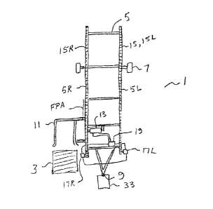
Figs. 1 ¨ 3 schematically illustrate an embodiment of a bale loading trailer
apparatus 1 of
the present disclosure for loading cylindrical bales 3. The apparatus 1
comprises a bale
5
CA 02910301 2015-10-27
supporting frame 5 mounted on wheels 7, with a hitch 9 at a front end thereof
adapted for
connection to a towing vehicle, typically a tractor.
A fork assembly 11 is pivotally mounted about fork pivot axis FPA beside a
front end of
the bale supporting frame 5 and is configured to engage a bale 3 resting on a
ground
surface when in a lowered position illustrated in Figs. 1 and 2, and to
disengage the bale
3 when the fork assembly 11 is in a raised position shown in Figs. 3 and 8A
such that the
bale 3 rolls down and moves onto the front end of the bale supporting frame 5.
A
hydraulic cylinder 13 is operative to move the fork assembly 11 between the
lowered
position and the raised position.
A conveyor chain assembly 15 extends along the length of the bale supporting
frame 5
and is configured such that loaded bales 3 rest on the conveyor chain assembly
15, and
move along the bale supporting frame 5 in concert with the conveyor chain
assembly 15,
and a hydraulic motor drive 17 is operative to move the conveyor chain
assembly 15.
Figs. 8A ¨ 8D schematically illustrate the operation of the apparatus 1
picking bales 3
from the ground and moving same onto the bale supporting frame 5. In a typical
baling
operation the bales 3 have substantially the same bale length BL.
Fig. 8A shows the fork assembly 11 in the raised position having just
deposited a first
bale 3A on the bale supporting frame 5 such that same rests on the conveyor
chain
assembly 15. Fig. 88 shows that the fork assembly 11 has moved down from the
raised
position of Fig. 8A to the lowered position, and the first bale 3A has moved
rearward by
a cycle distance CD which equal to the bale length BL. In Fig. 8B the
apparatus 1 is
moving in operating travel direction T and the fork assembly 11 is approaching
a second
bale 3B. Fig. 8C shows the fork assembly 11 has engaged the second bale 3B and
moved
to the raised position and the second bale 3B has rolled off the fork assembly
11 onto the
6
CA 02910301 2015-10-27
bale supporting frame 5, just in front of the first bale 3A. Fig. 8D shows
that the fork
assembly 11 has again moved down from the raised position of Fig. 8C to the
lowered
position, and the first and second bales 3A, 3B have moved rearward by the
cycle
distance CD, leaving room for the next bale 3C.
The rearward movement of the bales 3 is accomplished automatically when the
fork
assembly moves from the raised position to the lowered position by providing a
hydraulic
valve circuit 19, schematically illustrated in Fig. 4, that connects the
hydraulic cylinder
13 and the hydraulic motor drive 17 such that as the hydraulic cylinder 13
moves the fork
assembly 11 from the raised position to the lowered position, hydraulic fluid
flows from
the hydraulic cylinder 13 through the hydraulic motor drive 17 and causes the
conveyor
chain assembly 15, and any bales 3 resting thereon, to move a cycle distance
CD in a
rearward direction, and such that as the fork assembly 11 moves from the
lowered
position to the raised position, the conveyor chain assembly 15 remains
substantially
stationary.
In the illustrated apparatus 1 the bale supporting frame 5 comprises right and
left rails 5R,
5L, and the conveyor chain assembly 15 comprises corresponding right and left
conveyor
chains 15R, 15L extending along top sides of the corresponding right and left
rails 5R,
5L. The hydraulic motor drive 17 comprises right and left hydraulic motors
17R, 17L
operative to move the corresponding right and left conveyor chains 15R, 15L,
and the
loaded bales 3 rest on the right and left conveyor chains 15R, 15L.
In the illustrated apparatus the hydraulic cylinder 13 and fork assembly 11
are configured
such that as the pressurized hydraulic fluid source 21 directs pressurized
hydraulic fluid
into a first port 23A of the hydraulic cylinder 13, as schematically
illustrated in Fig. 4A,
the piston 25 moves in extending direction ED and the hydraulic cylinder 13
extends to
move the fork assembly 11 from the lowered position to the raised position as
seen in
Figs. 2 and 3. The hydraulic fluid forced from the second port 23B is directed
through
7
CA 02910301 2015-10-27
the hydraulic valve circuit 19 directly back to the hydraulic fluid source 21,
bypassing the
hydraulic motor drive 17 such that the hydraulic motors 17R, I 7L remain
stationary
while the fork assembly moves up from the lowered position to the raised
position.
The pressurized hydraulic fluid source 21 directs pressurized hydraulic fluid
into a
second port 23B of the hydraulic cylinder 13 which then moves the piston 25 in
retracting
direction RD to move the fork assembly 11 from the raised position to the
lowered
position. The hydraulic fluid source 21, hydraulic cylinder 13, and hydraulic
motors
17R, 17L are schematically illustrated in Figs. 4A and 4B connected by the
hydraulic
valve circuit 19.
As the hydraulic fluid source 21 directs hydraulic fluid into the second port
23B the
hydraulic cylinder 13 retracts and the fork assembly 11 moves from the raised
position to
the lowered position. The piston 25 moves in retracting direction RD forcing
hydraulic
fluid to flow from the first port 23A of the hydraulic cylinder 13. The
hydraulic valve
circuit 19 is configured to direct flow out of the first port 23A into one of
the right and
left hydraulic motors, here illustrated as left hydraulic motor 17L, and then
from that
hydraulic motor 17L into the other hydraulic motor 17R and then back to the
hydraulic
fluid source 21, as schematically illustrated in Fig. 4B. Thus hydraulic
motors 17R, 17L
rotate at the same speed and the same amount moving the conveyor chains 15R,
15L
evenly rearward, and the hydraulic motor drive 17 drives the conveyor chain
assembly 15
as the fork assembly 11 moves from the raised position to the lowered position
and the
bales 3 move rearward by the cycle distance CD.
In the apparatus 1 the hydraulic cylinder 13 retracts to move the fork
assembly from the
raised position to the lowered position. It is well known in the art to
configure such a
linkage such that the hydraulic cylinder extends when lowering the fork
assembly from
8
CA 02910301 2015-10-27
the raised position to the lowered position. In such a configuration the first
and second
ports 23a, 23b would simply be on opposite ends of the hydraulic cylinder.
Figs. 5 and 6 schematically illustrated an alternate embodiment of a bale
loading trailer
apparatus 101 of the present disclosure for loading cylindrical bales 103.
Here the bale
supporting frame 105 comprises right and left frame bars 105R, 105L and the
conveyor
chain assembly comprises a single conveyor chain 115 extending along a load
bed 127
below and substantially midway between the right and left bars 105R, 105L. The
hydraulic motor drive here comprises a single hydraulic motor 117. The right
and left
frame bars 105R, 105L are configured to maintain the loaded bales 3 resting on
the
conveyor chain 115. The hydraulic valve circuit is the same as that shown in
Figs 4A, 4B
but with only a single hydraulic motor 17.
Fig. 7 schematic illustrates a flow control 29 operative to adjust the cycle
distance CD to
correspond to a variety of bale lengths BL up to a maximum bale length. The
cycle
distance CD is proportional to the amount of rotation of the hydraulic motor
drive, and
the amount of rotation of the hydraulic motor drive 17 is dependent on the
amount of
hydraulic fluid flowing from the first port 23A of the hydraulic cylinder to
the hydraulic
motor drive 17. As the fork assembly moves from the raised position to the
lowered
position pressurized hydraulic fluid from the hydraulic fluid source 21 is
directed into the
second port 23B of the hydraulic cylinder 13 and a hydraulic fluid flow is
discharged
from the first port 23A of the hydraulic cylinder 13. The flow control 29 is
operative to
direct a selected portion PI of the hydraulic fluid flow to the hydraulic
motor drive 17
and a remaining portion P2 of the hydraulic fluid flow back to the hydraulic
fluid source
21. A knob 31 on the flow control 29 allows the operator to adjust the
selected portion
P1 of hydraulic fluid flow to achieve the desired cycle distance to suit a
particular bale
length.
9
CA 02910301 2015-10-27
The maximum bale length that can be achieved will depend on the amount of
hydraulic
fluid available in the hydraulic cylinder 13 that will be pushed through the
hydraulic
motor drive, and the amount of rotation of the hydraulic motors 17 for a given
amount of
hydraulic fluid flow will depend on the size of the hydraulic motor drive.
Thus the
diameter and a stroke of the hydraulic cylinder 13, and the size of the
hydraulic motor
drive 17, are selected such that a volume of the hydraulic fluid flow is
sufficient to
provide a cycle distance that is at least equal to the maximum bale length
desired.
Fig. 9 schematically illustrates an alternate embodiment of a bale loading
trailer
apparatus 201 of the present disclosure for loading cylindrical bales. The
apparatus 201
is essentially two of the apparatuses 1 mounted side-by-side on a frame with a
hitch at the
front end thereof for attaching to a towing vehicle. Right and left bale
supporting frames
205R, 205L are mounted on wheels 207. Conveyor chain assemblies 215R, 215L are
mounted on the rails of the corresponding bale supporting frames 205R, 205L,
and right
and left fork assemblies 211R, 211L are mounted adjacent to front ends of the
corresponding bale supporting frames 205R, 205L, and right and left hydraulic
cylinders
213R, 213L and hydraulic motor drives 217R, 217L are connected by
corresponding right
and left hydraulic valve circuits 219R, 219L.
The present disclosure also provides a method of loading cylindrical bales 3.
The method
comprises mounting a bale supporting frame 5 on wheels 7, and connecting a
hitch 9 at a
front end thereof to a towing vehicle 33; pivotally mounting a fork assembly
11 beside a
front end of the bale supporting frame 5 and configuring a hydraulic cylinder
13 to move
the fork assembly 11 between a lowered position and a raised position;
maneuvering the
towing vehicle 33 with the fork assembly 11 in the lowered position such that
the fork
assembly 11 engages a first bale 3A resting on a ground surface; operating the
hydraulic
cylinder 13 to move the fork assembly 11 to the raised position where the fork
assembly
11 disengages the first bale 3A and the first bale 3A moves onto the front end
of the bale
CA 02910301 2015-10-27
supporting frame 5 and rests on a conveyor chain assembly 15 extending along
substantially a length of the bale supporting frame 5; wherein the hydraulic
cylinder 13
is connected to a hydraulic motor drive 17 operative to move the conveyor
chain
assembly 15, the connection configured such that as the fork assembly 11 moves
from the
raised position to the lowered position, hydraulic fluid flows from the
hydraulic cylinder
13 through the hydraulic motor drive 17, and such that as the fork assembly 11
moves
from the lowered position to the raised position, the conveyor chain assembly
15 remains
substantially stationary; moving the fork assembly 5 from the raised position
to the
lowered position such that hydraulic fluid flows from the hydraulic cylinder
13 through
the hydraulic motor drive 17 and causes the conveyor chain assembly 15, and
any bales 3
resting thereon, to move a cycle distance CD in a rearward direction;
maneuvering the
towing vehicle 33 with the fork assembly 11 in the lowered position to engage
the fork
assembly 11 with a second bale 3B resting on a ground surface; and operating
the
hydraulic cylinder 13 to move the fork assembly 11 to the raised position such
that the
second bale 3A moves onto the front end of the bale supporting frzune 5 and
rests on the
conveyor chain assembly 15 forward of the first bale 3A.
The bale loading trailer apparatus 1 of the present disclosure reduces demands
on the
operator by providing a simple and economical configuration for automatically
moving a
freshly loaded bale rearwards by rotating the hydraulic motor 17 driving the
chain
assembly 15 as the fork assembly 11 is lowered after placing a bale on the
bale
supporting frame 5. Hydraulic fluid flowing from the hydraulic cylinder 13
that operates
the fork assembly 11 is directed through the hydraulic motor or motors 17 as
the fork
assembly 11 is lowered to a position ready to pick up the next bale. The
amount of
hydraulic fluid flowing through the hydraulic motor or motors 17 is selected
to move the
bale rearward the desired distance corresponding to the length of the bale.
11
CA 02910301 2015-10-27
Thus the operator is freed from the need to move the bale rearward and is able
to
concentrate on finding the next bale to pick up and maneuver the bale loading
trailer
apparatus 1 to the required position to do so. Thus operator fatigue and the
risk of error
and the resulting lost time and possible damage to equipment is reduced.
The foregoing is considered as illustrative only of the principles of the
invention.
Further, since numerous changes and modifications will readily occur to those
skilled in
the art, it is not desired to limit the invention to the exact construction
and operation
shown and described, and accordingly, all such suitable changes or
modifications in
structure or operation which may be resorted to are intended to fall within
the scope of
the claimed invention.
12