Note: Descriptions are shown in the official language in which they were submitted.
CA 02910361 2015-10-27
ARRANGEMENT OF MULTI-CHANNEL BIPOLAR ELECTRODE
ZONES TO MINIMIZE LEAKAGE AND EDGE EFFECTS
BACKGROUND
[0001] The human body has a number of internal body lumens or cavities
located within, such as
the differing parts of the gastro-intestinal tract, many of which have an
inner lining or layer. Body
lumens may include, for example, the esophagus, small and large intestines,
stomach, remnant after
bariatric surgery, rectum and anus. These inner linings may be susceptible to
disease. In some
cases, different ablation techniques may be utilized with respect to the inner
lining in order to
prevent the spread of disease to otherwise healthy tissue located nearby.
[0002] Ablation devices may include multiple distinct areas or zones that
may be selectively
activated or deactivated during an ablation procedure. However, in certain
circumstances, when a
particular zone is activated, current may leak from that zone to one or more
of the other zones of
the ablation device. The problem of current leakage may result in insufficient
energy being delivered
to the intended zone, which may cause insufficient ablation of the target
tissue.
[0003] Therefore, there may be a need for systems, devices and methods that
may overcome the
above or other disadvantages of known systems, devices, and methods.
SUMMARY
[0004] The described features generally relate to methods, systems, and
devices for minimizing
various leakage effects of multi-zone ablation devices. A device for treatment
of tissue may include
an ablation structure with a plurality of bipolar electrode zones. Each
electrode zone may include a
positive channel and a negative channel. According to various embodiments
described herein, the
channels and electrode zones may be arranged to reduce the current losses
associated with in-zone
and adjacent-zone leakage effects.
[0005] An ablation device for treatment of tissue is provided in accordance
with various
embodiments. The ablation device may include an ablation structure including a
plurality of bipolar
electrode zones. Each electrode zone may include an in-zone channel pair that
comprises a positive
channel and a negative channel. Furthermore, the ablation structure may be
configured such that,
for any adjacent electrode zone pair including a first electrode zone and a
second electrode zone
adjacent to the first electrode zone, the positive channel of the first
electrode zone is electrically
distinct from the positive channel of the second electrode zone, and the
negative channel of the first
electrode zone is electrically distinct from the negative channel of the
second electrode zone.
1
CA 02610361 2015-10-27
Moreover, the ablation structure comprises a total number of electrically
distinct channels that is
less than twice a total number of the plurality of electrode zones in various
embodiments.
[0006] In certain embodiments, the ablation structure is further
configured such that every
shared-positive-channel electrode zone pair comprises a negative channel pair
that is electrically
distinct from the negative channel pair of every other shared-positive-channel
electrode zone pair.
According to some embodiments, the ablation structure is further configured
such that every in-
zone channel pair is electrically distinct from every adjacent-zone channel
pair.
[0007] Moreover, the ablation structure is further configured such that
each electrode zone
comprises an in-zone channel pair that is electrically distinct from the in-
zone channel pair of every
other electrode zone in various embodiments.
[0008] According to some embodiments, each of the electrode zones are
configured to be
selectively enabled or disabled. For example, each of the electrode zones may
be configured to be
selectively enabled by supplying alternating current to the in-zone channel
pair of each electrode
zone. In various embodiments, the plurality of electrode zones of an ablation
structure are aligned
adjacent to each other. Furthermore, the plurality of electrode zones may be
equal in width.
[0009] In various embodiments described, an ablation device may further
include a catheter, an
expansion member coupled with a distal portion of the catheter, an ablation
structure support
coupled with the ablation structure, wherein the ablation structure and the
ablation structure
support are configured to at least partially unfurl or furl around the
expansion member as the
expansion member expands or contracts.
[0010] In some embodiments, the expansion member is a balloon. The balloon
may be made
from a semi-compliant material in some embodiments.
[0011] In a particular embodiment, an ablation device comprises six
electrode zones wherein a
first electrode zone comprises an in-zone channel pair including a first
positive channel and a first
negative channel, a second electrode zone adjacent to the first electrode zone
comprises an in-zone
channel pair including a second positive channel and a second negative
channel, and a third
electrode zone adjacent to the second electrode zone comprises an in-zone
channel pair including a
third positive channel and a third negative channel. Additionally, a fourth
electrode zone adjacent to
the third electrode zone comprises an in-zone channel pair including the first
positive channel and
the second negative channel, a fifth electrode zone adjacent to the fourth
electrode zone comprises
an in-zone channel pair including the third positive channel and the first
negative channel, and a
2
CA 02910361 2015-10-27
sixth electrode zone adjacent to the fifth electrode zone comprises an in-zone
channel pair including
the second positive channel and the third negative channel.
[0012] In another particular embodiment described including six electrode
zones, a first electrode
zone comprises an in-zone channel pair including a first positive channel and
a first negative channel,
a second electrode zone adjacent to the first electrode zone comprises an in-
zone channel pair
including a second positive channel and a second negative channel, and a third
electrode zone
adjacent to the second electrode zone comprises an in-zone channel pair
including a third positive
channel and a third negative channel. Moreover, a fourth electrode zone
adjacent to the third
electrode zone comprises an in-zone channel pair including the first positive
channel and the second
negative channel, a fifth electrode zone adjacent to the fourth electrode zone
comprises an in-zone
channel pair comprising the second positive channel and the third negative
channel, and a sixth
electrode zone adjacent to the fifth electrode zone comprises an in-zone
channel pair comprising the
third positive channel and a fourth negative channel.
[0013] In yet another particular embodiment described, an ablation
structure comprises seven
electrode zones. According to various embodiments, a first electrode zone
comprises an in-zone
channel pair comprising a first positive channel and a first negative channel,
a second electrode zone
adjacent to the first electrode zone comprises an in-zone channel pair
comprising a second positive
channel and a second negative channel, a third electrode zone adjacent to the
second electrode
zone comprises an in-zone channel pair comprising a third positive channel and
the first negative
channel, and a fourth electrode zone adjacent to the third electrode zone
comprises an in-zone
channel pair comprising the second positive channel and a third negative
channel. Moreover, a fifth
electrode zone adjacent to the fourth electrode zone comprises an in-zone
channel pair comprising a
fourth positive channel and the first negative channel, a sixth electrode zone
adjacent to the fifth
electrode zone comprises an in-zone channel pair comprising a fifth positive
channel and the second
negative channel, and a seventh electrode zone adjacent to the sixth electrode
zone comprises an
in-zone channel pair comprising the first positive channel and the third
negative channel.
[0014] In another particular embodiment of an ablation structure including
seven electrode
zones, a first electrode zone comprises an in-zone channel pair comprising a
first positive channel
and a first negative channel, a second electrode zone adjacent to the first
electrode zone comprises
an in-zone channel pair comprising a second positive channel and a second
negative channel, a third
electrode zone adjacent to the second electrode zone comprises an in-zone
channel pair comprising
a third positive channel and the first negative channel, and a fourth
electrode zone adjacent to the
third electrode zone comprises an in-zone channel pair comprising the second
positive channel and a
3
CA 02910361 2015-10-27
third negative channel. Additionally, a fifth electrode zone adjacent to the
fourth electrode zone
comprises an in-zone channel pair comprising a fourth positive channel and the
first negative
channel, a sixth electrode zone adjacent to the fifth electrode zone comprises
an in-zone channel
pair comprising a fifth positive channel and the third negative channel, and a
seventh electrode zone
adjacent to the sixth electrode zone comprises an in-zone channel pair
comprising the fourth
positive channel and the second negative channel.
[0015] According to various embodiments, a method of designing an ablation
structure with
multiple bipolar electrode zones for treating tissue is provided. The method
may include providing
each electrode zone with an in-zone channel pair comprising a positive channel
and a negative
channel, and limiting a total number of electrically distinct channels of the
ablation structure such
that the total number of electrically distinct channels is less than twice a
total number of the
plurality of electrode zones. Moreover, the method may also include arranging
the positive channels
of each electrode zone such that, the positive channel of any electrode zone
is electrically distinct
from the positive channel of any adjacent electrode zone and arranging the
negative channels of
each electrode zone such that the negative channel of any electrode zone is
electrically distinct from
the negative channel of any adjacent electrode zone.
[0016] In some embodiments, the method further comprises arranging the
positive and negative
channels of each electrode zone such that every shared-positive-channel
electrode zone pair
comprises a negative channel pair that is electrically distinct from the
negative channel pair of every
other shared-positive-channel electrode zone pair.
[0017] Moreover, in certain embodiments, the method further comprises
arranging the positive
and negative channels of each electrode zone such that every in-zone channel
pair is electrically
distinct from every adjacent-zone channel pair.
[0018] Certain embodiments of the present disclosure may include some,
all, or none of the
above advantages or features. One or more other technical advantages or
features may be readily
apparent to those skilled in the art from the figures, descriptions, and
claims included herein.
Moreover, while specific advantages or features have been enumerated above,
various
embodiments may include all, some, or none of the enumerated advantages or
features.
[0019] Further scope of the applicability of the described methods and
apparatuses will become
apparent from the following detailed description, claims, and drawings. The
detailed description
and specific examples are given by way of illustration only, since various
changes and modifications
within the spirit and scope of the description will become apparent to those
skilled in the art.
4
1
CA 02910361 2015-10-27
BRIEF DESCRIPTION OF THE DRAWINGS
[0020] A further understanding of the nature and advantages of the embodiments
may be
realized by reference to the following drawings. In the appended figures,
similar components or
features may have the same reference label. Further, various components of the
same type may be
distinguished by following the reference label by a dash and a second label
that distinguishes among
the similar components. If only the first reference label is used in the
specification, the description is
applicable to any one of the similar components having the same first
reference label irrespective of
the second reference label.
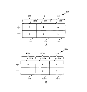
[0021] FIG. 1A is a schematic diagram of an ablation structure with
three electrode zones in
accordance with various embodiments;
[0022] FIG. 1B is a schematic diagram of an ablation structure with
three electrode zones in
accordance with various embodiments;
[0023] FIG. 2 is a schematic diagram of an ablation structure with
three electrode zones in
accordance with various embodiments;
[0024] FIG. 3 is a schematic diagram of an ablation structure with five
electrode zones in
accordance with various embodiments;
[0025] FIG. 4 is a schematic diagram of an ablation structure with
six electrode zones in
accordance with various embodiments;
[0026] FIG. 5 is a schematic diagram of an ablation structure with
six electrode zones in
accordance with various embodiments;
[0027] FIG. 6 is a schematic diagram of an ablation structure with
seven electrode zones in
accordance with various embodiments;
[0028] FIG. 7 is a schematic diagram of an ablation structure with
seven electrode zones in
accordance with various embodiments;
[0029] FIG. 8 is a schematic diagram of an ablation structure with seven
electrode zones in
accordance with various embodiments;
[0030] FIG. 9 is a schematic diagram of an ablation system for
delivering treatment to a target
treatment area including components configured in accordance with various
embodiments;
5
CA 02910361 2015-10-27
[0031] FIG. 10 is a flow diagram of a method for designing an ablation
structure in accordance
with various embodiments;
[0032] FIG. 11 is a flow diagram of a method for designing an ablation
structure in accordance
with various embodiments; and
[0033] FIG. 12 is a flow diagram of a method for designing an ablation
structure in accordance
with various embodiments.
DETAILED DESCRIPTION
[0034] To treat certain conditions within a body lumen, such as the
gastrointestinal tract, area-
based ablation may be used to ablate specific segments of tissue. For various
reasons, an area-
based ablation device may be divided into multiple distinct areas or zones
that are selectively
operable. One such reason for dividing an area-based ablation device into
multiple zones may be to
maintain a high degree of control over which areas of tissue are being ablated
at any given time
during an ablation procedure. Another reason is that a typical power supply
may not be capable of
providing sufficient energy to the entire ablation structure simultaneously.
However, in certain
circumstances, current from an activated zone may leak or travel along an
alternate path to one or
more of the other zones of the ablation device. The problem of current leakage
may be the result of
the physical arrangement and proximity of the different zones with respect to
each other, or the
arrangement and number of electrically distinct electrical channels that power
the zones, or some
combination of both. In any case, this leakage may reduce the amount of energy
delivered to the
target zone, which may result in insufficient ablation of the target tissue.
[0035] As described herein, a distinct area or zone of an area-based
ablation device capable of
ablating a corresponding area of tissue is referred to as an electrode zone.
In accordance with
various embodiments, each of the multiple electrode zones of an area-based
ablation device may be
powered by one or more electrical channels. As used herein, a channel is an
electrical connection
which may be activated or deactivated by selectively supplying current from a
power source. For
example, a channel may be an individual wire connecting an electrode zone to a
power source. In
some embodiments, the electrode zones of an ablation device are bipolar
electrode zones
comprising two electrical channels each. Therefore, if each electrode zone
comprised two
electrically distinct channels, then the total number of electrically distinct
channels would be twice
the number of electrode zones.
6
1
CA 02910361 2015-10-27
[0036] However, in accordance with various embodiments described
herein, the total number of
distinct electrical channels may be reduced to less than twice the total
number of electrode zones of
an ablation device. For example, instead of ten distinct electrical channels,
a five-zone ablation
device may have nine or eight or even fewer distinct electrical channels.
Reducing the number of
distinct electrical channels of an ablation device may advantageously reduce
the size and
manufacturing cost of the ablation device. However, if an ablation device has
a total number of
distinct electrical channels that is less than twice the total number of
electrode zones, then the
device may be susceptible to various leakage and edge effects. As used herein,
leakage effects
refers to the delivery of power outside of the intended treatment area or
zone, which decreases the
power delivered to the intended treatment area or zone. Edge effects refers to
the phenomena
which change the behavior of energy delivery on the peripheries of electrode
zones, whether or not
adjacent to another electrode zone. Therefore, in accordance with various
embodiments described
herein, the electrical channels of a multi-zone ablation device may be
arranged and configured so as
to reduce potential leakage effects, edge effects, or any combination of the
two.
[0037] Referring to FIG. 1A, a schematic diagram of an ablation structure
100 is shown in
accordance with various embodiments. The ablation structure 100 is illustrated
with three electrode
zones, 105, 110, and 115. Each of the electrode zones 105, 110, 115 are
examples of bipolar
electrode zones. Accordingly, each electrode zone 105, 110, 115 comprises two
electrical channels.
For example, zone 105 comprises channels 120 and 125, zone 110 comprises
channels 130 and 135,
and zone 115 comprises channels 140 and 145. The two channels of each
electrode zone may be
referred to as a "positive channel" and a "negative channel." However, in
certain embodiments, the
energy delivered to the ablation structure is non-grounded alternating current
(AC) power. In such
embodiments, the positive and negative channels of each electrode zone are
functionally equivalent.
Nevertheless, for labeling purposes, one channel of a bipolar electrode zone
is referred to as the
positive channel and the other channel is referred to as the negative channel.
As used with
reference to the figures described herein, the positive channels are labeled
with letters (e.g., A, B, C)
and the negative channels are labeled with numbers (1, 2, 3).
[0038] At this point, it is important to distinguish between the
labeling conventions of the
numeric identifiers of the channels (e.g., 120 and 125) and the names of the
channels (e.g., A and 1).
As used herein, a channel name (e.g., A) denotes a channel that is
electrically distinct from all other
channels with a different name on the ablation device. For example the
positive channel A is
electrically distinct from the positive channel B, and both channels A and B
are electrically distinct
from negative channel 1. An electrically distinct channel means that the
channel is not directly
7
CA 02910361 2015-10-27
electrically connected to any of the other channels. For example channel A and
channel B may be
completely separate wires. On the other hand, the numeric identifiers, such as
120 and 125, merely
denote the schematic location of a particular channel within a particular
electrode zone. As shown
in FIG. 1A, two channels with different numeric identifiers may or may not be
electrically distinct.
For example, channel 120 of electrode zone 105 and channel 140 of electrode
zone 115 are both
labeled A, which means they are the same electrical channel and are therefore
not electrically
distinct. However, channel 120 of electrode zone 105 and channel 130 of
electrode zone 110 are
labeled A and B respectively, which means that they are electrically distinct
channels.
[0039] For ease of reference, as used herein, the combination of two
electrical channels may be
referred to as a "channel pair." For example, the combination of the positive
and negative channel
of an electrode zone is referred to as an "in-zone channel pair." With
reference to FIG. 1A, the in-
zone channel pair of electrode zone 105 is "Al," and the in-zone channel pair
of electrode zone 110
is "B2." Similar to an in-zone channel pair, an "adjacent-zone channel pair"
includes one positive
channel and one negative channel. However, an adjacent-zone channel pair
includes the positive
channel of one zone and the negative channel of an adjacent zone. For example,
referring to FIG.
1A, an adjacent-zone channel pair between electrode zones 105 and 110 is
channel pair A2 (i.e., the
positive channel of electrode zone 105 and the negative channel of electrode
zone 110).
Furthermore, the other adjacent-zone channel pair between electrode zones 105
and 110 is channel
pair B1 (i.e., the positive channel of electrode zone 110 and the negative
channel of electrode zone
105). It may be appreciated that any two electrode zones that are adjacent to
each other comprise
two adjacent-zone channel pairs.
[0040] In a similar manner, the combination of two electrode zones may be
referred to as an
"electrode zone pair" for ease of reference. For example, as used herein, an
"adjacent electrode
zone pair," refers to any two electrode zones of an ablation device that are
located adjacent to each
other. For example, with reference to FIG. 1A, electrode zones 105 and 110
make up an adjacent
electrode zone pair referred to as A1/B2. Furthermore, electrode zones 110 and
115 make up a
different adjacent electrode zone pair referred to as B2/A3. It may be
appreciated that for any
ablation structure with N number of electrode zones, there are N-1 different
adjacent electrode
zone pairs. Moreover, as used herein, a "shared-positive-channel electrode
zone pair" comprises
any two electrode zones that share a positive channel whether the two
electrode zones are adjacent
to each other or not. For example, with reference to FIG. 1A, electrode zones
105 and 115 both
share the positive channel A. Therefore, electrode zones 105 and 115 make up a
shared-positive-
channel electrode zone pair referred to as A1/A3. The two negative channels
associated with the
8
CA 02910361 2015-10-27
A1/A3 electrode zone pair may be referred to as a "negative channel pair."
With reference to FIG.
1A, the negative channel pair of the shared-positive-channel electrode zone
pair A1/A3 is 1/3.
100411 As described above, it may be advantageous to minimize the number
of electrically
distinct channels on an ablation structure for a given number of electrode
zones. Therefore,
according to various embodiments, an ablation structure comprises a total
number of electrically
distinct channels that is less than twice the total number of electrode zones.
For example, with
reference to FIG. 1A, the ablation structure 100 comprises three electrode
zones (i.e., 105, 110, 115)
and only five electrically distinct channels (i.e., A, B, 1, 2, and 3).
However, unless the electrical
channels are properly arranged, an ablation structure with a total number of
electrically distinct
channels that is less than twice the number of electrode zones may suffer from
various leakage or
edge effects.
100421 To illustrate a potential leakage effect, consider ablation
structure 100-a illustrated in FIG.
1B, which may be an alternate arrangement of ablation structure 100. The only
difference between
ablation structures 100 and 100-a is that channel 130-a is channel A instead
of channel B. In this
alternate arrangement, if electrode zone 105-a was activated (i.e., by
activating channels 120-a and
125-a), then current may leak from channel 125-a (i.e., channel 1) to channel
130-a (i.e., channel A).
This type of leakage may be referred to as an adjacent-zone alternate path
because some of the
current intended to travel between two in-zone channels has leaked to an
adjacent zone. This
leakage effect may result in an insufficient amount of energy being delivered
to electrode zone 105-
a to achieve ablation of the target tissue in contact with electrode zone 105-
a.
[0043] Therefore, according to various embodiments, an ablation structure
may be arranged such
that for any adjacent electrode zone pair comprising a first electrode zone
and a second electrode
zone adjacent to the first electrode zone, the positive channel of the first
electrode zone is
electrically distinct from the positive channel of the second electrode zone
and the negative channel
of the first electrode zone is electrically distinct from the negative channel
of the second electrode
zone. Ablation device 100 shown in FIG. 1A illustrates an example of an
ablation structure according
to such an arrangement. For example, referring to the adjacent electrode zone
pair A1/B2 (i.e.,
electrode zones 105 and 110), the positive channel of electrode zone 105
(i.e., channel A), is
electrically distinct from the positive channel of the adjacent electrode zone
110 (i.e., channel B).
Similarly, the negative channel of electrode zone 105 (i.e., channel 1) is
electrically distinct from the
negative channel of the adjacent electrode zone 110 (i.e., channel 2). The
adjacent electrode zone
pair B2/A3 (i.e., electrode zones 110 and 115) is also arranged such that the
positive channel of the
first electrode zone is electrically distinct from the positive channel of the
adjacent electrode zone
9
1
CA 02910361 2015-10-27
and the negative channel of the first electrode zone is electrically distinct
from the negative channel
of the adjacent electrode zone. Although the ablation structure 100 includes
three electrode zones,
the method of arrangement just described may be applied to an ablation device
with any number of
electrode zones.
[0044] With reference now to FIG. 2, an ablation structure 200 is
schematically illustrated in
accordance with various embodiments. Similar to ablation structure 100 of FIG.
1, the ablation
structure 200 comprises three electrode zones 205, 210, and 215, where each
zone comprises a
positive channel and a negative channel. Also similar to ablation structure
100, the ablation
structure 200 comprises a total of five electrically distinct channels.
Moreover, similar to ablation
structure 100, the ablation structure 200 is arranged such that for any
adjacent electrode zone pair,
the positive channel of the first electrode zone is electrically distinct from
the positive channel of the
adjacent electrode zone and the negative channel of the first electrode zone
is electrically distinct
from the negative channel of the adjacent electrode zone. However, unlike
ablation structure 100,
the ablation structure 200 comprises three electrically distinct positive
channels (i.e., A, B, C), and
only two electrically distinct negative channels (i.e., 1, 2).
[0045] Ablation structure 200 is a mirror image of the ablation
structure 100 in that the only
difference between the two is that the positive and negative electrodes are
transposed. Therefore,
in embodiments where the energy delivered to the electrode zones is non-
grounded AC power, the
ablation structures 100 and 200 are functionally equivalent. The ablation
structures 100 and 200
illustrate a principal in accordance with various embodiments described herein
that merely mirroring
an ablation structure design by switching the positive and negative electrodes
does not constitute a
different electrode design.
[0046] With reference now to FIG. 3, an ablation structure 300 is
schematically illustrated in
accordance with various embodiments. Ablation structure 300 may be an example
of the ablation
structures 100 or 200 described with reference to FIGS. 1 and 2. In
particular, the ablation structure
300 includes a total number of electrically distinct channels that is less
than twice the total number
of electrode zones. In particular, the ablation structure 300 includes five
electrode zones 305, 310,
315, 320, 325 and a total of six electrically distinct channels, three of
which are positive (i.e., A, B,
and C), and three of which are negative, (i.e., 1, 2, and 3). Similar to the
ablation structures 100 and
200, the ablation structure 300 is configured such that for any adjacent
electrode zone pair
comprising a first electrode zone and a second electrode zone adjacent to the
first electrode zone,
the positive channel of the first electrode zone is electrically distinct from
the positive channel of the
CA 02910361 2015-10-27
second electrode zone and the negative channel of the first electrode zone is
electrically distinct
from the negative channel of the second electrode zone.
[0047] However, as arranged, ablation structure 300 may suffer from
various leakage effects. For
example, if electrode zone 305 is activated (by activating channels A and 1),
ideally all of the current
would travel between channels 330 and 335 such that the target tissue in
contact with zone 305 is
fully ablated as intended. However, as arranged, current may travel between
channels A and 1 along
an alternate path other than the intended path between channels 330 and 335.
As a result of this
alternate path, current intended for electrode zone 305 may leak and be lost
into one or more
different electrode zones. To illustrate, as channels A and 1 are activated
(i.e., to activate electrode
zone 305), some of the current may leak from channel 360 (i.e., channel A) of
electrode zone 320 to
channel 365 (i.e., channel 2) of electrode zone 320, and then from channel 345
(i.e., channel 2) of
electrode zone 310 to channel 340 (i.e., channel B) of electrode zone 310, and
then further from
channel 370 (i.e., channel B) of electrode zone 325 to channel 375 (i.e.,
channel 1) of electrode zone
325. Thus, the current intended to travel between channels A and 1 (i.e.,
through channels 330 and
335) is effectively split up into two different paths (i.e., the intended path
and the alternate path),
thereby reducing the amount of current traveling along the intended path. In
this illustration, some
of the current intended for electrode zone 305 is leaked into electrode zones
310, 320, and 325.
This type of alternate path is referred to as an in-zone alternate path
because the current is leaking
between the in-zone channel pairs of an electrode zone as opposed to leaking
between the
adjacent-zone channel pairs of two adjacent electrode zones.
[0048] This example of an in-zone alternate path may be said to have three
in-zone steps or hops.
The first step is from channel 360 to channel 365; the second step is from
channel 345 to channel
340, and the third step is from channel 370 to channel 375. It may be
appreciated that the amount
of current leakage depends on the total resistance of this alternate path
compared to the resistance
of the intended path. Thus, if the channels of the electrode zones are
arranged such that the total
resistance of any alternate path is sufficiently greater than the resistance
of the intended path, then
the amount of current leakage may be negligible. Therefore, in accordance with
various
embodiments, the channels of the electrode zones may be arranged to increase
the total number of
in-zone hops of potential alternate paths, thereby increasing the total
resistance of the alternate
paths.
[0049] For example, referring to FIG. 4, a schematic illustration of an
ablation structure 400 is
shown in accordance with various embodiments. Ablation structure 400 includes
six electrode zones
and a total of seven electrically distinct channels, three of which are
positive (i.e., A, B, and C), and
11
CA 02910361 2015-10-27
four of which are negative (i.e., 1, 2, 3, and 4). Therefore, similar to the
ablation structures 100, 200,
and 300, the ablation structure 400 includes a total number of electrically
distinct channels that is
less than twice the total number of electrode zones. Ablation structure 400 is
also arranged similar
to the ablation structures 100, 200 and 300 in that for any adjacent electrode
zone pair comprising a
first electrode zone and a second electrode zone adjacent to the first
electrode zone, the positive
channel of the first electrode zone is electrically distinct from the positive
channel of the second
electrode zone and the negative channel of the first electrode zone is
electrically distinct from the
negative channel of the second electrode zone.
[0050] However, to reduce potential problems associated with in-zone
alternate path leakage
effects described with reference to FIG. 3, the ablation structure 400 is
further arranged such that
every shared-positive-channel electrode zone pair comprises a negative channel
pair that is
electrically distinct from the negative channel pair of every other shared-
positive-channel electrode
zone pair. To illustrate, consider the three separate shared-positive-channel
electrode zone pairs
and their corresponding negative channel pairs with reference to FIG. 4. As
shown, the shared-
positive-channel electrode zone pair A1/A4 (i.e., electrode zones 402 and 408)
includes the negative
channel pair 1/4 (i.e., channels 416 and 428). Furthermore, the shared-
positive-channel electrode
zone pair B2/B3 (i.e., electrode zones 404 and 412) includes the negative
channel pair 2/3. Lastly,
the shared-positive-channel electrode zone pair C3/C1 (i.e., electrode zones
406 and 410) includes
the negative channel pair 3/1. Therefore, as arranged on the ablation
structure 400, each of the
shared-positive-channel electrode zone pairs (i.e., A1/A4, B2/B3, and C3/C1)
each include an
electrically distinct negative channel pair (i.e., 1/4, 2/3, and 3/1). An
electrically distinct negative
channel pair refers to a channel pair that does not comprise the same two
negative channels.
According to this arrangement, although there may still be alternate in-zone
current paths, the paths
include more than three hops. Therefore, the total resistance of the alternate
paths may be
sufficiently high such that the current leakage due to in-zone alternate paths
is negligible.
[0051] Although the ablation structure 400 is depicted with six electrode
zones, it may be
appreciated that the method of arrangement just described may be employed with
any ablation
structure with at least four electrode zones. Moreover, it may be appreciated
that the arrangement
described with reference to FIG. 4 may be combined with the arrangement as
described with
reference to FIGS. 1-3 or the arrangement may be employed alone. For example,
as illustrated,
ablation structure 400 is arranged such that for any adjacent electrode zone
pair comprising a first
electrode zone and a second electrode zone adjacent to the first electrode
zone, the positive
channel of the first electrode zone is electrically distinct from the positive
channel of the second
12
CA 02910361 2015-10-27
electrode zone and the negative channel of the first electrode zone is
electrically distinct from the
negative channel of the second electrode zone, and is further arranged such
that every shared-
positive-channel electrode zone pair comprises a negative channel pair that is
electrically distinct
from the negative channel pair of every other shared-positive-channel
electrode zone pair.
However, it may be appreciated that an ablation structure may be arranged such
that every shared-
positive-channel electrode zone pair comprises a negative channel pair that is
electrically distinct
from the negative channel pair of every other shared-positive-channel
electrode zone pair, but for at
least one adjacent electrode zone pair, either the positive or negative
channel between the zone
pair is shared.
[0052] Although the arrangement of the channels and electrode zones
described with reference
to FIG. 4 may reduce the leakage effect due to pure in-zone current leakage,
in some scenarios, the
adjacent-zone alternate path leakage problem described with reference to FIG.1
and the in-zone
alternate path leakage problem described with reference to FIG. 3 may combine
to create other
potential current leakage problems. For example, with reference to FIG. 4, by
activating electrical
channels 414 and 416 of electrode zone 402 (i.e., by activating channels A and
1), some current may
travel from electrical channel 426 (i.e., channel A) of electrode zone 408 to
electrical channel 432
(i.e., channel 1) of the adjacent electrode zone 410, thereby reducing the
amount of current
traveling between the intended electrode channels (e.g., channels 414 and
416).
[0053] Therefore, in accordance with various embodiments, an ablation
structure may be
arranged to reduce or eliminate this combination leakage effect for some or
all of the electrode
zones of an ablation structure. For example, referring to FIG. 5, a schematic
diagram of an ablation
structure 500 is illustrated in accordance with various embodiments. Ablation
structure 500 may be
an example of ablation structure 400. In fact, ablation structure 500
comprises the same number of
electrical zones and electrically distinct positive and negative channels as
ablation structure 400.
However, ablation structure 500 is arranged such that the combination leakage
effects for the first
electrode zone (i.e., electrode zone 502) is reduced or eliminated. For
example, referring to the in-
zone channel pair of electrode zone 502 (i.e., channel pair Al), the ablation
structure 500 is arranged
such that there are no Al adjacent-zone channel pairs. Thus, if electrode zone
502 is activated (i.e.,
by activating channels A and 1), there will be no combination adjacent-zone
channel pair leakage
effects. The same applies to electrode zone 504 because there are no adjacent
zone channel pairs
that are the same as the in-zone channel pair of electrode zone 504 (i.e.,
channel pair 82). However,
notice that the same does not apply to electrode zone 506. As arranged, if
electrode zone 506 were
to be activated (i.e., by activating channels C and 3), there may be an
adjacent zone leakage effect
13
I
CA 02910361 2015-10-27
between channel 534 (i.e., channel C) of electrode zone 512 and channel 532
(i.e., channel 3) of
electrode zone 510. Therefore, according to various embodiments, an ablation
structure may be
arranged such that for at least some of the electrode zones, the in-zone
channel pair of those
electrode zones are electrically distinct from every adjacent-zone channel
pair. Although the
ablation structure 500 is shown with six electrode zones, the method of
arrangement just described
may be employed with an ablation structure with any number of electrode zones.
[0054] As another example, with reference to FIG. 6, a schematic
diagram of an ablation structure
600 with seven electrode zones is shown in accordance with various
embodiments. Ablation
structure 600 may be an example of ablation structures 100, 200, 300, 400, or
500 described with
reference to FIGS. 1-5. Accordingly, the ablation structure 600 includes a
total number of electrically
distinct channels that is less than twice a total number of electrode zones.
Specifically, the ablation
structure 600 includes seven electrode zones and a total of eight electrically
distinct channels, of
which five are positive (i.e., A, B, C, D, and E), and three are negative
(i.e., 1, 2, and 3). Moreover,
ablation structure 600 is arranged similar to the ablation structures 100,
200, 300, 400, or 500 in that
ablation structure 600 is configured such that for any adjacent electrode zone
pair comprising a first
electrode zone and a second electrode zone adjacent to the first electrode
zone, the positive
channel of the first electrode zone is electrically distinct from the positive
channel of the second
electrode zone and the negative channel of the first electrode zone is
electrically distinct from the
negative channel of the second electrode zone. Additionally, the ablation
structure 600 may be an
example of the ablation structures 400 and 500 in that the ablation structure
600 is further arranged
such that every shared-positive-channel electrode zone pair comprises a
negative channel pair that
is electrically distinct from the negative channel pair of every other shared-
positive-channel
electrode zone pair.
[0055] However, similar to the ablation structure 500, the ablation
structure 600 is arranged such
that for at least one of the electrode zones, there are alternate paths due to
the combination
adjacent-zone leakage effects. For example consider electrode zone 602, which
comprises an in-
zone channel pair Al. If electrode zone 602 is activated by activating
channels A and 1, there may be
adjacent zone leakage from channel 636 (i.e., channel A) of electrode zone 612
to channel 634 (i.e.,
channel 1) of electrode zone 610. Even though there may be leakage effects due
to activating zone
602, because the in-zone channel pairs of the other electrode zones (i.e.,
zones 604, 608, 610, 612,
and 614), are electrically distinct from all the adjacent-zone channel pairs,
activation of these
electrode zones will not result in the combination adjacent-zone leakage
effects. Although the
ablation structure 600 is shown with seven electrode zones, it may be
appreciated that the method
14
CA 2910361 2017-03-21
of arrangement just described may be employed with an ablation structure with
any number of
electrode zones.
[0056] In accordance with various embodiments, an ablation structure may be
arranged to
reduce or eliminate the combination adjacent-zone leakage effects for all of
the electrode zones.
With reference to FIG. 7, a schematic diagram of an ablation structure 700
with seven electrode
zones is shown in accordance with various embodiments. Ablation structure 700
is nearly identical
to the ablation structure 600, except that the last two electrode zones (i.e.,
zones 712 and 714) are
transposed from their arrangement shown in the ablation structure 600.
Accordingly, the ablation
structure 700 is an example of an ablation structure arranged such that every
in-zone channel pair is
electrically distinct from every adjacent-zone channel pair. To illustrate,
notice how every possible
adjacent-zone channel pair (i.e., A2, 61, C2, C3, 03, El, D2, E3, and A2) is
electrically distinct from
every in-zone channel pair (i.e., Al, B2, Cl, B3, 01, E2, and A3).
[0057] Turning to FIG. 8, a schematic diagram of an ablation structure 800
with seven electrode
zones is shown in accordance with various embodiments. Ablation structure 800
may be another
example of the ablation structure 700 described with reference to FIG.]. As
shown in FIG. 8, each of
the possible adjacent-zone channel pairs of the ablation structure 800 (i.e.,
A2, 81, C2, C3, D3, El,
and E2) are each electrically distinct from all of the in-zone channel
pairs (i.e., Al, 62, Cl, 83, D1,
E3 and D2). Although the ablation structures 700 and 800 are depicted with
seven electrode zones,
it may be appreciated that the method of arrangement just described may be
employed with an
ablation structure with any number of electrode zones.
[0058] According to various embodiments, the electrode zones are
longitudinal rectangular
zones. However, the electrode zones may comprise any suitable shape such as
square, oval, or
circular. Moreover, all of the electrode zones may be the same size or shape,
or an ablation device
may comprise some electrode zones of one size or shape and some electrode
zones of a different
size or shape. For example, the longitudinal rectangular zones may all be
equal in width and height,
or some of the electrode zones may comprise a different width than other
electrode zones. The
plurality of electrode zones may be arranged adjacent to each other along a
linear row as depicted in
FIGS. 1-8. Furthermore, the ablation structure may include a single row of
electrode zones or may
include multiple rows of equal or unequal length stacked atop one another.
[0059] In accordance with various embodiments, any of the ablation
structures as described
herein may be coupled with one or more additional components to make up an
ablation system for
ablating tissue within a body lumen. For example an ablation system may
include an expansion
CA 2910361 2017-03-21
member that may be coupled with a distal portion of a catheter. An ablation
structure may be
coupled with an ablation structure support that is wrapped around the
expansion member such that
expanding the expansion member may engage body lumens of varying sizes.
[0060] With reference to FIG. 9, a general system 900 for delivering
treatment to a target
treatment area is shown in accordance with various embodiments. The system 900
may be designed
for providing treatment to a target area inside of a body, such as the wall of
an organ or lumens in
the gastrointestinal tract, for example. The system 900 may include a power
source 905, a catheter
915, and an expansion member 920. The expansion member 920 may generally be
configured to
support and ablation structure support 980 and an ablation structure 960
coupled with the ablation
structure support 980. The ablation structure support 980 and ablation
structure 960 may be furled
at least partially around the outside circumference of the expansion member
920 such that when
the expansion member 920 expands, the ablation structure support 980 adapts to
the changing
circumference while the ablation structure 960 maintains a constant electrode
density per unit area.
According to some embodiments, the ablation structure 960 and the ablation
structure support 980
are configured to at least partially unfurl or furl around the expansion
member 920 as the expansion
member 920 expands or contracts. The feature of the ablation structure support
980 and ablation
structure 960 furling and unfurling as the expansion member 820 expands and
contracts is more
fully described in co-owned U.S. Application Publication Nos. 2015/0119879,
2015/0119880
and 2015/0119881.
[0061] The system 900 may operate by positioning a guide assembly 965
inside a body and
passing the expansion member 920 over the guide assembly 965 such that the
expansion member
920 may be delivered to a target treatment site inside the body. The power
source 905 may then be
used to supply power to an ablation structure 960 disposed on the expansion
member 920 so that
therapy may be applied to the target treatment site. In accordance with
various embodiments, the
power source 905 may be configured to deliver non-grounded alternating current
(AC) power to the
ablation structure 960.
[0062] The expansion member 920 may be an inflatable device capable of
transitioning between
a collapsed or unexpanded configuration and an expanded configuration with the
use of a
supplementary expansion mechanism. Suitable expansion members 920 include but
are not limited
to a non-compliant balloon, a semi-compliant balloon, a compliant balloon, a
balloon with a tapered
geometry, a bladder, and the like. In some embodiments, the power source 905
is configured to
inflate the expansion member 920 by, for example, incorporating the
supplementary expansion
mechanism internally. The collapsed configuration may be generally used when
the expansion
16
CA 2910361 2017-03-21
member 920 is inserted into and removed from the body lumen. When the
expansion member 920
obtains a desired ablation position, the expansion member 920 may expand, such
as by inflating
from a deflated state (i.e., the collapsed configuration) to a substantially
inflated state (i.e., the
expanded configuration).
[0063] The expansion member 920 may be configured to support an ablation
structure support
980. In some embodiments, the ablation structure support 980 includes a thin,
rectangular sheet of
polymer materials such as polyimide, polyester or other flexible thermoplastic
or thermosetting
polymer film. Moreover, the ablation structure 960 may be coupled with the
ablation structure
support 980. In some embodiments, the ablation structure 960 is a therapeutic
or diagnostic
instrument, such as an ablation element that may provide ablative energy to
the target treatment
area. The ablation structure 960 may be used to supply radio frequency (RF)
energy to the target
treatment site. Ablation structure 960 may be an example of any of the
ablation structures 100,
200, 300, 400, 500, 600, 700, or 800 described with reference to any of FIGS.
1-8. Accordingly, the
ablation structure 960 may include a plurality of discrete bipolar electrode
zones.
[0064] The expansion member 920 may be coupled with the catheter 915 such that
the
expansion member 920 may be maneuvered through a channel of the body, such as
the esophagus,
and at the target treatment area. The catheter 915 may be coupled with the
power source/inflation
device 905 at the proximal end 945 of the catheter 915. The expansion member
920 may be
positioned near the distal end 940 of the catheter 915. In some embodiments,
the catheter 915
includes an opening 975 configured to allow the entry and exit of the guide
assembly 965 such that
the catheter 915 is slidably movable relative to the guide assembly 965. The
guide assembly entry
point 975 may typically be located outside of the catheter 915 and proximate
the power source 905.
[0065] The power source 905 may provide power to the ablation structure 960
disposed on the
expansion member 920. In some embodiments, power is provided from the power
source 905 to
the ablation structure 960 via one or more transmission lines 970 extending
between the power
source 905 and the ablation structure 960 and housed within a channel of the
catheter 915. The
transmission lines 970 may be examples of the distinct electrical channels as
described with
reference to FIGS. 1-8. For example, the transmission lines 970 may be
distinct electrical wires. In
some embodiments, the power source 905 is configured to selectively activate
one or more of the
plurality of electrode zones by selectively activating one or more of the
distinct electrical channels.
The feature of the power source 905 selectively activating particular channels
of an.ablation device
and the associated circuitry is more fully described in co-owned U.S.
Application Publication Nos.
2015/0119879, 2015/0119880 and 2015/0119881.
17
I
CA 02910361 2015-10-27
[0066] According to various embodiments, methods of designing a
multi-zone ablation device are
described. With reference to FIG. 10, a flow diagram of a method 1000 for
designing an ablation
structure comprising a plurality of electrode zones in accordance with various
embodiments
described herein is shown. The method may include at step 1005 providing each
of the plurality of
electrode zones with an in-zone channel pair comprising a positive channel and
a negative channel.
The method may further include at step 1010 limiting a total number of
electrically distinct channels
of the ablation structure such that the total number of electrically distinct
channels is less than twice
a total number of the plurality of electrode zones. Furthermore, at step 1015,
the method 1000 may
further include arranging the positive channels of each electrode zone such
that, the positive
channel of any electrode zone is electrically distinct from the positive
channel of any adjacent
electrode zone. At step 1020, the method 1000 may further include arranging
the negative channels
of each electrode zone such that the negative channel of any electrode zone is
electrically distinct
from the negative channel of any adjacent electrode zone.
[0067] The ablation structures 100, 200, 300, 400, 500, 600, 700,
and 800 are examples of
ablation structures designed in accordance with method 1000. However, it may
be appreciated that
method 1000 may be employed to design multi-zone ablation structures other
than the
embodiments illustrated in FIGS. 1-8. In particular, method 1000 may be
employed to design
ablation structures with any number of electrode zones and electrically
distinct channels. Moreover,
as described more fully below, method 1000 may be employed either alone or in
combination with
other steps to design a multi-zone ablation structure.
[0068] For example, with reference to FIG. 11, a flow diagram of a
method 1100 for designing an
ablation structure comprising a plurality of electrode zones in accordance
with various embodiments
described herein is shown. Steps 1105, 1110, 1115, and 1120 may be the same as
steps 1005, 1010,
1015, and 1020 of method 1000. However, method 1100 may further include, at
step 1125,
arranging the positive and negative channels of each electrode zone such that
every shared-positive-
channel electrode zone pair comprises a negative channel pair that is
electrically distinct from the
negative channel pair of every other shared-positive-channel electrode zone
pair.
[0069] The ablation structures 400, 500, 600, 700, and 800 are
examples of ablation structures
designed in accordance with method 1100. However, it may be appreciated that
method 1100 may
be employed to design multi-zone ablation structures other than the
embodiments illustrated in
FIGS. 4-8. In particular, method 1100 may be employed to design ablation
structures with any
number of electrode zones and electrically distinct channels. Moreover, it may
be appreciated that
the method described with reference to step 1125 may be employed either in
combination with the
18
I
CA 02910361 2015-10-27
steps of method 1000 (as described in method 1100), or step 1125 may be
employed alone. For
example, an ablation structure may be designed such that every shared-positive-
channel electrode
zone pair comprises a negative channel pair that is electrically distinct from
the negative channel
pair of every other shared-positive-channel electrode zone pair, but for at
least one adjacent
electrode zone pair, either the positive or negative channel between the zone
pair is shared.
[0070] With reference to FIG. 12, a flow diagram of a method 1200
for designing an ablation
structure comprising a plurality of electrode zones in accordance with various
embodiments
described herein is shown. Steps 1205, 1210, 1215, 1220, and 1225 may be the
same as steps 1105,
1110, 1115, 1120, and 1125 of method 1100. However, method 1200 may further
include, at step
1230, arranging the positive and negative channels of each electrode zone such
that every in-zone
channel pair is electrically distinct from every adjacent-zone channel pair.
The ablation structures
700 and 800 are examples of ablation structures designed in accordance with
method 1200.
However, it may be appreciated that method 1200 may be employed to design
multi-zone ablation
structures other than the embodiments illustrated in FIGS. 7-8. In particular,
method 1200 may be
employed to design ablation structures with any number of electrode zones and
electrically distinct
channels.
[0071] The previous description of the disclosure is provided to
enable a person skilled in the art
to make or use the disclosure. Various modifications to the disclosure will be
readily apparent to
those skilled in the art, and the generic principles defined herein may be
applied to other variations
without departing from the spirit or scope of the disclosure. Throughout this
disclosure the term
"example" or "exemplary" indicates an example or instance and does not imply
or require any
preference for the noted example. Thus, the disclosure is not to be limited to
the examples and
designs described herein but is to be accorded the widest scope consistent
with the principles and
novel features disclosed herein.
19