Note: Descriptions are shown in the official language in which they were submitted.
CA 02910472 2015-10-28
MEASURING AND DISPENSING CONTAINER TOP
=
FIELD OF THE INVENTION
The present invention relates to containers for food products and more
particularly to tops for containers of food products such as spices whereby
the
top can be used to measure and dispense specific amounts.
SUMMARY OF THE INVENTION
Dry powered food additives such as spices, sugars, salts, flavorings, and the
like are a common ingredient in the preparation of food. These additives are
dry,
flowable materials that can consist of small dried flakes, fine powders,
granules or
other substances that can seem to flow when poured. A typical recipe may call
for
several such additives and each additive will typically be indicated with a
measure
of how much to include. In many home kitchens, a set of measuring spoons is a
common tool. Too often, home chefs will find themselves having already used a
particular measuring spoon that will have to be cleaned during the food
preparation in order to be reused. Some chefs will measure out all of the
spices to
be used at the start of the food preparation process.
The present invention is a device that is not only the top to seal a container
of spice or other food additive, but it is also a measuring device to measure
and
then dispense the spice or food additive contained therein.
CA 02910472 2015-10-28
Solving the need to have a container closure that would both measure and
dispense the container's contents is a very old problem. U.S. Patent by
Zaloschan
that issued as far back as June 20, 1933 and is simply titled "Bottle Cap" and
disclosed a "...closure for containers and is intended primarily for
application to
medicine bottles but is adapted to be applied to other containers from which
it is
desirable to discharge measured quantities of material." U.S. Patent 3,207,371
by
Stone that issued on September 21, 1965 and is titled "Dispensing Device
Containing Adjustable Metering Means," U.S. Patent 7,451,901 by Ranney that
issued on November 18, 2008 and is titled "Metering and Dispensing Device,"
U.S.
Patent 7,959,031 by Ranney that issued on June 14, 2011 and is titled "Method
for Metering and Dispensing Device," as well as U.S. Patent Applications by
Ranney
such as US20070000953 titled "Metering and Dispensing Device" and
US20090001104A1 titled "Method for Metering and Dispensing Device" all
attacked the problem with a device having a continuously adjustable sized
measuring chamber. Furthermore, the Ranney patents and applications had a
complex sequence of steps to follow in order to measure and dispense the
container's contents. U.S. Patent 2,877,937 by Weir that issued on November 1,
1957 and is titled "Measuring Dispenser" had a plurality of same sized
compartments (or, in a variation, differently sized compartments) so that if
"...another measured amount of material is required, the cap is additionally
rotated..." such that a previously filled "standby compartment" can be
discharged.
U.S. Patent 6,601,734 by Smith that issued on August 5, 2003 and is titled
"Device for Measuring and Dispensing Free Flowing Materials" and U.S. Patent
3,695,487 by Slayton et al. that issued on October 3, 1972 and is titled
"Dispenser Cap" both had a plurality of different sized chambers and an
external
marking on the device to indicate the size of the chamber being selected, but
the
number of measurable amounts was limited to a few predetermined chamber sizes.
Other inventions were excessively complex, such as U.S. Patent 2,363,747 by
Reese et al. that issued on November 28, 1944 and was titled "Lever Lock for
2
CA 02910472 2015-10-28
Dispensing Devices" and which attempted to not only measure and dispense but
also to count the dispensed liquid doses and lock the container. U.S. Patent
3,308,995 by Lee et al. that issued on March 14, 1967 and is titled
"Dispensing
Device" comprises a plurality of equal sized chambers whereby "...dispensing
is
achieved without multidirectional relative motion..." but this device required
the
operator to count the number of compartments that are dispensed through the
device. (Lee makes reference to "...the outer surface of the lip 63 and the
shell
17 may be appropriately calibrated to advise the user of the amount of
rotation
required to dispense a given amount of the flowable material..." however, this
is all
that is said and it must therefore be inferred, since the initial position of
the shell
would be unknown for any given dispensing operation, that dispensing a desired
amount required specific knowledge of the workings of the device to orient the
shell to some starting point whereby any calibration could be utilized.)
What is needed is a measuring container top for foods such as spices that is
not significantly larger than the largest amount to be measured, that can seal
or
unseal the container, that can be set for a particular measured amount in
advance
of use, and that can dispense the measured amount. Ideally, the user would
have
to perform only two motions, the first being to simultaneously unseal the
container and set the measure for the amount to be dispensed, and the second
to
simultaneously dispense that measured amount and reseal the container. The
present invention meets these objectives.
BRIEF DESCRIPTION OF THE DRAWINGS
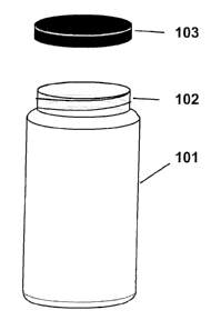
Fig. 1 depicts a typical container with lid for containing dry powered
measurable substances.
Fig. 2 depicts the two primary components of a basic spice-top according to
the prior art.
3
CA 02910472 2015-10-28
Fig. 3 depicts a different angle of the two primary components of a basic
spice-top according to the prior art.
Fig. 4 depicts the two primary assembled components of a basic spice-top
according to the prior art.
Fig. 5 depicts a different angle of the two primary assembled components of
a basic spice-top according to the prior art.
Fig. 6 depicts the additional components of a basic spice-top according to
the prior art.
Fig. 7 depicts the assembly of the components of a basic spice-top
according to the prior art.
Fig. 8 depicts the blade component of a spice-top according to a preferred
embodiment of the present invention.
Fig. 9 depicts a layer of the hub and ring of a spice-top according to a
preferred embodiment of the present invention.
Fig. 10 depicts the body of a spice-top showing the chamber divider walls
and spiral track according to a preferred embodiment of the present invention.
Fig. 11 depicts the body of a spice-top showing the outer wall spiral track
according to a preferred embodiment of the present invention.
Fig. 12 depicts the assembled spice-top according to a preferred
embodiment of the present invention.
Fig. 13 depicts the chambers ring according to a first variation of the
preferred embodiment of the present invention.
Fig. 14 depicts an alternate view of the chambers ring according to a first
variation of the preferred embodiment of the present invention.
Fig. 15 depicts the blade assembly, or chamber blocking device, according
to a first variation of the preferred embodiment of the present invention.
Fig. 16 depicts the blade assembly, or chamber blocking device, along with
the sliding turning key according to a first variation of the preferred
embodiment
of the present invention.
4
CA 02910472 2015-10-28
Fig. 17 depicts the assembled chambers ring and blade assembly according
to a first variation of the preferred embodiment of the present invention.
Fig. 18 depicts an x-ray view of the assembled chambers ring and blade
assembly according to a first variation of the preferred embodiment of the
present
invention.
Fig. 19 depicts a cross section showing the sealing mechanism between the
body component and the rotating cover component.
DESCRIPTION OF THE PREFERRED EMBODIMENT
The present invention is a device that is not only the top for a container of
spice or other food additive, but it is also a measuring device to measure and
then
dispense the spice or food additive contained. The advantage to having a
container top that can also measure and dispense the material contained is
that
one will never have to go find a separate measuring device (such as a
measuring
spoon), the measuring device will never have to be cleaned to enable it to be
used
to measure a second material having already been used to measure a first
material, and a user can gather all of the spices called for by a given recipe
and
also pre-measure each of them at the start of a given food preparation without
the need for bowls to hold the pre-measured amounts.
There are three things accomplished by the present invention. First, it is a
top for a container. Such a container might hold dry powdered food additives
such
as spices, sugars, salts, flavorings, and the like to be used by a chef.
Alternatively,
such a container could hold other substances such as chemicals for a chemist
or
medicines for a pharmacist.
CA 02910472 2015-10-28
Second, it is a measuring device. Food substances such as spices are
typically used in small measured amounts. Often these amounts are on the order
of a few teaspoons or a tablespoon and can include fractional amounts. A
tablespoon is the equivalent of three teaspoons and its volume is about 15,000
mm3 (a teaspoon is therefore about 5,000 mm3 and 1/8 teaspoon is about 625
mm3). As a measuring device, the top must be able to separate a specific
amount
of the material contained within the container from the rest of the material
still
within the container.
Third, it is a holding device of the measured amount of food substance.
Once measured, the specific measured amount of the material separated from the
rest of the material still within the container must be held until ready for
use.
While this third function is optional (the measured amount could be allowed to
spill
from the measuring means as it is being measured or as soon as it is
measured), it
is a convenience that can be included with the first two functions without
much
added complexity or cost.
Other features can include a means to return a measured amount to the
container in case of measurement errors or on-the-fly measurement changes or
for
refilling a container that is running low or is empty. Ideally, the device
should be
kept as small and compact as possible so that it is not top-heavy and so that
it
does not take up too much space. Additional features may enable the top to be
reusable and washable or the top can be for one-time use (for example, a snap-
on
top to enable a spice vendor to provide such a device with the packaging of
their
product knowing that it will be disposed of before any of the components might
wear out or break thereby enabling lower cost components to be used).
For the sake of simplicity, the present discussion will at times refer to the
present invention as a spice-top and to the measured material as dry powered
6
CA 02910472 2015-10-28
spice or, simply, spice; this is not to detract from the possibility of using
the
present invention in other implementations and with other substances. The
present discussion will first describe a basic spice-top to illustrate the
basic
mechanisms and provide a general understanding of the present invention. This
description is followed by a discussion of the limitations of that basic spice-
top. A
preferred embodiment of the present invention is thereafter described.
Figure 1 depicts a typical container for storing spices. This container is
typically a glass or plastic body 101 (i.e., a small jar) with a threaded top
neck
102 to which a metal or plastic lid 103 can be screwed thereon to secure and
contain the material therein. The opening of the container 101 can be thought
of
as being a plane defining a boundary between the interior of the container and
the
exterior of the container.
Devices having some of the basic features of the present invention are
depicted in Figures 2 through 6 and, as described in the Summary of the
Invention
paragraphs above, exist in the prior art.
Referring to Figure 2, a basic spice-top is depicted. The body of the spice-
top 201 has an outer shell 202 defining its maximum internal volume. This
outer
shell may be made of a clear material, such as plastic or glass, with
measurement
identifiers 203 formed thereon. This basic spice-top also has a floor 206 to
prevent the spice from entering (from below) the spice-top outside of the
volume
that is set for a given measure of spice. Floor 206 covers about half of the
bottom of body 201 while the other half of the bottom of body 201 has an
opening 207. This basic spice-top has an immovable inner wall 204 that is
attached to floor 206 and between the outer shell 202 and a central tube 205.
This immovable inner wall 204 acts as one of the surfaces to contain the
volume
of material to be measured.
7
CA 02910472 2015-10-28
A second component 210 is a movable insert that enables setting a volume
equal to the measure of spice. Movable insert 210 has a hollow shaft 211 that
is
inserted inside central tube 205 from below (gap 212 allows a space for the
wall
of tube 205). The floor 214 will come against the bottom of central tube 205
to
correctly position second component 210 within body 201 such that when second
component 210 is rotated within central tube 205, floor 214 will be in contact
with floor 206 as it slides below it. Movable insert 210 also has a wall 213
which
moves relative to immovable inner wall 204 and acts a second surface to
contain
the volume of material to be measured (when movable insert 210 is positioned
within body 201, wall 213 must be positioned within opening 207). The floor
214
of movable insert 210 also has indentations 215 therein; these indentations
are
part of a mechanism, described below, that enable the spice-top to click into
place
for each pre-set measure (the present example, for the sake of clarity and
simplicity in the present discussion, depicts only three measures - 1
teaspoon, 2
teaspoons and one tablespoon - but could include more or fewer click-positions
for more or fewer pre-set measures, respectively). Typically, movable insert
210
would be made of a brightly colored or other material that is easily visible
through
the outer shell 202 of body 201. As can be seen in Figure 3 (a slightly
different
angle of the view depicted in Figure 2), a small flexible arm 208 protrudes
out of
floor 206 and can engage one of the indentations 215 such that as movable
insert
210 is rotated within body 201, certain points of the rotation will snap into
place;
these snap-points correspond to pre-set volume measures of the device.
As depicted in Figure 4, a measurement is selected by rotating movable
insert within the body 201 such that immovable inner wall 204 and wall 213
form
a pie-shaped wedge (the measured volume 401 is also bounded by the portion of
outer shell 202 between the outer edges of immovable inner wall 204 and wall
213). The volume is determined by first calculating the area A of the
footprint of
8
CA 02910472 2015-10-28
the wedge. If the radius (to the inside surface) of the body 201 is rb and the
radius (to the outside surface) of central tube 205 is rt, then the area Afw
of the
footprint of the wedge can be found as:
Afw = Tr (r-b2 _ rt2 \ Eli/
/ 360
where e is the angle (in degrees) between immovable inner wall 204 and wall
213
and the volume of the measure Vm is equal to Afw multiplied by the height Hb
of
body 201. The volume of the measure is therefore:
Vm = TT Hb (rb? - rt2) 6)/360
To illustrate, if the radius (to the inside surface) of the body 201 is 15mm
and the
radius (to the outside surface) of central tube 205 is 2mm, then the area of
the
footprint when the immovable inner wall 204 and wall 213 are at an angle of 60
is
found as:
Afw = ii (1 52 _ 22) 60/360 = 115.7mm2
If it is desired that this 60 angle setting of immovable inner wall 204 to
wall 213
should correspond to a measure of 1 teaspoon (which is equal to a volume of
about 5000mm3), then the height of body 201 must be approximately 43.2mm:
Hb = 5000MM3/Af, = 50001=3/1 1 5.7MM2 43.2mm
A slightly different angle of the view of this assembly as depicted in Figure
4
is depicted in Figure 5 wherein the combination of floor 206 and floor 214 can
better be seen to cover all of the bottom of body 201 except for the bottom of
measured volume 401. It should also be apparent from Figure 5 why it is
suggested that body 201 should be made of clear material and why movable
insert should be made of a brightly colored material - the edge of wall 213
acts as
an indicator-line behind measurement identifier 203; in operation, a user of
the
9
CA 2910972 2017-03-16
device would turn movable insert 210 such that the edge of wall 213 clicks
into
place behind the measurement desired.
In addition to the above described components of this basic mechanism,
three additional components would be included (see Figure 6). The first
additional
component 601 is affixed to the top edge of hollow shaft 211 and wall 213 and
extends out to a grip-ring 602 that hangs down around the top edge of body
201.
This first additional component enables the user to grasp the grip-ring 602 in
order to rotate the movable insert 210 to the desired measure.
The second additional component is a half circle 610 that can be rotated to
cover the opening 207 of body 201 from below; this half circle is connected to
a
solid shaft 611 that runs through the center of hollow shaft 211. This second
additional component enables the user to rotate the half circle 610 by
grasping
and rotating the end of the solid shaft 611 so as to either cover or uncover
the
bottom opening 207 of volume 401. A snap-on (or screw on) cap 620, having a
hole 621 in its center to just large enough allow the solid shaft 611 to pass
through it, keeps the interior of the spice-top free of dust.
Figure 7 depicts the assembled basic device (with cap 620 removed). In
addition to this assembly, there will be a bottom ring that is attached to the
bottom of body 201 having an internal thread to match the threads found on the
neck 102 of various standard containers 101 such that the spice-top can
replace
the regular metal or plastic tops 103 of those various standard containers
101.
Alternatively, there could be a snap-on sleeve for permanently attaching the
top
to a container.
To operate the device, a user would (a) rotate the solid shaft 611 until the
half circle 610 uncovers the bottom of volume 401 exposed through opening 207
CA 2910972 2017-03-16
of body 201. The user would then (b) turn the grip-ring 602 to select the
desired
measure by clicking the edge of wall 213 into place behind the measurement
identifier 203 corresponding to that desired measure. (Note that steps a and b
could be reversed.) Next, the spice-top is (c) turned upside-down thereby
allowing
the spice in the container to spill into measured volume 401 (note that no
spice is
dispensed because the snap-on cap 620 is blocking the top of measured volume
401). Next, while the container is still upside-down, (d) the solid shaft 611
is
rotated until the half circle 610 covers the bottom opening of volume 401
exposed through opening 207 of body 201 (this will prevent thespice from
falling
back into the container when the container is returned to its upright
position).
Finally, (e) the container is returned to its upright position; when the
measured
amount of spice is needed, the snap-on cap is removed to dispense the measured
amount of spice that is contained within measured volume 401.
The basic mechanisms of the present invention should now be understood.
There is a chamber (measured volume 401) that is adjustable for different
sized
measures. There is an indicator to make a selected measured volume visible to
the
user (the edge of wall 213 behind the measurement identifiers 203). There is a
mechanism to prevent the user from accidentally selecting an in-between
measure
(the click mechanism of arm 208 along with indentations 215). There is a
mechanism to prevent spice from being dispensed until the user is ready for it
(the
snap-on cap) and there is a mechanism to capture the spice in the measuring
chamber and to prevent more spice from entering the measured volume while the
spice is being dispensed (the half circle). There are one or more mechanisms
to
enable the user to operate the device (the grip-ring to set the size of the
measure
and the end of the solid shaft to control the flow of spice between the
container
and the measuring chamber).
11
CA 02910472 2015-10-28
It will be obvious that in this basic version and as is an issue in the prior
art,
the user will have to become familiar with the operation of the device in
order to
use it correctly. It will also be obvious that in this basic version and as is
an issue
in the prior art, the device is excessively tall because a significant portion
of the
device (the volume above floor 206) is always empty.
The present invention in a preferred embodiment improves upon the
mechanisms of the basic version as outlined above while simplifying the
operation
of the device for the user. It also utilizes the entire volume of the device
for
measurement thereby cutting the height of the device in half. This makes the
device as small and compact as possible so that it is not top-heavy and so
that it
does not take up too much space and so that it is more likely to enable a
container fitted with the spice-top to fit into an existing or standard spice
rack. A
preferred embodiment of the present invention also replaces the continuously
adjustable measuring volume of the prior example with a incrementally
adjustable
measuring volume made up of multiple separate pre-measured chambers for
improved measurement accuracy.
We now discuss a preferred embodiment of the present invention, referring
initially to Figure 8. In the preferred embodiment, the functionality of
floors 206
and 214, half circle 610, wall 204, movable wall 213, and shaft 611 are all
comprised by a single blade component 800. Blade 801 is a spiraling blade
whose
leading edge 802 is 405 rotated from its trailing edge 803. Blade 801 is
attached
to a shaft 805. This spiral rotation of 405 comes from one full rotation (360
)
plus a partial rotation corresponding to the angular measure of one of a
plurality of
evenly sized, premeasured chambers.
Figure 9 depicts a portion of the spiral hub 901 that forms the central core
and a portion of the spiral ring 902 that forms the outer shell of the body of
the
12
CA 02910472 2015-10-28
present example of the preferred embodiment. Figure 10 depicts the full body
1001 of the present example of the preferred embodiment also showing the walls
1002 separating the individual stacked chambers 1003.
The outer edge 804 of blade 801 fits into and follows the outer track 904
in body 1 001 (made from layers of spiral rings 902); the shaft 805 of blade
801
fits within central hub 901 with the blade 801 passing through inner track
903.
Walls 1002 have openings 1004 between inner track 903 and outer track 904 to
allow blade 801 to pass through. As blade 801 passes through these chambers
and walls, it will block material from passing through the body of the device.
However, because the blade 801 spirals more than 360 (or more precisely,
because blade spirals the rotational distance of one additional chamber more
than
360 ), one chamber will be blocked both from above and below. This will ensure
that if the blade 801 is rotated such that its leading or trailing edge is
partway
across a given chamber opening, the material cannot pass around both edges and
through the body of the device. (More rotational distance in the length of the
blade will cover additional chambers and will still block the through path of
the
material however less rotational distance in the length of the blade by more
than
the thickness of the chamber dividing walls will enable material to seep
through
and should be avoided.)
In operation, when the leading edge 802 of blade 801 is roughly flush with
the bottom of body 1001, the device is considered sealed. As the blade is
rotated
(i.e., unscrewed), the blade 801 will move outward (i.e., away from the
container)
to expose the bottom openings of successive chambers to the container below. A
particular measure is selected by rotating the blade until the total volume of
chambers corresponding to the desired measure is exposed to the container
below, plus one additional chamber; this simultaneously unseals the container.
An
amount of material is dispensed by inverting the container thereby allowing
the
13
CA 02910472 2015-10-28
material to fill the volume of the chambers exposed when the measure was
selected, and then, while the container is still inverted, rotating the blade
back to
its original sealed position.
For example, to dispense a measure (from a device wherein a chamber is
1/8th of a rotation) corresponding to a single chamber's volume, the blade
would
initially be turned 900. When the material is to be dispensed, the container
with
the device thereupon is inverted - this will fill the bottommost two chambers.
While the container is still inverted, the blade is rotated back. As the blade
reaches
the 45 point, no material is dispensed because of the overlapping ends of the
blade, but as the blade continues to its original position, the contents of
all (i.e.,
one chamber) but the bottommost chamber is dispensed. To prevent a single unit
measure of material from remaining in this bottommost chamber, the wall of the
one chamber closest to the leading edge of the blade when the blade is in its
sealed position is absent.
In the present example of the preferred embodiment, the volume of the
device is divided into eight separate pre-measured chambers for improved
measurement accuracy, with each chamber having an angular measure of 1/8th of
a
full rotation, or 45 (360 + 45 = 405 ). If the chambers were not all the
same
size, the additional partial rotation of the blade 801 would have to
correspond to
the angular measure of the largest of the premeasured chambers.
The vertical distance between the ends of the blade 801 where they overlap
is determined similarly to the way in which the height of body 201 was
determined, above. As calculated above, if the radius (to the inside surface)
of
spiral ring 902 is 15mm and the radius (to the outside surface) of spiral hub
901
is 2mm, then the area of the footprint of each chamber when there are eight
14
CA 02910472 2015-10-28
chambers, resulting in the walls of each chamber being at a 450 angle
(ignoring the
thickness of the walls), is:
Afw = ( 1 52 _ 22) 45/360 = 86.8mm2
If it is desired that each of the chambers should hold a measure of 1/8
teaspoon
(which is equal to a volume of about 625mm3), then the height of each chamber
(i.e., the vertical distance between the portions of the blade 801 where the
leading edge 802 and trailing edge 803 overlap) must be approximately 7.2mm:
Hb = 625mm3/Af,, = 625mm3/86.8mm2 7.2mm
For a spice-top capable of measuring up to a tablespoon in increments of
1/8 teaspoon, at least three layers of spiral ring 902 will be necessary
(because
one tablespoon equals three teaspoons) and the spice top will have to be about
21.6mm tall. This would provide for 24 chambers of 1/8 teaspoon each in three
spiraling layers.
A preferred embodiment of the invention, will also include a cover portion
1101 (the exterior surface of which acts as the grip ring) to which the blade
shaft
805 is internally attached. As shown in Figure 11, an additional spiral track
1003
in fabricated on the exterior of body 1001. This spiral track 1003 mates with
a
spiral groove on the inner surface of cover portion 11 01 to better facilitate
the
raising and lowering of cover portion 1101 as it is rotated - this spiral
groove
matches the internal spiral of the blade such that the raising and lowering of
the
blade assembly 800 will match the raising and lowering of the cover portion
1101.
An indicator window 1104 is provided for viewing the desired measure (a
measurement indicator 1105 is printed, embossed, or otherwise attached to the
surface of the body 1001 corresponding to each chamber measurement position)
such that as the top portion is rotated and raised or lowered, the appropriate
CA 02910472 2015-10-28
measure will be displayed through the opening 1104. The lid will also comprise
an
opening 1102 to keep dust out of the device as well as a click stop mechanism
as
is well understood by those skilled in the art and as is described above for
the
basic spice top. The lid's surface is convex such that the material will tend
to flow
towards the opening when the device is inverted and such that the material can
be
better directed as it is being dispensed. Finally, a screw ring 1106 that
matches
the size and screw thread of the jar lid 103 of the spice container 101 on
which
the present invention is to be used such that the present invention can simply
be
screwed onto that jar as a jar lid replacement.
A variation on the preferred embodiment is depicted in Figure 13 through
Figure 18. In this variation, the device is smaller in the vertical direction,
but may
be more costly because it requires that more parts be assembled during
manufacture. In this variation, the cover portion (refer to 1101) rises and
lowers
on a threaded (refer to 1103) exterior of the device's body (refer to 1001) by
mating with a spiral groove on the inner surface of that cover portion (refer
to
1101) as it is rotated. But in this variation, the slope of these spiral
tracks is less
steep such that the cover portion rises and lowers to a lesser extent for each
revolution; this rising and lowering must only be sufficient to position the
measure
viewing window (refer to 1104) above any measure indicator (refer to 1105)
from
a prior or subsequent revolution such that only one measure indicator is
visible
through the measure viewing window at any time.
A first part in this variation, as depicted in Figure 13, is a chambers ring
1301. This part is similar to the body 1 001 of the preferred embodiment in
that it
has chambers 1305 formed by dividing walls 1304 that converge into a central
hub 1303 in which there is a center hole 1302. The angles of the walls 1304
are
determined in the same manner as they were for body 1001. The height of the
chambers ring 1301 is likewise determined in a similar way such that each of
the
16
CA 02910472 2015-10-28
chambers has a known volume (for example, 1/8 teaspoon). As depicted in Figure
14, this chambers ring 1301 can be inserted into the opening of the jar neck
102
of jar 101 (refer to Figure 1) and can be kept from rotating when the cover
portion is turned by having a key 1401 protruding from the inner wall of the
jar
neck 102 such that it mates with a slot 1306 in the outer wall of chambers
ring
1301.
Figure 15 depicts a blade unit that is a second part that is formed from
three components: a top plate 1503, a bottom plate 1507, and a hub 1501. This
part is a chamber covering device that could comprise three separate pieces,
it
could comprise two pieces (one piece consisting of one of the plates and the
other piece consisting of the combination of the other plate and hub formed as
a
single piece), or it could be formed as a single piece (in which case the
chambers
ring 1 301 would have to be formed as two halves or be split such that this
one
piece could be assembled with its hub 1 501 running through the center hole
1302
of chambers ring 1301, as will be described below. However this part is
created,
the top plate and the bottom plate will move together during operation. The
top
plate 1503 will have an opening 1504 bounded by edge 1505 and edge 1506.
The bottom plate 1507 will have an opening 1508 bounded by edge 1509 and
edge 1510. This blade unit performs the same function as the spiral blade 801
whereby the function of the first portion (or the leading portion 802) of the
spiral
blade is performed by the bottom plate and the function of the second portion
(or
the trailing portion 803) of the spiral blade is performed by the top plate.
The sizes and positions of opening 1504 and opening 1508 are as follows.
Opening 1504 of top plate 1503 is roughly the same size as one of the chambers
from the plurality of chambers 1305. Edges 1505 and 1506 of the opening in top
plate 1503 will generally align with the centerlines of the dividing walls
1304 on
either side of a given chamber. Opening 1508 of bottom plate 1507 is roughly
the
17
CA 02910472 2015-10-28
same size as three adjacent of the chambers from the plurality of chambers
1305.
Edges 1509 and 1510 of the opening in bottom plate 1507 will generally align
with the centerlines of the outer dividing walls 1304 of the two outer
chambers of
the three adjacent of the chambers from the plurality of chambers 1305. When
assembled as depicted in Figure 15 and aligned such that top plate 1503
completely covers all but one of the plurality of chambers 1305, the bottom
plate
1507 will cover the lower openings of three of the plurality of chambers 1305;
specifically, the one chamber having its upper opening uncovered by top plate
1503 will have its bottom opening covered by the center third of bottom plate
1507 (i.e., this one chamber as well as the single chamber on either side of
this
one chamber will have its lower opening covered by bottom plate 1507).
Hub 1 501 has an opening 1502 that runs the length (vertically, as
depicted) of hub 1 501 such that a matching shaped part 1 601 (e.g., a sliding
key
or keyed part) can pass through that opening 1502 in that hub 1501. Figure 16
depicts such a matching shaped part. Matching shaped part 1 601 fits the shape
of
opening 1502 such that this matching shaped part 1 601 can smoothly slide up
and down within opening 1502 when matching shaped part moves up and down.
But, when matching shaped part 1 601 is rotated about the vertical axis, the
assembly comprising top plate 1503, bottom plate 1507, and hub 1 501 will
likewise rotate about the vertical axis, as will be clear to those skilled in
the art.
The cross sectional shape of the keyed part can be almost any shape other than
circular, but a flat key as depicted or one shaped like a plus-sign (+) in
cross
section would work well, as will be clear to those skilled in the art.
Figure 17 (Figure 18 shows the same view in x-ray) depicts the assembled
combination of chambers ring 1301 and the assembly comprising top plate 1503,
bottom plate 1507, and hub 1501. As is shown, when the opening in top plate
1503 exposes one or two of the inner chambers, bottom plate 1507 will cover
the
18
CA 02910472 2015-10-28
bottom of those same chambers. In this way, powdered or granulated material
such as a spice (or medicine, or any of a multitude of other materials that
can
flow) will be unable to flow through the chamber and, instead will either flow
into
or out of the exposed chamber (depending on the orientation of the chamber on
a
container such as a spice bottle).
During use, the assembly of the chambers ring and the blade unit would be
positioned at the opening of a container (such as at the opening of neck 102
of a
spice jar 101). When the jar is standing upright, the spice will be in the jar
and any
spice that was remaining in the chambers of chamber ring 1301 will fall back
into
the jar as the cover and blade unit are rotated. When the jar is closed, the
outer
shell 1101 (as depicted in Figure 12) will be screwed to its fully lowered
position
on thread 1103. The top would then be turned in an opening motion (as any jar
top would be twisted for opening as is well understood by those skilled in the
art)
until the desired measurement amount indication 1105 is visible through the
window 1104. Click stops will help to provide tactile and/or audible feedback
to
the user and to provide stopping points when the top is rotated to each
measurement point. In Figure 12, the measure for 3/4 teaspoon is showing
through
the window. At this point, the blade unit will block three of the chambers
(these
chambers will be adjacent chambers) from the inside of the jar and will open
one
chamber (which will be the center chamber of the three adjacent chambers
blocked from the interior of the jar) to the top opening 1102. As the top 1101
(shown in Figures 11 and 12) is twisted and raised, the chamber covering blade
unit will likewise rotate, but will otherwise remain in its position within
the chamber
ring (it will not rise along with the top because matching shaped part 1601,
which
is fixed in the interior center of top 1101, will smoothly slide up and down
within
opening 1502 when matching shaped part 1 601 rises as the top rises). As such,
the spiral track 1003 on the exterior of body 1001 that mates with the spiral
groove on the inner surface of cover portion 1101 to facilitate the raising
and
19
CA 02910472 2015-10-28
lowering of cover portion 11 01 as it is rotated need (as shown in Figure 11)
only
be steep enough to allow indicator window 1104 to operate as the top portion
is
rotated and raised or lowered (i.e., such that the raising and lowering of
cover
portion 1101 will rise or lower just enough to only display the intended
measure
text through the opening 1104 and not the measure text of a vertically
adjacent
measure text).
Once the measured amount is selected by clicking the measurement 1105
into the viewing window 1104, the jar is inverted and spice will fill the five
chambers not blocked by blade 1507. While the jar is still inverted, the top
1101
is clicked back towards the closed position. As this is done, the blade 1507
will
move to cover the chamber adjacent to the three covered chambers and will
uncover the chamber to the opposite end of the opening in blade 1507.
Following
one eighth of a turn, three chambers will once again be covered (two of which
were covered when the jar was first inverted), however no spice will yet be
dispensed. As the top is twisted yet another eighth of a turn, and the first
of the
chambers that had become filled with spice when the jar was inverted will be
revealed by the opening in plate 1503 and the spice from that one chamber will
be
dispensed. With each additional eighth of a turn, one more chamber full of
spice
will be dispensed until the top 1101 is returned to its closed position.
Since the cover portion 11 01 rises and lowers as it is turned on threads
1103 that mesh with body 1001, the opening 1102 can be made to a plug an
opening that does rise or lower such that when the cover portion 11 01 reached
its lowest position, the plug meets with opening 1102 and seals the container.
In
this way, when the cover portion 11 01 is first turned to set the intended
measurement amount, cover portion 11 01 rises and separates from the plug to
unseal the container and as when the cover portion 1101 is later turned back
to
dispense the intended measurement amount (after the container is inverted),
CA 02910472 2015-10-28
cover portion 1101 lowers to meet the plug and seal the container. Figure 19
shows a general purpose version of this seal and unseal mechanism in cross
section that can be utilized with the variations of the present invention as
described herein.
In Figure 19, cover portion 1901 rises and lowers as it is turned on the
screw-thread-like track meshing with the body 1905 and as it does so, raises
and
lowers the center hub 1903. This center hub 1903 is surrounded by openings
1902 while fins attach this center hub to the outer walls of cover portion
1901.
The narrower portion 1904 extending out of the bottom of hub 1903 either acts
as the shaft 805 to which is attached the spiral blade (in the first
embodiment) or
acts as the matching shaped part 1 601 that is keyed to fit into and slide
through
the chamber ring or chamber cover assembly. When the cover portion is in its
fully
down position (as shown in the top drawing of Figure 19), the hub 1903 becomes
snug within the narrowing 1906 of the body 1905. However, as the cover portion
is rotated, it is raised away from its fully down position (as shown in the
lower
drawing of Figure 19), the hub 1903 pulls back from the narrowing 1906 of the
body 1905 allowing material to be dispensed to flow through the opening in the
center of narrowing 1906, around hub 1903 and out to the exterior of the
container and closure through openings 1902.
Many variations of this form of the invention will come to mind to those
skilled in the art. Figure 15 depicts a blade unit comprising three
components: a
top plate 1503, a bottom plate 1507, and a hub 1501. This blade unit could be
assembled from two or more pieces (such as a molded hub with stainless steel
plates 1503 and 1507) or it could be formed (for example by injection molding)
as a single plastic piece. The finished blade unit could be surrounded by the
chambers ring 1301 in which case the chambers ring 1301 would have to be
formed as two or more pieces that would be assembled about the center hub
21
CA 02910472 2015-10-28
=
1 501 of the blade unit. Alternatively, the chambers ring could have a single
opening such that this one piece could be snapped into place about the hub
1501
of the blade unit. The chamber ring could comprise more or fewer chambers than
the eight depicted in the figures and described above. The chambers ring could
be
molded into the interior of the screw ring body rather than be inserted into
the
opening of the jar neck as a separate piece. Screw ring 1106 could have clips
instead of threads such that the device would be snapped onto the top of a jar
rather than be screwed onto a jar. A separate lid (such as the lid 103 shown
in
Figure 1) can be included with the device that can screw-on or snap-on or
press-
on (i.e., held on by friction) to the top end of the cover portion to further
seal the
container; this lid could be left in place during dispensing in order to
capture the
measured amount of material within the top area of the closure until it is
needed.
Alternatively, the top plate 1503 and bottom plate 1507 could be fixed
relative to the interior of neck 102 of jar 101 and the chambers ring 1301
could
comprise the fixed opening 1502 and be able to rotate freely within the
interior of
neck 102. In this variation, as the top 1101 is twisted and raised, the
chamber
ring will rotate (instead of the top and bottom plates), but will otherwise
remain in
its position between top plate 1503 and bottom plate 1507 which are both fixed
to the interior of neck 102 (the chamber ring will not rise along with the top
because matching shaped part 1601, which is fixed in the interior center of
top
1101, will smoothly slide up and down within opening 1502 which is now a part
of
and in the center of the chambers ring 1301). The important thing is that the
chambers rotate relative to the top and bottom blades to enable spice to flow
in
and out of the selected chambers, regardless of whether it is the chambers
ring or
the blades assembly that turns along with the top. In this regard, the top
1101
could be attached with a groove as opposed to a screw-like thread such that as
top 1101 is twisted, it does not rise but does remain in place rotating about
in the
groove; while such an alternative is less desirable because it would leave to
the
22
CA 02910472 2015-10-28
user to count revolutions, it would nonetheless properly dispense measured
increments of the contents of the container.
Many other variations on the present invention may come to mind and the
present disclosure is not intended to limit the invention to the precise forms
disclosed herein. For example, the chambers need not all be identically sized.
For
example, there exists in the prior art, spice tops that include spice
grinders.
Grinders for grinding spices such as pepper or cinnamon have lacked adequate
means to measure how much of the spice has been ground and how much remains
to be ground. The present invention could incorporate such a grinder between
the
container and the top of the present invention. In this way, the measure first
would be set, the container then would be turned upside-down and the spice
would be ground until the measured volume in the spice top is filled thereby
causing the ground spice to back up into the grinder and prevent any more
spice
from being ground. The ground and measured spice will then be captured between
the grinder and the spice top such that the now ground spice can be dispensed
according to the teaching above when needed. Note that in an effort to keep
manufacturing costs low during mass production, several of the components
described herein could be molded as an integral part of body 1001 or of cover
portion 1101.
The foregoing description of an example of the preferred embodiment of the
invention and the variations thereon have been presented for the purposes of
illustration and description. It is not intended to be exhaustive or to limit
the
invention to the precise forms disclosed. Many modifications and variations
are
possible in light of the above teaching. It is intended that the scope of the
invention be limited not by this detailed description.
23