Note: Descriptions are shown in the official language in which they were submitted.
CA 02910608 2015-10-26
WO 2014/177912
PCT/IB2013/053426
CLASSIFIER
TECHNICAL FIELD
[01] The invention relates to a classifier. In particular, although not
exclusively, the invention relates to a reflux classifier for separation of
materials, such as ore particles, in mining and mineral processing.
BACKGROUND OF THE INVENTION
[02] The classification of particles according to their size and/or weight is
often used in mineral processing. In order to classify these particles it is
common to locate the particles in a solution to form a slurry. This slurry is
then passed through various types of equipment in order to separate the
particles into different sizes and/or densities.
[03] One of these types of equipment is a classifier that separates particles
according to their size and/or density. Reflux classifiers typically have a
slurry which is fluidized and passed through a plurality of parallel plates,
or
lamellae, which use gravity to separate solid particles from the liquid.
[04] While such reflux classifiers have been found to be relatively efficient
at separating, they are bulky and difficult to transport, primarily because of
the volume required around the parallel plates. This means that they are
expensive to install, often requiring specialized transportation equipment
adapted to carrying oversize loads. This not only limits their use in small
scale and temporary operations, but it may even mean that they cannot be
installed where desired due to infrastructure restrictions (e.g. over a bridge
or through a tunnel).
[05] It will be clearly understood that any reference herein to background
material or information, or to a prior publication, does not constitute an
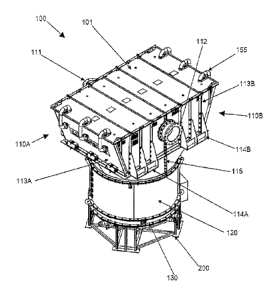
admission that any material, information or publication forms part of the
common general knowledge in the art, or is otherwise admissible prior art,
whether in Australia or in any other country.
CA 02910608 2015-10-26
WO 2014/177912
PCT/IB2013/053426
OBJECTS OF THE INVENTION
[06] It is an object of the invention to overcome or at least alleviate one or
more of the above problems and/or provide the consumer with a useful or
commercial choice.
[07] Other preferred objects of the present invention will become apparent
from the following description.
DISCLOSURE OF THE INVENTION
[08] In one form, although it need not be the only or indeed the broadest
form, the invention resides in a classifier comprising:
a mixing chamber for locating a slurry; and
a separation chamber in fluid communication with the mixing chamber
to separate solids from the slurry;
wherein at least the separation chamber is separable into a plurality of
parts.
[09] Preferably the classifier further comprises a fluidising chamber
connected to the mixing chamber. Preferably at least the mixing chamber
and separation chamber are separably mounted. Preferably the separation
chamber comprises at least one de-aeration chamber and/or at least one
launder.
[10] The separation chamber preferably comprises a series of plate arrays.
Preferably the plate arrays comprise a plurality of parallel plates.
Preferably
the plurality of parallel plates are inclined. Preferably the separation
chamber is separable into two parts, a first portion and a second portion,
typically for transportation. Preferably each of the first portion and the
second portion contain a series of plate arrays. Preferably each of the first
portion and the second portion contain at least one de-aeration chamber
and/or at least one launder.
[11] Preferably each of the first portion and the second portion comprise a
portion of a housing that encompasses the plate arrays. Preferably each
portion of the housing comprises at least an end wall and two side walls.
2
CA 02910608 2015-10-26
WO 2014/177912 PCT/IB2013/053426
Preferably the plate arrays of each portion is inclined in the same direction
with respect to the end walls such that when the two portions are mounted
together the arrays of each portion are inclined in opposed directions.
[12] Preferably the first portion and second portion have a mounting
system to affix the two portions together. Preferably the mounting system
comprises at least one flange on each of the first portion and second portion.
Preferably the at least one flange has a plurality of apertures and the first
portion and the second portion of the separation chamber are affixed
together by fasteners received in the apertures. Preferably the fasteners
include nuts and bolts.
[13] The separation chamber preferably has an outlet. The outlet
preferably has an overflow flange attached thereto. The outlet is preferably
located along a seam between the parts of the separation chamber. The
overflow flange preferably assists in affixing parts of the separation chamber
together for use.
[14] The outlet is preferably fluidly connected to a collector which is
preferably fluidly connected to launders. The launders are preferably fluidly
connected to an outlet side of the plate arrays and processed material
preferably traverses the plate arrays, launders, and collector before reaching
the outlet. Preferably a plurality of launders feed into a single collector.
Preferably the collector is located between two opposed sets of plate arrays.
Preferably the launders are arranged along opposed sides of the collector.
[15] The separation chamber preferably has an inlet. The inlet preferably
has an inlet flange attached thereto. The inlet is preferably located along a
seam between the parts of the separation chamber. The inlet flange
preferably assists in affixing parts of the separation chamber together for
use.
[16] The inlet is preferably fluidly connected to an inlet chamber. The inlet
chamber is preferably located between two opposed sets of plate arrays.
The inlet chamber preferably has a plurality of de-aeration chambers
connected thereto. Preferably the de-aeration chambers are arranged along
3
81792424
opposed sides of the inlet chamber. Preferably the inlet chamber is located
below the
collector and/or the inlet chamber and collector are preferably centrally
located
between the plate arrays. Preferably both the inlet chamber and collector are
formed
from the plurality of parts of the separation chamber.
[17] The slurry that is classified may be any mineralised slurry. Normally,
although
not exclusively, the slurry is a coal slurry.
[18] The classifier may include at least one hatch to enable access to the
inside.
The hatch is preferably located in the mixing chamber.
[19] In another form, the invention resides in a classifier comprising:
a mixing chamber for locating a slurry; and
a separation chamber in fluid communication with the mixing chamber to
separate solids from the slurry;
wherein the separation chamber has a collector located between two
opposed plate arrays.
[20] Preferably the classifier further comprises an inlet chamber.
Preferably the
inlet chamber is also located between the two opposed plate arrays. In a form
the
inlet chamber is located below the collector. Preferably at least one de-
aeration
chambers is located on either side of the inlet chamber. Preferably at least
one
launder is located on either side of the collector.
[20a] According to still another aspect of the present invention, there is
provided a
classifier comprising: a mixing chamber for locating a slurry; and a
separation
chamber in fluid communication with the mixing chamber to separate solids from
the
slurry; wherein the separation chamber has a collector located between two
opposed
plate arrays, and a plurality of launders feed into the collector.
[21] Further features of the present invention will become apparent from
the
following detailed description.
4
CA 2910608 2019-03-27
81792424
BRIEF DESCRIPTION OF THE DRAWINGS
[22] To assist in understanding the invention and to enable a person
skilled in the
art to put the invention into practical effect, preferred embodiments of the
invention
will be described by way of example only with reference to the accompanying
drawings, wherein:
[23] Figure 1 is a perspective view of a classifier according to an
embodiment of
the invention;
4a
CA 2910608 2019-03-27
CA 02910608 2015-10-26
WO 2014/177912 PCT/IB2013/053426
[24] Figure 2 is a perspective view of a classifier, with its cover removed,
according to another embodiment of the invention;
[25] Figure 3 is a side elevation view of the classifier illustrated in figure
2;
[26] Figure 4 is a front elevation view of the classifier illustrated in
figure 2;
[27] Figure 5 is a side elevation cross sectional view of the classifier
illustrated in figure 1;
[28] Figure 6 is a perspective cross sectional view of the classifier
illustrated in figure 1; and
[29] Figure 7 is another side elevation cross sectional view of the classifier
illustrated in figure 1.
DETAILED DESCRIPTION
[30] Figures 1 and 5 to 7 illustrate a first embodiment of the invention and
figures 2 to 4 illustrate a second embodiment of the invention. The two
embodiments are similar with the first embodiment illustrating a cover 101
and the second embodiment being generally larger than the first and having
no cover illustrated. Like numbering is used to describe common features
between the two embodiments and they will therefore be referred to
simultaneously.
[31] Figures 1 to 7 illustrate two embodiments of a classifier in the form of
a reflux classifier 100 used to separate material, such as coal particles, on
the basis of size and weight. The reflux classifier 100 has a separation
chamber in the form of a lamella chamber 110 located on top of a mixing
chamber 120 which is located above a fluidizing chamber 130. The reflux
classifier 100 is illustrated on a stand 200 which is typically removed after
installation.
[32] The lamella chamber 110 has an inlet 111 and an outlet 112 and is in
fluid communication with the mixing chamber 120 and the fluidizing
chamber 130. The lamella chamber 110 is formed of a plurality of separable
parts. In the illustrated embodiments of the reflux classifier 100 the lamella
chamber 110 is formed from two portions, namely a first part 110A having a
5
CA 02910608 2015-10-26
WO 2014/177912 PCT/IB2013/053426
first portion of a housing 113A and a second part 110B having a second
portion of a housing 113B. Together the two portions 110A and 110B form a
complete lamella chamber 110. Both the first and second portions of
housing 113A and 113B have supports 114A and 114B, respectively, that
can be used to mount the reflux classifier 100 to an external structure (not
shown).
[33] The first part 110A and second part 110B of the lamella chamber 110
each have a mounting system, in the form of corresponding flanges 115
(illustrated together in the figures), to affix the two portions together as
shown. The flanges 115 each have a plurality of apertures (not shown) that
receive fasteners in the form of nuts and bolts. The inlet 111 and outlet 112
are both located along the seam between the first part 110A and second
part 110B of the lamella chamber 110 and can be used to further affix first
part 110A and second part 110B of the lamella chamber 110 together for
use. If the first part 110A and second part 110B of the lamella chamber 110
are not to be separated again after installation, more permanent methods of
affixing may be utilized instead of, or as well as, flanges 115 with nuts and
bolts.
[34] The lamella chamber 110 has a series of plate arrays in the form of a
plurality of parallel plates 116 (see figure 2). The plurality of parallel
plates
116 are split between the first part 110A and second part 110B of the
lamella chamber 110 to form a first set of parallel plates 116A in the first
part 110A and a second set of parallel plates 116B in the second part 110B.
The parallel plates 116 are inclined relative to the axis of gravity to
provide a
classifying effect to material that passes through the plates 116. As can be
seen in figure 2 the first set of parallel plates 116A is inclined in an
opposite
direction to the second set of parallel plates 116B.
[35] A plurality of launders 117 are provided in each of the first part 110A
and second part 110B of the lamella chamber 110 to catch particles located
within the slurry after it has passed through the plurality of parallel plates
116. Each launder 117 has two substantially parallel side walls and an
6
CA 02910608 2015-10-26
WO 2014/177912 PCT/IB2013/053426
inclined base. The launders 117 are fluidly connected to a collector 118
which is located centrally between the first set of parallel plates 116A and
the second set of parallel plates 116B. The collector 118 is generally 'V'
shaped and receives material, such as coal slurry, once it has passed
through the launders 117. The collector 118 is fluidly connected to the
outlet 112 which enables processed material to exit the reflux classifier 100
from the collector 118.
[36] The mixing chamber 120 has a hatch 121 that allows access therein
for cleaning and maintenance, or the like. The fluidizing chamber 130,
which keeps slurry in a fluid state, has an underflow valve 131. The
underflow valve 131 is located adjacent the bottom of the fluidizing chamber
130 for removal of heavier particles and solids.
[37] The lamella chamber 110 is mounted to the mixing chamber 120 by
way of flanges with nuts and bolts. This allows the lamella chamber 110 to
be separated from the mixing chamber 120. The same applies between the
mixing chamber 120 and the fluidizing chamber 130 which allows the reflux
classifier 100 to be broken down into smaller pieces for transportation, or
the like.
[38] Figures 5 to 7 illustrate cross sectional views of the reflux classifier
100 where various internal components can be seen more clearly. The inlet
111 is fluidly connected to an inlet chamber 150 which has a plurality of de-
aeration chambers 151 connected thereto. The de-aeration chambers 151
each have a chute 152 that is fluidly connected to the mixing chamber 120
allowing slurry from the inlet chamber 150 to make its way to the mixing
chamber 120 for further processing after being de-aerated.
[39] A top of each de-aeration chamber 151 is inclined, defined by an
inclined base of respective launders 117 located directly above the de-
aeration chambers 151. An inclined de-aeration face 153, as seen in figure
7, urges lighter air particles upwards, toward an air outlet 154 at the top of
the de-aeration chamber 151. An air pipe 155 is connected to the air outlet
154 and is fluidly connected to the respective launders to allow air particles
7
CA 02910608 2015-10-26
WO 2014/177912
PCT/IB2013/053426
to bypass the mixing chamber 120 and lamella chamber 110. It should be
appreciated that the tops of the de-aeration chambers 151 need not be
formed from the inclined bases of the respective launders 40 and may be
formed irrespective of the launders 40. That is, the de-aeration faces 153
may be formed by other means.
[40] The mixing chamber 120 receives material to be processed, such as
coal slurry, from an open bottom of the de-aeration chambers 151. The
mixing chamber 120 can then deliver the material to the lamella chamber
110. Fluidizing chamber 130 ensures that material in the mixing chamber
120 remains in a fluid state for processing.
[41] In use, the reflux classifier 100 can be transported in separate parts
and put together on site relatively easily. Once installed, material to be
separated, such as coal slurry, is fed into the inlet 111 where it is
processed
by the reflux classifier 100. Specifically, the material to be processed is
passed from inlet 111 to inlet chamber 150 and then distributed to any one
of a plurality of de-aeration chambers 151. Any air in the material rises and
is urged toward air outlet 154 by inclined faces 153 of the de-aerators 151,
from where it is transferred to the launders 117 by air pipes 155.
[42] From the de-aeration chambers 151 the material then travels down
chutes 152 to the mixing chamber 120 located below the lamella chamber
110. The slurry is then fluidized by the fluidizing chamber 130 and then
passes upwardly through the parallel plates 116 of the lamella chamber 110
where particles located within the coal slurry are sorted according to size
and weight. Heavy and large particles pass into the bottom of the mixing
chamber 120 where they can be removed through underflow valve 131 into
a tundish (not shown) or similar. The lighter and smaller particles are able
to
pass through the plates 116 where they pass into the launders 117, into the
collector 118 and out of the outlet 112.
[43] Advantageously, the reflux classifier 100 can be separated into
manageable parts for transportation and then constructed on site. This can
provide more flexibility for transportation and can significantly reduce
8
CA 02910608 2015-10-26
WO 2014/177912 PCT/IB2013/053426
transportation costs. Furthermore, it may enable the reflux classifier 100 to
be used in situations where it could not otherwise be used due to size
restrictions on transportation. Similar improvements can be found in
decommissioning the reflux classifier 100 as it is more manageable to
disassemble and remove from site.
[44] The opposing arrangement of parallel plates 116A and 116B allows a
single collector 118 and outlet 112 to be used despite the two separate sets
of parallel plates 116A and 116B with associated launders 117. The
centrally located inlet chamber 150 and collector 118 allow for more de-
aeration chambers 151 and launders 117 to be provided than would
otherwise be possible without having multiple inlets and outlets and
increased complexity. Furthermore, the integrated de-aeration chambers
151 in the separable lamella chamber 110 allows for removal of air particles
from material to be processed, providing better separation of solids and
generally improving throughput and efficiency of the reflux classifier 100.
[45] In this specification, adjectives such as first and second, left and
right,
top and bottom, and the like may be used solely to distinguish one element
or action from another element or action without necessarily requiring or
implying any actual such relationship or order. Where the context permits,
reference to an integer or a component or step (or the like) is not to be
interpreted as being limited to only one of that integer, component, or step,
but rather could be one or more of that integer, component, or step etc.
[46] The above description of various embodiments of the present invention
is provided for purposes of description to one of ordinary skill in the
related
art. It is not intended to be exhaustive or to limit the invention to a single
disclosed embodiment. As mentioned above, numerous alternatives and
variations to the present invention will be apparent to those skilled in the
art
of the above teaching. Accordingly, while some alternative embodiments
have been discussed specifically, other embodiments will be apparent or
relatively easily developed by those of ordinary skill in the art. The
invention is intended to embrace all alternatives, modifications, and
9
CA 02910608 2015-10-26
WO 2014/177912
PCT/IB2013/053426
variations of the present invention that have been discussed herein, and
other embodiments that fall within the spirit and scope of the above
described invention.
[47] In the present specification and claims (if any), the word "comprising"
and its derivatives including "comprises" and "comprise" include each of the
stated integers but does not exclude the inclusion of one or more further
integers unless the context of use indicates otherwise.