Note: Descriptions are shown in the official language in which they were submitted.
CA 02910674 2015-12-09
54106-1923
1
Apparatus for Reducing a Magnetic Unidirectional Flux Component in the Core of
a
Transformer
BACKGROUND OF THE INVENTION
1. Field of the Invention
The invention relates to an apparatus for reducing a magnetic unidirectional
flux component
in the core of a transformer, i.e., a three-phase transformer, comprising a
plurality of
compensation windings that are magnetically coupled to the core of the
transformer when
used in transformers in the low voltage or medium voltage range and
transformers of very
high power (power transformers, high voltage direct current transmission
transformers).
2. Description of the Related Art
In electrical transformers, as used in energy distribution networks, the
situation may arise that
direct current is fed into the primary winding or secondary winding which is
undesirable.
Such a direct current feed as (the DC-component) may, for example, originate
from
conventional electronic structural components presently in use when
controlling electrical
drives or even in reactive power compensation. A further cause may be
geomagnetically
induced currents (GIC).
Due to solar winds, the earth's magnetic field is altered and thus very low
frequency voltages
are induced on conductor loops on the earth's surface. With long electrical
energy
transmission lines the induced voltage may cause relatively large low
frequency currents
(quasi direct currents). Geomagnetically induced currents occur approximately
in ten-year
cycles. They are evenly distributed on all (three) phases, may reach up to 30
A per phase and
may be discharged via the neutral point of a transformer. This leads to
considerable saturation
of the core of the transformer in a half-cycle and therefore to a high
excitation current in a
half-cycle. This additional excitation has a large harmonic component and as a
result, via the
stray field with the harmonic component, eddy current losses are produced in
the windings
and core components of the transformer. This may lead to local overheating in
the
transformer. Moreover, due to the high excitation requirement this leads to a
high
CA 02910674 2015-12-09
54106-1923
2
consumption of reactive power and a drop in voltage. Collectively, this may
lead to instability
of the energy transmission network. Put simply, the transformer behaves in a
half-wave in the
manner of a reactor.
Some energy transmission companies, therefore, already require in the
specification of
transformers 100 A direct current for the neutral point of the transformer.
As disclosed in WO 2012/041368 Al, use is made of an electrical voltage
induced in a
compensation winding and the electrical voltage is used for the compensation
of the
interfering magnetic unidirectional flux component by a thyristor switch being
connected in
series with a current limiting reactor, in order to introduce the compensation
current into the
compensation winding. This solution functions well for direct currents to be
compensated in
one range, where these direct currents are smaller by an order of magnitude
than
geomagnetically induced currents, i.e., approximately in the range below 10 A.
For
geomagnetically induced currents, the medium voltage level would have to be
used, i.e., in the
range of approximately 5 kV and high-powered thyristors used. Due to the high
power loss of
such thyristors this solution, however, is not economical.
A further solution for geomagnetically induced currents is represented by a
"DC blocker" in
which, in principle, a capacitor is connected to the neutral point of the
transformer. This
solution is problematic as a displacement voltage is produced by charging the
capacitor.
Moreover, the displacement voltage on the capacitor is limited so that it is
generally not
possible to block the entire direct current. A drawback with this solution is
also when it results
in a short circuit in the transmission network and therefore to zero currents.
Summary of the invention
In view of the foregoing, it is an object of the present invention to provide
an apparatus for
reducing a magnetic unidirectional flux component in the core of a
transformer, where the
apparatus, on the one hand, operates without the high power loss of powerful
thyristors and,
on the other hand, is not limited by a displacement voltage on a capacitor.
CA 02910674 2015-12-09
54106-1923
3
This and other objects and advantages are achieved in accordance with the
invention by an
apparatus in which a controllable current source is provided for feeding
current into the
compensation windings, where the controllable current source is arranged
electrically in series
with the compensation windings and specifically with the neutral point
thereof, which is
formed by the inputs of the compensation windings, a neutral earthing
transformer is provided
and is electrically conductively connected to the outputs of the compensation
windings, and
the current source electrically interconnects the neutral point of the
compensation windings
and the neutral point of the neutral earthing transformer.
The principle of the solution in accordance with the invention is once again
based on direct
current compensation via compensation windings, by current being fed
specifically into the
compensation windings, the effect thereof counteracting the unidirectional
flux component
and preventing the magnetizing of the core of the transformer. In other words,
"counter
ampere" turns are introduced into the transformer, where ampere turn is
another term for the
magnetic flux. In this case, the compensation current is introduced into the
compensation
windings by a controllable current source, where generally one compensation
winding is
provided for each phase of the transformer.
So that the compensation current may be introduced at low power, the problem
of the voltages
induced in the compensation windings has to be solved. This is implemented by
a neutral
earthing transformer, known per se, which is also denoted as a grounding
transformer or
earthing transformer. The neutral earthing transformer generates a neutral
point relative to the
phase-to-phase voltages of the compensation windings. As a result, the neutral
point of the
compensation windings and the neutral point formed by the neutral earthing
transformer are at
the same potential. Between these neutral points, a controllable current
source may be
therefore easily introduced. Moreover, the neutral earthing transformer has
the advantage in
that direct currents introduced via its neutral point and then uniformly
distributed over all
(three) of its arms, do not magnetize the core of the neutral earthing
transformer.
CA 02910674 2015-12-09
54106-1923
4
In an embodiment of the invention, at least one current limiting reactor is
electrically arranged
in series with the current source. By connecting a current limiting reactor
upstream, transient
voltages may be effectively filtered out, so that they do not pass through the
current source.
With the controllable current source, only the current that is required for
the compensation of
the undesired direct currents is supplied to the compensation windings. For
determining the
required compensation current, it may be provided that the controllable
current source is
connected to a measuring device for detecting the magnetic unidirectional flux
component in
the transformer. Such measuring devices are disclosed, for example, in WO
2012/041368 Al
in the form of a magnetic shunt component with a sensor coil. The shunt
component may be
arranged on the core of the transformer, such as, adjacent to an arm or the
yoke, in order to
conduct a portion of the magnetic flux in a bypass. From this magnetic flux
conducted in the
shunt, a sensor signal that has long-term stability may be very easily
obtained via a sensor
coil, where the signal after optional signal processing very clearly
represents the
unidirectional flux component (CD component).
The neutral earthing transformer may comprise windings in a zigzag arrangement
for
improved load distribution.
According to one aspect of the present invention, there is provided an
apparatus for reducing a
magnetic unidirectional flux component in the core of a transformer, in
particular a three-
phase transformer, comprising: a plurality of compensation windings which are
magnetically
coupled to a core of the transformer; a controllable current source for
feeding current into the
plurality of compensation windings, said controllable current source being
arranged
electrically in series with the controllable plurality of compensation
windings, and specifically
with a neutral point thereof, which is formed by the inputs of the
compensation windings; a
neutral earthing transformer electrically conductively connected to outputs of
the plurality of
compensation windings; and wherein the controllable current source
electrically interconnects
the neutral point of the compensation windings and the neutral point of the
neutral earthing
transformer.
CA 02910674 2015-12-09
54106-1923
Other objects and features of the present invention will become apparent from
the following
detailed description considered in conjunction with the accompanying drawings.
It is to be
understood, however, that the drawings are designed solely for purposes of
illustration and not
as a definition of the limits of the invention, for which reference should be
made to the
5 appended claims. It should be further understood that the drawings are
not necessarily drawn
to scale and that, unless otherwise indicated, they are merely intended to
conceptually
illustrate the structures and procedures described herein.
Brief Description of the Drawings
For the further description of the invention reference is made in the
following part of the
description to the figures, further advantageous embodiments, details and
developments of the
invention being able to be derived therefrom, in which:
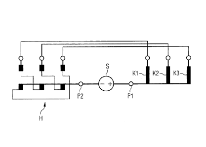
Figure 1 shows a circuit in accordance with the prior art for
introducing compensation
current into a compensation winding comprising a thyristor circuit and
Figure 2 shows a circuit in accordance with the invention for
introducing compensation
current into compensation windings via a controllable current source.
Detailed Description of the Exemplary Embodiments
With reference to the prior art in Fig. 1, in direct current compensation,
direct current is
introduced in a targeted manner into a compensation winding K to eliminate the
direct current
magnetizing of the transformer core. For introducing the required magnetic
flux (i.e., direct
current ampere turns) into the compensation winding K, use is made of the
alternating voltage
induced in the compensation winding K, and the compensation winding K
functions as an
alternating voltage source. On the compensation winding K, a switching unit T
configured as
a thyristor is connected in series with a current limiting reactor L. The
required direct current
may be adjusted by voltage-synchronous ignition at a specific ignition time of
the thyristor T.
If the thyristor is ignited in the voltage zero transition, the maximum direct
current is set
which, however, is superimposed by an alternating current having the amplitude
of the direct
current and the network frequency. If the thyristor T is ignited later, the
direct current is
CA 02910674 2015-12-09
54106-1923
6
smaller but harmonic alternating currents are also produced. The current path
in the thyristor
T is limited by a current limiting reactor L, and the permitted thermal load
of the thyristor T is
dimensioned for the current limit.
With reference to Fig. 2, a controllable current source S and a neutral
earthing transformer H
are used instead of the thyristor T, and in this disclosed embodiment in
accordance with the
invention also instead of the current limiting reactor L.
The controllable current source S is electrically directly connected in series
with the
compensation windings K1 , K2, K3 and namely the inputs of the compensation
windings K 1,
K2, K3 are connected together at a neutral point P1 that is directly connected
to the current
source S. One respective compensation winding K 1 , K2, K3 is arranged on an
arm of a three-
phase transformer (not shown).
In the neutral earthing transformer H, the three (the upper in this case)
primary windings are
each connected at their one terminal end to an output of a compensation
winding K 1, K2, K3.
The other terminal ends are each connected at a terminal end of the three (the
lower in this
case) secondary windings in a zigzag arrangement. The other terminal ends of
the secondary
winding are brought together in an artificial neutral point P2 which is
directly connected to the
controllable current source S.
A zigzag arrangement means that the primary and secondary windings of a phase
(in this case
a compensation winding) are arranged on different arms of the neutral earthing
transformer H
and/or that the windings on the same arm belong to different phases (different
compensation
windings).
Primary and secondary windings of the neutral earthing transformer H are of
the same size
and, therefore, have approximately the same winding number but the current
passes through
them in different directions. Thus, with the same current in different
windings, no flux is
induced in the core of the neutral earthing transformer H.
CA 02910674 2015-12-09
54106-1923
7
The current source S is electrically connected, on the one hand, directly to
the neutral point P1
of the compensation windings K1 , K2, K3 and, on the other hand, to the
neutral point P2 of
the neutral earthing transformer H.
Similarly to Fig. 1, in Fig. 2 a current limiting reactor L could also be
arranged electrically in
series with the current source S.
By the method of the invention, large compensation currents and thus large
demagnetizing
turns may be introduced into the transformer at low power. The components at
the medium
voltage level that are used, such as the neutral earthing transformer H, are
known per se and
available. In turn, introduction of compensation windings with induced
voltages at the
medium voltage level represents proven technology. The advantage of the
present invention is
that the controllable current source is at earth potential. It is possible to
reach 10 kV, 20 kV or
30 kV at the medium voltage level. At the same time, compensation direct
current is reduced,
and it is possible to use commercially available current sources. The neutral
earthing
transformer is very insensitive to direct currents at the neutral point as
these are uniformly
distributed and do not cause any additional magnetizing of the core.
Thus, while there have been shown, described and pointed out fundamental novel
features of
the invention as applied to a preferred embodiment thereof, it will be
understood that various
omissions and substitutions and changes in the form and details of the devices
illustrated, and
in their operation, may be made by those skilled in the art without departing
from the spirit of
the invention. For example, it is expressly intended that all combinations of
those elements
which perform substantially the same function in substantially the same way to
achieve the
same results are within the scope of the invention. Moreover, it should be
recognized that
structures and/or elements shown and/or described in connection with any
disclosed form or
embodiment of the invention may be incorporated in any other disclosed or
described or
suggested form or embodiment as a general matter of design choice. It is the
intention,
therefore, to be limited only as indicated by the scope of the claims appended
hereto.