Note: Descriptions are shown in the official language in which they were submitted.
CA 02910731 2015-10-28
WO 2014/178063
PCT/IN2014/000190
A PROCESS FOR FABRICATION OF YTTERBIUM DOPED OPTICAL FIBER
FIELD OF THE INVENTION
The present invention relates to a process for fabrication of ytterbium (Yb)
doped
optical fiber through vapor phase doping technique. More particularly, the
invention
relates to fabrication of Yb/A1 doped optical fiber by vapor phase deposition
technique.
BACKGROUND OF THE INVENTION
Rare earth (RE) doped optical fibers has found promising applications in the
field of
optical amplifiers, fiber lasers and sensors. The RE elements doped into the
core of such
fibers act as the active medium. Different REs like Er, Nd, Yb, Sm, Ho and Tm
can be
doped to get lasing and amplification covering a wide range of wavelengths. RE
doped
fiber lasers are replacing gas based or solid state lasers in most of the
applications due
to their compactness, excellent beam quality and easy handling capability. As
a result,
there has been around 16% market growth of fiber laser with the overall sales
touched
$1.35 billion for the year 2012 as reported by Industrial Laser Solutions.
Fiber laser
devices are suitable for a variety of applications viz, material processing
(cutting,
grinding and engraving), range finding, medical and military applications.
Thus
fabrication of RE doped fibers with varied designs, compositions and
appropriate RE
concentration attracts a lot of research interest. The improvement in the
properties of the
fibers and increase in the process reproducibility remain the prime objective.
Reference may be made to US Patent No. 4,826,288 (1989) by R. J. Mansfield, B.
C.
McCollum, R. P. Tumminelli, "Method for fabricating optical fibers having
cores with
high rare earth content" wherein, the Modified chemical vapor deposition
(MCVD)
process with vapor phase chelate delivery technique is adopted for
incorporation of high
RE ions at the core of the fiber. The core layer deposition was done with
silica along
with refractive index raising dopant like A1203 and RE oxides like Nd203 or
Yb203 and
1
CA 02910731 2015-10-28
WO 2014/178063
PCT/IN2014/000190
Er203. Al2C16 and RE(thd)3 served as Al and RE incorporating agent
respectively.
Helium used as carrier gas of Al and RE compounds. The sources of RE vapor
made of
glass columns which were filled with solid RE-chelates along with an inert
compound
such as granulated high purity SiO2 or A1203. The columns were heated upto a
maximum temperature of 200 C. The temperature of transport line for Nd(thd)3
was in
the range of 210 C ¨ 225 C. Various gaseous components were delivered to the
reaction
zone approximately 250 C, at most. The preferred concentrations of materials
in the
glass core were: 2 ¨ 20 wt% of A1203, 0.1 ¨ 4 wt% of Nd203 and remainder being
SiO2
glass. Another fiber also made with combination of Yb3+ and Er3+ ions. Total
RE203
concentration was in excess of 5 wt%.
Drawbacks: - They believe to have RE content in the core of preform of about
0.1 to 10
wt% or more. But in claim part, they only claim about 0.5 wt% of RE203.
Nothing is
said about the length of the preform and distribution of the dopants in the
longitudinal
as well as the radial direction.
Reference may be made to US Patent No. 5,961,682 (1999) by Yong-woo Lee, A. N.
Guryanov, V. F. Khopin, D. D. Gusovsky, "Method of fabricating optical fiber
doped
with rare earth element using volatile complex" wherein, reaction of volatile
RE-chelate
compounds with SiC14 and 02 took place. The surface of the tube was heated and
water
cooled to deposit porous core layer on which Al2C16 or SiF4 vapors absorbed.
Volatile
organic metal ligand composed of tris-cyclopentadienyl or tris-
isopropylcyclopentadienyl compound of metal ions Er, Dy or Yb used for RE
incorporation. Organic ligand bubbler temperature varied in the range of 150 ¨
300 C
while Al2C16 bubbler temperature was in the range of 140 ¨ 150 C. Freon gas
was used
to reduce OH content in the fiber. The difference in the refractive index
between
cladding layer and core layer greater than 0.025 achieved.
Reference may be made to US Patent No. US 6,474,106 B1 (2002), by C. E.
Crossland,
Gang Qi, "Rare earth and Alumina-doped optical fiber preform process" wherein,
an
OVD process has employed to deposit porous soot core layer of Si02 ¨ Ge02 ¨
A1203 ¨
2
CA 02910731 2015-10-28
WO 2014/178063
PCT/IN2014/000190
Er203 and then cladding layer employed on it as soot¨ on ¨soot process and
then
consolidation of the soot was done following soot¨ on ¨glass process in which
the
mandrel moved leaving a hollow, cylindrical soot blank core. The soot blank
core was
then consolidated and sintered in certain steps, to form a core rod known as
cane. The
temperature of solid AlC13 containing sublimator was varied preferably in
between
150 C ¨ 170 C with Helium/Argon flow rates of about 0.5 to 0.7 slm to
incorporate
various concentration of A1203 in the final preform. Er containing precursors,
such as
Er(F0D)3 or Er(C30I-130F2106)3, were heated in a bubbler to a temperature
range of
130 C ¨ 200 C. Higher Al containing preforms were reported as inclusions free.
Er203
concentration was around 500 ppm in each preform but concentrations of Ge02
and
A1203 were varied in between 10 to 20 wt% and 2 to 10 wt% respectively.
Reference may be made to US Patent No. US 2005/0276555 Al (2005) by T. Haruna,
S. Ishikawa, T. Tam, T. Katayama, N. Taira, "Glass-body-producing method and
optical glass body and optical fiber" wherein, an organometallic compound is
heated
from the outside into a glass pipe so that it decomposed into an organic
constituent and
metallic constituents upstream of the reaction zone. The organic part
condensed and
deposited there and the metallic part oxidized and deposited with glass layer.
The
decomposition performed by thermal -decomposition or photo-decomposition by
using
heat source or light source at temperature 100 C ¨1000 C. During consolidation
step
C12 gas was used for dehydration purpose to reduce the OH content. The OH
content in
the glass body had been reduced to 10 ppm, even at most 1 ppm.
Reference may be made to R. P. Tutnminelli, B. C. McCollum, E. Snitzer,
Journal of
light wave Technology, Vol. 8, No. 11, (1990) pp. 1680-1683, "Fabrication of
high
concentration rare earth doped optical fibers using chelates" wherein, an
individual
AlC13 delivery line and three separate sources of RE-chelates were used. The
RE-
chelate columns were heated individually to the temperature in between 150 to
210 C.
Carrier gas Helium was preheated and passed through RE and Al columns and
delivered
to a rotating mechanical seal via a heated delivery system. RE, Al and other
reactants
3
PCT/IN 2014/000 190 ¨ 05-02-2015
LLS 288 REPLACEMENT SHEET PCT/IN2014/000190
kept separated to prevent prereaction in the heated delivery tube. A ribbon
burner was provided
throughout the entire length prior to the reaction zone. The fiber containing
11 wt% Yb203 and
0.2 wt% Er203 had been prepared. Another fiber containing 1.0 wt% of Nd203 had
base losses
<10 dB/km at 1130 nm. For high concentration fiber base loss was around 150
dB/km at 1064
nm at 80 C with OH concentration in between 15 to 20 ppm.
Drawbacks: - Nothing is said about the length of the preform and the
distribution of the dopants
in the longitudinal as well as the radial direction. For high concentration
fibers, background loss
and OH concentration is much higher.
Reference may be made to S. D. Jackson, T. Ryan, S. Mossman, Optics
Communications, Vol.
216, (2003) pp. 401-404, "High power Tm+3-doped silica fibre laser fabricated
using chelate
delivery deposition" wherein, a single dopant chamber contained a mixture of
Tin3+ and Al
chelate which was heated to 200 C and the vapor is entrained in the flow of
02, helium and
other precursor materials. Then oxidation and deposition as porous layer took
place which dried
using C12 gas. The layer then sintered and collapsed in usual manner. The
double-clad fiber had
a ¨12 gm core diameter with NA of 0.19. Tm3 concentration was of ¨0.35 wt%
and
background loss of <10 dB/km at 1300 nm.
Drawbacks:- Concentration level is significantly lower than that already
achieved by solution
doping method. The chelate heating system was not optimized and the process
was limited to be
batch type, using only 0.3 gm of chemical. They expect lower background losses
but value is
not mentioned.
Reference may be made to US 2002/0088252, wherein, a method and apparatus for
the
manufacture of an optical fiber preform having incorporated therein a rare
earth halogen is
disclosed.
Drawbacks:- Due to the incorporation of RE-chloride, boat temperature and
multi-concentric
delivery line temperature has to be maintained >900 C. Moreover, when RE-
chloride passes
through the innermost part of the concentric tube it encounters higher
temperature which may
result in decomposition of precursor material.
Reference may be made to E. H. Sekiya, P. Barua, K. Saito, A. J. Ikushima,
Journal of Non-
Crystalline solids, Vol. 354, (2008) pp. 4737-4742 , "Fabrication of Yb-doped
silica glass
through the modification of MCVD process" wherein, Yb(DPM)3 furnace
temperature was
varied in the range of 200 ¨ 250 C, but AlC13 furnace temperature was kept
fixed at 130 C.
Temperature of the delivery lines including that of SiC14 and other gaseous
components were
A
AMENDED SHEET
CA 2910731 2015-10-29
PCT/IN 2014/000 190 - 05-02-2015
LLS 288 REPLACEMENT SHEET PCT/IN2014/000190
kept higher than the temperature of the Yb furnace to avoid condensation of
precursor material
in the nozzle part. Deposition conditions such as deposition temperature,
SiC14 flow and burner
speed was fixed to 1950 C, 0.6 g/min and 145 mm/min respectively. Yb3+
concentration
obtained for only Yb-doped runs was in the range of 0.15 ¨ 1.2 wt% while Yb 3+
concentration
for Yb and Al doped runs was maximum of 0.7 wt% with A13+ concentration around
0.4 wt%.
The variation in refractive index was of 5% in the longitudinal direction and
10% in the
radial direction.
Drawbacks: - Soot layer deposition took place over a length of 550 mm of
silica tube. But
uniform core diameter and dopant distribution obtained in a preform of length
of only 300 mm.
Y131 concentration is much lower compared to conventional method. SiC14 and
other gases
delivered from normal MCVD gas cabinet also have to send at higher temperature
than Yb
furnace, otherwise dopants will get condensed in the concentric nozzle part.
Variation in dopant
distribution in radial direction is around 10%.
Reference may be made to US 2003/0217569, wherein, a preform for a low fiber
optic cable
and method and apparatus for fabricating the preform is disclosed. The method
includes
providing AlC13 and CVD precursors locally doping CaC13.
Drawbacks:- Discloses a completely different glass system. The emphasis is on
addition of CaO
for lowering sintering temperature. Further, RE =vapor delivery process is
through multi
concentric tubes.
Reference may be made to B. Lenardic, M. Kveder, Optical society of America,
' OSA/OFC/NFOEC 2009, "Advanced vapor-phase doping method using chelate
precursor for
fabrication of rare earth-doped fibers" wherein, the precursor vapors
volatized at temperatures
between 100 C ¨ 220 C and transported to the reaction zone by a system of
heated conduits,
specially constructed high-temperature rotary seal and sliding precursor vapor
injection tube.
Instead of burner MCVD is equipped with an induction furnace. Two different
designs of
sublimator used, bulk sublimator and flat bed sublimator. Flow rate of 02
through SiC14 bubbler
was set to 100 to 250 sccm at bubbler temperature of 35 C with carriage
traversed speed of 100
mm/min. Collapsing was comparatively faster as higher amount of heat supplied
by induction
furnace. Relationship evaluated between evaporation rate of Yb-chelate and
final Yb203
concentration in the fiber and evaporation rate of AlC13 with A1C13 sublimator
temperature. One preform with Er3+ concentration of 2680 ppm and Al3+
concentration
AMENDED SHEET
CA 2910731 2015-10-29
CA 02910731 2015-10-28
WO 2014/178063
PCT/IN2014/000190
of 4900 ppm and another preform with Yb3+ concentration of 31300 ppm and Al3+
concentration of 12000 ppm have been fabricated.
Drawbacks: - Soot layer deposition took place over a length of 600 mm of
silica tube.
But final preform of length obtained of about 250 - 350 mm. Larger diameter of
substrate tube (30/27 or 25/22) was compulsory to permit sliding injection
tube into the
substrate tube. Only 20 core layer can be deposited. From the refractive index
profiles
of the preforms, it is clear that the preforms having high center dip and
variation in
dopant concentration in radial direction.
Reference may be made to J. Sahu et. al., Optical society of America,
OSA/CLEO/QELS 2010, "Rare-earth doped optical fiber fabrication using novel
gas
phase deposition technique" wherein, the chelate compound was heated in a
crucible
directly within the MCVD structure which is placed in a non-rotating tube
close to the
deposition zone. The crucible can be heated upto 800 C and allowing inert gas
to flow
down the non-rotating tube and carry the generated vapors to the reaction zone
while
SiC14 and other dopants are added to the rotating part of the outer tube. High
level of Al
incorporated to give NA of 0.24 with base loss ¨ 3dB/km. Yb3+ concentration of
9000 -
20000 ppm-wt was achieved by adjusting crucible temperature_ with the base
loss in the
range of 30 ¨ 70 dB/km. Core diameter of the fabricated fiber was 20 ptm
(overall fiber
diameter 125 um).
Drawbacks: - As Helium passes through the crucible, it will carry the vapors
generated
at the upper surface of the crucible. So evaporation rate of RE-chelate
compound will
be dependent of exposed surface area. It will be problematic to incorporate
two or more
RE compounds simultaneously.
Reference may be made to US Patent No. 5474588 (1995) by D. Tanaka, A. Wada,
T.
Sakai, T. Nozawa and R. Yamauchi, "Solution doping of a silica with erbium,
aluminium and phosphorus to form an optical fiber" wherein a manufacturing
method
for Er doped silica is described in which silica glass soot is deposited using
VAD
apparatus to form a porous soot preform, dipping the said preform into an
ethanol
6
CA 02910731 2015-10-28
WO 2014/178063
PCT/IN2014/000190
solution containing an erbium compound, an Al compound and a phosphoric ester,
and
desiccating said preform to form Er, Al and P containing soot preform. The
desiccation
is carried out for a period of 24 -240 hours at a temperature of 60 to 70 C in
an
atmosphere of nitrogen gas or inert gas. This desiccated soot preform is
heated and
dehydrated for a period of 2.5 - 3.5 hours at a temperature of 950 to 1050 C
in an
atmosphere of helium gas containing 0.25 to 0.35% chlorine gas and further
heated for a
period of 3-5 hours at a temperature of 1400 to 1600 C to render it
transparent, thereby
forming an erbium doped glass preform. The segregation of AlC13 in the preform
formation process is suppressed due to the presence of phosphorus and as a
result the
.. doping concentration of A13+ can be set to a high level ( >3 wt% ). It has
been also
claimed that the dopants concentration and component ratio of Er, Al and P
ions having
extremely accurate and homogeneous in the radial as well as in longitudinal
directions.
Reference may be made to U.S. Patent No. 6,751,990 (2004), by T.
Bandyopadhyay, R.
Sen, S. K. Bhadra, K. Dasgupta and M. Ch. Paul, "Process for making rare earth
doped
optical fiber" wherein, unsintered particulate layer containing Ge02 and P205
core layer
is deposited and doping by soaking the porous soot layer into an
alcoholic/aqueous
solution of RE-salts containing co-dopants like A1C13/Al(NO3)3 in definite
proportion is
carried out. The porosity of the soot, dipping period, strength of the
solution and the
proportion of the codopants are controlled to achieve the desired RE3+
concentration in
the core and to minimize the core clad boundary defects. In subsequent steps
drying,
oxidation, dehydration and sintering of the RE containing porous deposit are
performed
followed by collapsing at a high temperature to produce the preform. The RE3+
distribution in the resulting fiber matches with the Gaussian distribution of
the pump
beam to increase the overlapping and pump conversion efficiency.
7
CA 02910731 2015-10-28
WO 2014/178063
PCT/IN2014/000190
The drawbacks of the above mentioned processes are as follows:
I. Low concentration of dopant material as compared to conventional
process;
2. Decomposition and condensation of RE precursor materials occurred prior to
reaction zone;
3. Variation of dopant concentration along the longitudinal and radial
direction of the
preform;
4. Shorter preform length due to loss in effective deposition zone;
5. Process parameters are not optimized.
OBJECTS OF THE INVENTION
The main object of the present invention is to provide a process of
fabrication of Yb
doped optical fiber through vapor phase doping technique which obviates the
drawbacks of the hitherto known prior art as detailed above.
Still another object of the present invention is to fabricate large core Yb203
doped
preform/fiber difficult to fabricate employing conventional solution doping
process.
Another object of the present invention is to dope Yb203 and A1203
simultaneously with
silica during formation of core layer for good homogeneity.
Yet another object of the present invention is to fabricate preform/fiber
comprising of
high concentration Yb203 and A1203.
Another object is to increase effective preform length suitable for drawing
long length
of fiber.
Still another object of the present invention is to provide a method where the
Yb203
concentration uniformity along the longitudinal and radial direction of the
preform/fiber
core is superior to the hitherto known methods.
8
CA 02910731 2015-10-28
WO 2014/178063
PCT/IN2014/000190
Yet another object of the present invention is to provide a method where the
core-clad
interface problem associated with high A1203 doping level is eliminated.
Still another object of the present invention is to provide a reliable process
of making
large core Yb doped preform/fiber.
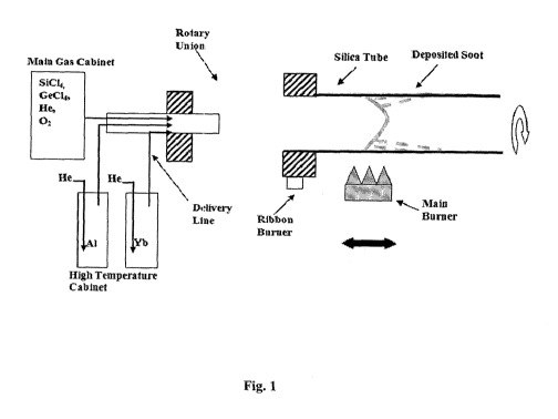
BRIEF DESCRIPTION OF ACCOMPANYING DRAWINGS
Fig. 1 represents OFC-12 MCVD system with high temperature vapor delivery
unit.
Fig. 2 represents flowchart for fabrication of Yb doped optical fiber by the
present
invention.
SUMMARY OF THE INVENTION
Accordingly, present invention provides a process for fabrication of ytterbium
(Yb)
doped optical fiber through vapor phase doping technique, said process
comprising the
steps of:
(i) depositing pure silica cladding layers inside a silica glass substrate
tube at a
temperature in the range of 1900 to 1980 C using Modified chemical vapor
deposition (MCVD) process;
(ii) sublimating Aluminum(A1) salt and Yb-chelate in their respective
sublimator
chamber at a temperature in the range of 100 to 170 C and 180 to 260 C
respectively to obtain Al-precursors and Yb-precursors;
(iii) introducing preheated inert carrier gas in the sublimator chamber of
step (ii)
at a flow rate in the range of 10 to 50 seem for Al precursors and 100 to 300
seem for Yb precursors;
(iv) transporting Al and Yb precursors with inert gas obtained in step
(iii) to the
substrate tube with the adjustment of temperature of ribbon burner in the
range of 180¨ 370 C;
9
CA 02910731 2015-10-28
WO 2014/178063
PCT/IN2014/000190
(v) passing 02 gas into a SiC14 bubbler at a temperature in the range of 15
to
40 C and a flow rate in the range of 80 to 150 sccm to transport SiC14-02 gas
mixture to the substrate tube;
(vi) mixing SiC14, 02, Al precursors, Yb-precursors, and inert gas in the
substrate
tube followed by concurrent oxidation to form Si02, A1203 and Yb203;
(vii) depositing a sintered core layer comprising SiO2-A1203-Yb203 with
targeted
A1203 and Yb203 concentrations to obtain a deposited tube;
(viii) collapsing the deposited tube at a temperature in the range of 1900
to
2300 C to obtain fabricated preform; and
(ix) drawing fibers from the fabricated preform obtained in step (viii) to
obtain
ytterbium (Yb) doped optical fiber.
In an embodiment of the present invention, 4-10 pure silica cladding layers
are
deposited in the substrate tube.
.. In yet another embodiment of the present invention, the temperature is in
the range of
1910-1960 C.
In another embodiment of the present invention, the Al salt is A1C13.
In yet another embodiment of the present invention, the sublimating
temperature for Al
salt is in the range of 120 to 160 C.
In yet another embodiment of the present invention, the Yb-chelate is
Yb(thd)3,
In yet another embodiment of the present invention, the sublimating
temperature for
Yb-chelate is in the range of 200 to 240 C.
In yet another embodiment of the present invention, the inert carrier gas is
helium.
In yet another embodiment of the present invention, the temperature of ribbon
burner is
in the range of 200- 350 C.
CA 02910731 2015-10-28
WO 2014/178063
PCT/IN2014/000190
In yet another embodiment of the present invention, the number of core layers
is in the
range of 1 to 40.
In yet another embodiment of the present invention, the temperature of
deposition of
sintered core layer is in the range of 1770 to 1920 C.
In still another embodiment of the present invention, the temperature of
deposition of
sintered core layer is in the range of 1820 ¨ 1880 C.
In yet another embodiment of the present invention, the sintered core layer is
deposited
with a burner traverse speed in the range of 9 to 14 cm/min.
In yet another embodiment of the present invention, the NA (Numerical
aperture) of the
core glass is in the range of 0.06 to 0.32. =
In yet another embodiment of the present invention, the A1203 content of the
fiber is in
the range of about 0.5 to 18 mol%.
In yet another embodiment of the present invention, the Yb203 concentration of
the
fiber is in the range of 0.2 to 2.0 mol%.
In still another embodiment of the present invention, Yb203 concentration of
the fiber is
in the range of 0.25 to 1.25 mol%. -
In yet another embodiment of the present invention, the collapsing temperature
is in the
range of 2050-2250 C.
In yet another embodiment of the present invention, the length of the
fabricated
preforms is up to 45 cm.
In yet another embodiment of the present invention, the core diameter of the
fabricated
fiber is in the range of 10 to 50 pm out of 125 1.tm overall diameter.
In still another embodiment of the present invention, the fabricated fiber
exhibits
uniform Yb distribution along the longitudinal as well as the radial direction
of the
preform/fiber with minimal core-clad interface problem.
11
CA 02910731 2015-10-28
WO 2014/178063
PCT/IN2014/000190
In yet another embodiment of the present invention, variation of Al
concentration at the
two ends of the fabricated fiber is negligible.
In yet another embodiment of the present invention, variation in Yb
concentration at the
two ends of the fabricated fiber is less than <1%.
DETAILED DESCRIPTION OF THE INVENTION
The invention disclosed in the present specification provides a process for
fabrication of
Yb doped optical fiber through vapor phase doping technique which comprises:
(i) deposition of pure silica cladding layers inside a silica glass
substrate tube
to obtain matched clad type structure;
(ii) evaporating anhydrous Al-salt and Yb-chelate by heating them in their
respective sublimator chamber;
(iii) introducing heated inert gas to transport vapors of Al-salt and Yb-
compound
to the substrate silica tube;
(iv) passing 02 gas into SiC14 bubbler to transport SiC14-02 gas mixture to
the
substrate tube;
(v) mixing of different transported gases viz. SiC14-02-A1C13-Yb-chelate
and
inert gas into the substrate tube;
(vi) concurrent oxidation of introduced vapors to form corresponding oxides
viz.
SiO2, A1203 and Yb203;
(vii) deposition of sintered core layer comprising Si02-A1203-Yb203 with
targeted
A1203 and Yb203 concentrations at an appropriate temperature;
(viii) collapsing of the tube in steps to obtain preform; and
(ix) drawing of fibers from the preform.
12
CA 02910731 2015-10-28
WO 2014/178063
PCT/IN2014/000190
The novelty of the present invention lies in fabrication of large core
prefoim/fiber
containing Yb3+ and Al3+ ions with superior longitudinal and radial uniformity
and
reduced core-clad interface problem due to which the fiber exhibits improved
optical
properties and better lasing performance.
In case of vapor phase doping technique, decomposition and condensation of Al
and
Yb-chelate compounds prior to the reaction zone resulting in variation of
dopant
concentration along the length of the preform are the two major problems. As a
result,
the process has not yet been adopted for commercial production.
In the present invention, the process parameters of the vapor phase doping
technique
have been optimized in such a way that Al and Yb-chelate compounds can be
transported to the reaction zone without decomposition and condensation of
precursor
materials. Thus variation of dopants concentrations along the length and
radial direction
of the preform, have been minimized and deposition of more than forty core
layers
without any problem have also been achieved with good repeatability. As
deposition of
A1203 and Yb203 takes place simultaneously in presence of silica during
formation of
core layer in vapor phase, core-clad interface problem has also been
eliminated due to
better distribution of dopants into silica network.
The inventive step lies in:
1. Delivery of Al and Yb-chelate compounds in vapor phase without
decomposition and/or condensation of the precursor materials prior to the
reaction zone.
2. Formation and deposition of A1203 and Yb203 simultaneously in presence of
silica and/or other refractive index modifying dopants during core layer
deposition, so that the dopants are easily incorporated into silica network.
13
3. Main burner temperature has been optimized in such a way that complete
sintering of the deposited layers takes place with negligible decomposition of
the precursor materials, leading to enhanced process repeatability.
The present invention is illustrated in figure 1 of the drawing accompanying
this
specification. In the drawing, there is one Main Gas cabinet (I) and one High
Temperature cabinet (2). Main gas cabinet is used to deliver normal MCVD gases
(SiCI4, GeC14, He, 02) while high temperature cabinet is used to supply solid
Yb and Al
precursor materials in vapor phase. There are three separate delivery lines
(3); one is for
normal MCVD gases delivered from main gas cabinet and other two are from high
temperature cabinet to transport Al and Yb precursor materials separately. The
delivery
lines from high temperature cabinet as well as all the lines that pass through
the rotary
union (4) are kept heated and then the mixture of gases and vapors enters the
silica tube
(5). There is one ribbon burner (6) at the input end of the silica tube which
provides
sufficient temperature for the flow of Yb precursor materials without
condensation; but
the temperature is not so high that it could be decomposed.
The process starts with flame polishing of the pure silica tube (Type: Heraeus
F-300,
Size: 24/28 mm or 17/20 mm) at around 1800 ¨ 1900 C to remove defects on the
inner
surface of the tube. Then deposition of pure Si02 sintered layers takes place
to form
matched clad type geometry at a temperature range of 1900 ¨ 1980 C using
normal
MCVD technique. The dopant precursor materials of Al and Yb which are in solid
form, sublimated and transformed into their respective vapor phase by heating
within
the sublimators at the temperature range of 100 ¨ 170 C and 180 ¨ 260 C
respectively.
Controlled amount of preheated inert gas, such as Helium is added to the
respective
sublimator at the flow rates of 10 ¨ 50 sccm for Al and 100 ¨ 300 seem for Yb
respectively. Vapors of Al and Yb precursor materials are transported to the
reaction
zone by a system of highly heated delivery lines with temperature above 200 C,
one
high-temperature rotary union (temperature >200 C) and one ribbon burner at
the input
end of the silica tube. The temperature of the ribbon burner is adjusted in
such a way
14
CA 2910731 2019-05-01
that the decomposition and/or condensation of the dopant precursor materials
do not
take place at the upstream end of the main burner (7). Controlled amount of 02
is added
to the SiC14 bubbler (maintained at a temperature varying in between 15 ¨ 40
C) at the
flow rates of 80 ¨ 150 sccm to supply SiC14-02 gas mixture to the reaction
zone. The
deposition (8) of A1203 and Yb203 takes place simultaneously in presence of
silica
through vapor phase doping technique. The main burner temperature is adjusted
to
ensure complete sintering of the core layers with minimal decomposition of the
RE
compounds prior to the reaction zone. The sintered core layer deposition takes
place at a
temperature range of 1770 ¨ 1920 C with carriage traverse speed of 9 ¨ 14
cm/min.
About 1 to 40 core layers are deposited simultaneously to form large core
preform.
After completion of the deposition, the tube is collapsed in stepwise manner
at a
temperature between 1900 ¨ 2300 C to obtain the final preform. Fiber is drawn
from the
two ends of the preforms with diameter of 1250.2 1.1m using a Fiber Drawing
Tower.
The fibers are characterized in order to determine their geometrical
properties,
numerical aperture (NA), Yb concentration and to estimate the variation in
dopant
concentrations over the length of the preforms. Yb concentration is estimated
from the
absorption peak at 915 nm determined by 'cut-back' method. The dopant
concentrations
were also evaluated by Electron Probe Micro Analysis (EPMA) to check the
dopant
uniformity.
The different steps of the process are as follows:
(i) deposition of pure silica cladding layers inside a silica glass
substrate tube to
obtain matched clad type structure;
(ii) evaporating anhydrous Al-salt and Yb-chelate by heating them in their
respective sublimator chamber;
(iii) introducing heated inert gas to transport vapors of Al-salt and Yb-
compound
to the substrate silica tube;
CA 2910731 2019-05-01
CA 02910731 2015-10-28
WO 2014/178063
PCT/IN2014/000190
(iv) passing 02 gas into SiC14 bubbler to transport SiC14-02 gas mixture to
the
substrate tube;
(v) mixing of different transported gases viz. SiC14-02-A1C13-Yb-chelate and
inert gas into the substrate tube;
(vi) concurrent oxidation of introduced vapors to form corresponding oxides
viz.
Si02, A1203 and Yb203;
(vii) deposition of sintered core layer comprising Si02-A1203-Yb203 with
targeted
A1203 and Yb203 concentrations at an appropriate temperature;
(viii) collapsing of the tube in steps to obtain preform; and
(ix) drawing of fibers from the preform.
The inventive step lies in incorporation of Yb203 and A1203 simultaneously in
combination with SiO2 during formation of core layer so that the dopants are
easily
incorporated into silica network. The process provides good homogeneity with
reduced
chances of forming RE cluster. Compared to the known techniques, the present
method
also enables to fabricate larger core preforms with better longitudinal and
radial RE
uniformity and smooth core-clad boundary with no star like defects. There is
also no
central dip in the refractive index profile of the fiber. The resulting
preform/fiber
contains about 0.5 mol% to 18 mol% of A1203 and about 0.1 mol% to 2.0 mol% of
Yb203.
Thus, the present invention is directed to make large core Yb doped preforms
with pre-
determined NA to achieve the designed single mode or multimode configurations.
16
CA 02910731 2015-10-28
WO 2014/178063
PCT/IN2014/000190
EXAMPLES
The following examples are given by way of illustration and therefore should
not be
construed to limit the scope of the present invention.
Example 1
Deposition of sintered silica cladding layer was carried out inside a high
quality silica
tube at a temperature of 1940 C using MCVD process.
Deposition of sintered core layer (MCVD process) comprising SiO2-A1203-Yb203
was
carried out by maintaining the following parameters:
= SiC14 bubbler temperature: 25 C
= Oxygen flow rate through SiC14 bubbler: 120 scull
= A1C13 sublimator temperature: 140 C
= Helium flow rate through AlC13 sublimator: 20 sccm
= Yb(thd)3 sublimator temperature: 220 C
= Helium flow rate through Yb(thd)3 sublimator: 200 seem
= Deposition temperature: 1845 C
= Carriage traverses speed: 12.5 cm/min
= Ribbon burner temperature: 280 C
The collapsing was carried out in stepwise manner ( 4 forward collapsing steps
at a
temperature of 2060, 2130, 2175 and 2210 C and a back collapsing at 2260 C) to
obtain
the final preform.
17
CA 02910731 2015-10-28
WO 2014/178063
PCT/IN2014/000190
The fiber was drawn from fabricated preform (length 400 mm) having the
following
specifications:
= Core diameter: 12.01.tm out of 125 1.1m overall diameter
= NA: 0.12
= Yb203 concentration: 0.32 mol%
= A1203 concentration: 2.6 mol%
= Variation in Yb concentration at the two ends of the preform: 0.8%
Example 2
Deposition of sintered silica cladding layer was carried out inside a high
quality silica
tube at a temperature of 1930 C using MCVD process.
Deposition of sintered core layer (MCVD process) comprising SiO2-A1203-Yb203
was
carried out by maintaining the following parameters:
= SiC14 bubbler temperature: 30 C
= Oxygen flow rate through SiC14 bubbler: 90 seem
= AlC13 sublimator temperature: 160 C
= Helium flow rate through A1C13 sublimator: 25 seem
= Yb(thd)3 sublimator temperature: 230 C
= Helium flow rate through Yb(thd)3 sublimator: 140 seem
^ Deposition temperature: 1830 C
= Carriage traverses speed: 12.0 cm/min
= Ribbon burner temperature: 295 C
18
CA 02910731 2015-10-28
WO 2014/178063
PCT/IN2014/000190
The collapsing was carried out in stepwise manner ( 5 forward collapsing steps
at a
temperature of 2045, 2090, 2125, 2160 and 2190 C and aback collapsing at 2230
C) to
obtain the final preform.
The fiber was drawn from fabricated preform (length 350 mm) having the
following
specifications:
= Core diameter: 20.0 pm out of 125 p.m overall diameter
= NA: 0.20
= Yb203 concentration: 0.22 mol%
= A1203 concentration: 7.7 mol%
Example 3
Deposition of sintered silica cladding layer was carried out inside a high
quality silica
tube at a temperature of 1945 C using MCVD process.
Deposition of sintered core layer (MCVD process) comprising SiO2-A1203-Yb203
was
carried out by maintaining the following parameters:
= SiC14 bubbler temperature: 20 C
= Oxygen flow rate through SiC14 bubbler: 80 seem
= A1C13 sublimator temperature: 130 C
= Helium flow rate through A1C13 sublimator: 38 seem
= Yb(thd)3 sublimator temperature: 240 C
= Helium flow rate through Yb(thd)3 sublimator: 270 seem
= Deposition temperature: I860 C
19
CA 02910731 2015-10-28
WO 2014/178063
PCT/IN2014/000190
= Carriage traverses speed: 11.5 cm/min
= Ribbon burner temperature: 210 C
The collapsing was carried out in stepwise manner ( 3 forward collapsing steps
at a
temperature of 2110, 2170 and 2210 C and a back collapsing at 2255 C) to
obtain the
final preform.
The fiber was drawn from fabricated preform (length 370 mm) having the
following
specifications:
= Core diameter: 9.5 um out of 125 um overall diameter
= NA: 0.14
= Yb203 concentration: 0.85 mol%
= A1203 concentration: 3.8 mol%
Example 4
Deposition of sintered silica cladding layer was carried out inside a high
quality silica
tube at a temperature of 1950 C using MCVD process.
Deposition of sintered core layer (MCVD process) comprising SiO2-A1203-Yb203
was
carried out by maintaining the following parameters:
= SiC14 bubbler temperature: 25 C
= Oxygen flow rate through SiC14 bubbler: 130 sccm
= AlC13 sublimator temperature: 148 C
= Helium flow rate through AlC13 sublimator: 12 sccm
= Yb(thd)3 sublimator temperature: 200 C
= Helium flow rate through Yb(thd)3 sublimator: 160 sccm
CA 02910731 2015-10-28
WO 2014/178063
PCT/IN2014/000190
= Deposition temperature: 1890 C
= Carriage traverses speed: 10.5 cm/min
= Ribbon burner temperature: 330 C
The collapsing was carried out in stepwise manner ( 5 forward collapsing steps
at a
temperature of 1980, 2040, 2090, 2150 and 2210 C and a back collapsing at 2260
C) to
obtain the final preform.
The fiber was drawn from fabricated preform (length 420 mm) having the
following
specifications:
= Core diameter: 40.0 gm out of 125 gm overall diameter
= NA: 0.11
= Yb203 concentration: 0.08 mol%
= A1203 concentration: 2.3 mol%
= Variation in Yb concentration at the two ends of the preform: 1.7%
21
CA 02910731 2015-10-28
WO 2014/178063 PCT/IN2014/000190
ADVANTAGES OF THE INVENTION
The main advantages of the present invention are:
1. In-situ RE incorporation, free from any mechanical alteration problem
during
the preform fabrication run.
2. Higher amount of dopants incorporation efficiency as compare to prior art.
3. RE clustering problem is much lower as compared to other conventional
preparation methods.
4. The process provides smooth core-clad boundary, without generation of star-
like
defects which appear for high concentration of A1203 doping in silica network.
5. Fabrication of large core diameter in preform stage is possible to achieve.
6. Uniform longitudinal and radial distribution of dopants in the core of
fiber is
also achievable.
7. =Larger preform length is achievable as compared to prior art.
8. Process repeatability is much higher as compared to other conventional MCVD
methods.
22