Note: Descriptions are shown in the official language in which they were submitted.
CA 2910805 2017-04-28
WO 2014/178882PC'17US2013/039545
=
SYSTEMS AND METHODS FOR MULTI-CELLED GAS PROCESSING
Field of the Invention
[0001] The field of the invention is gas processing systems and methods.
Background
[0002] The following background discussion includes information that may be
useful in
understanding the present invention. It is not an admission that any of the
information
provided herein is prior art or relevant to the presently claimed invention,
or that any
publication specifically or implicitly referenced is prior art.
[0003] In the field of carbon dioxide (CO2) capture, particularly low-
pressure, post-
combustion CO2 capture, large volumes of gas are typically processed. As rules
and
regulations restrict the amount of CO2 that may be emitted from large, single-
point
emission sources, the volumes of gas that must be processed will become
increasingly
= large. These large gas flows can require multiple trains of large-scale
gas processing
columns, which generally consume valuable plot space, represent significant
capital
cost, and increase the total equipment count of a plant.
[0004] With the rising prevalence of renewable energy (e.g., solar, wind,
etc.), the
ability to operate power and carbon capture plants at deep turndown capacity
is
important.
[0005] n/a
[0006] Thus, there is still a need for improved gas processing systems and
methods
having reduced complexity while allowing for the ability to scale to meet
capacity
demand.
Summary of the Invention
[0007] The inventive subject matter provides apparatus, systems and methods in
which
one can process gas more efficiently, and while reducing the construction
materials and
time required, equipment requirements, and plot space requirements.
CA 2910805 2017-04-28
WO 2014/178882 PCT/US2013/039545
[0008] Preferred systems include one or more gas processing columns, each of
which
has an outer housing. The column preferably combines, in a modular style, two
or more
cells disposed within the outer housing with each cell having a gas-liquid
contacting
area. It is especially preferred that the cells are fluidly coupled to one
another, and share
a common liquid space in a bottom portion. At least one of the cells can
include a fluid
outlet through which fluid from each of the cells can exit.
This advantageously reduces the amount of equipment required to remove fluid
from
the cells.
[0009] Preferred systems are also modular such that additional columns can be
quickly
coupled to the existing gas processing column and thereby expand the maximum
output
of the system . In addition, the modular style of the system allows for
flexibility in
operation and during construction, and simplifies retrofits and plant
expansions,
[0010] In addition, the inventive subject matter discussed herein allows for
multiple gas
processing columns to be combined into a single, modular unit. Such a unit
permits a
single train to be maintained when gas processing columns become too large
(e.gõ 800
MW units) by using multi-cell columns for gas treating.
[0011] This inventive subject matter discussed herein is especially applicable
to carbon
capture systems, but could be employed in any low-pressure absorption system
including, for example, flue gas desulfurization and flue gas cooling.
[0011a] In another aspect, there is provided a modular gas processing column,
comprising: an outer housing configured to allow for modular placement of
cells within
the outer housing; first and second cells disposed within the outer housing,
wherein
each of the first and second cells comprises a gas-liquid contacting surface
area,
wherein the first and second cells share a common liquid space configured to
contain a
liquid reservoir, wherein the first and second cells are fluidly coupled to
one another via
the common liquid space, and wherein the second cell is capable of being shut
down as
a function of a volume of flue gas to be processed; and a fluid outlet coupled
to each of
the first and second cells, wherein the common liquid space comprises a floor
that
slopes down towards the fluid outlet coupled to each of the first and second
cells.
[0011b] In another aspect, there is provided a method for gas processing,
comprising:
2
CA 2910805 2017-04-28
feeding a flue gas stream to first and second cells disposed within a common
housing as
a function of a volume of gas to be processed, wherein the first and second
cells share a
common liquid space, wherein the common liquid space comprises a floor that
slopes
down towards a fluid outlet coupled to each of the first and second cells;
injecting a
liquid into each of the first and second ceils via two or more liquid inlets;
removing at
least a portion of the liquid from the second cell via the common liquid space
and a
fluid outlet coupled to each of the first and second cells; and shutting down
operation of
gas processing equipment in the second cell as a function of the volume of
flue gas in
the flue gas stream to be processed.
[0012] Unless the context dictates the contrary, all ranges set forth herein
should be
interpreted as being inclusive of their endpoints, and open-ended ranges
should be
interpreted to include commercially practical values. Similarly, all lists of
values should
be considered as inclusive of intermediate values unless the context indicates
the
contrary.
[0013] Various objects, features, aspects and advantages of the inventive
subject matter
will become more apparent from the following detailed description of preferred
embodiments, along with the accompanying drawing figures in which like
numerals
represent like components.
2A
CA 02910805 2015-10-29
WO 2(114/178882
PCT/US2013/039545
Brief Description of tht Dray,
100141 Fig. 1 is a schematic of one embodiment of a gas processing column
having at
least two cells.
100151 Fig. 2 is a schematic of another embodiment of a gas processing column
having four cells.
100161 Fig. 3A is a schematic of another embodiment of a gas processing column
having N cells.
100171 Fig. 3B is a plan view of the gas processing column of Fig. 3A.
100181 Fig. 4 is a plan view of a modular gas processing system capable of
increasing
capacity from two cells to eight cells.
100191 Fig. 5 is a flowchart of one embodiment of a method for gas processing.
Detailed Description
100201 One should appreciate that the disclosed techniques provide many
advantageous technical effects including reducing construction materials,
equipment
requirements, and plot space requirements, while allowing for flexibility in
operation
and during construction.
100211 The following discussion provides many example embodiments of the
inventive subject matter. Although each embodiment represents a single
combination
of inventive elements, the inventive subject matter is considered to include
all
possible combinations of the disclosed elements. Thus if one embodiment
comprises
elements A, B, and C, and a second embodiment comprises elements B and Dõ then
the inventive subject matter is also considered to include other remaining
combinations of A, B, C, or D, even if not explicitly disclosed.
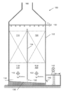
100221 In Figure 1, a gas processing column 100 is shown having an outer
housing
102. The column 100 preferably includes at least first and second cells 110
and 120
disposed within the outer housing 102. However, it is contemplated that the
column
100 could optionally include three or more cells. Each of the first and second
cells
110 and 120 preferably comprises a gas-liquid contacting surface area 114 and
124,
respectively, such that each cell can clean or otherwise condition an incoming
gas.
3
CA 02910805 2015-10-29
WO 2014/178882
PCT/US2013/039545
100231 It is especially preferred that the first and second cells 110 and 120
are fluidly
coupled to one another via a shared common liquid space 130 (e.g., liquid can
flow
between the cells). In this manner, liquid can be shared between the cells 110
and 120
such as through opening 132. As shown in Figure 1, the first and second cells
110
and 120 are separated by a first wall 134 having opening 132 in a bottom
portion of
the first wall 134, such that liquid within each of the cells 110 and 120 can
flow to the
other cell via opening 132. Such a column 100 requires only a single train of
pumps
and piping leading to (e.g., liquid inlet 150) and from (e.g., fluid outlet
140 and pump
142) column 100, thereby optimizing plot area and reducing equipment count and
cost. To encourage passive movement of liquid from cell 110 to cell 120, it is
contemplated that one or both of cells 110 and 120 could include a downward-
sloping
floor 136.
100241 It is contemplated that column 100 can be constructed out of steel or
lined
concrete, although any commercially suitable materials could be used. Where
concrete is used, it is further contemplated that the concrete could be lined
with
plastic, tile or other impervious inert material.
100251 A fluid outlet 140 can be coupled to the second cell 120, such that
fluid from
both of the first and second cells 110 and 120 can exit via the fluid outlet
140. This is
advantageous as it reduces the complexity of conduits from the column 100 by
eliminating the need to have separate outlet conduits for each cell, while
also reducing
the total number of pumps and other components required.
100261 Preferably, fluid outlet 140 comprises at least one pump 142 to
facilitate
removal of liquid from the column 100. In some contemplated embodiments, pump
142 can be a vertical can pump to minimize the vessel skirt height and
eliminates
suction piping and valves.
100271 The multi-celled column 100 typically will have as many gas inlets as
cells.
Thus, as shown in Figure 1, each of first and second cells 110 and 120
includes a gas
inlet 112 and 122, respectively.
100281 Advantageously, column 100 minimizes plot space as compared with prior
configurations of columns, while also offering operational flexibility because
each of
the cells can be independently operable, such that not all of the cells must
be operated
4
CA 02910805 2015-10-29
WO 2014/178882
PCT/US2013/039545
simultaneously. This allows for very low turn-down rates. For example, the
multi-
cell column 100 can be easily turned down by shutting down one or more of
cells 110
and 120. In this matter, a carbon dioxide capture plant capacity can be
changed to
match varying power plant loads.
100291 The cells 110 and 120 arc preferably constructed in a modular style
simplifying retrofitting or capacity increases by adding additional cells to
the existing
system. These additional cells can advantageously utilize the existing fluid
inlets and
outlets of the existing cells, reducing the need for additional equipment and
plot
space.
100301 Column 100 can further include one or more exhaust outlets 160. As
shown in
Figure 1, outlet 160 can be fluidly coupled to each of the first and second
cells 110
and 120, although each of the cells could alternatively have its own outlet.
100311 Figure 2 illustrates a gas processing system 200 having four cells 210A-
210D
arranged in a side-by-side cluster, although it is also contemplated that the
cells could
be arranged in-line. Although not shown, each of the cells 210A-2101) can
include a
gas inlet 212. A common liquid space 230 can fluidly couple the cells 210A-
210D to
one another, as well as to fluid outlet 240. Cells 210A-210B could be fluidly
coupled
via opening 232 in the wall dividing cell 210A from cell 210B. The cell walls
can
include additional openings allowing for the cells 210A-210D to be fluidly
coupled
with one another.
100321 Alternatively, it is contemplated that cells 210A-210B could be fluidly
coupled to one another and to fluid outlet 240, and cells 210C-210D could be
fluidly
coupled to one another and to a second fluid outlet.
100331 Cell 210A can include a liquid inlet, which feeds a fluid to
distributors 250
disposed within cell 210A. It is further contemplated that the liquid inlet
could also
feed fluid to cells 210C, and potentially cells 210B and 210D, to reduce the
number of
liquid inlets required. In other contemplated embodiments, the cells could
have two
or more liquid inlets. For example, cells 210A and 210C could share fluid from
a first
liquid inlet, while cells 210B and 210D could share fluid from a second liquid
inlet.
100341 The cells 210A-210D could share one or more exhaust outlets. As shown
in
Figure 2, cells 210A-210B could share a first exhaust outlet 260, while cells
210C-
CA 2910805 2017-04-28
WO 2014/178882
PCT/US2013/039545
210D could share a second exhaust outlet 262. Alternatively, each of the cells
could
have its own exhaust outlet that may or may not feed to a common exhaust duct.
[0035] Figures 3A-3B illustrate another embodiment of a gas processing system
300,
having a plurality of cells 310A-310N disposed in an in-line fashion, although
it is
contemplated that some of the cells could be grouped, such as in a side-by-
side cluster
of columns having cells, for example. The system 300 could further include
multiple
columns, each of which comprises at least two cells that are fluidly coupled
to each
other.
[0036] As shown in Figure 3A, the cells 310A-310N can be fluidly coupled via a
common liquid space 330, and fluid is allowed to flow from one cell to an
adjacent cell
via openings 332 in a wall dividing adjacent cells. Alternatively, though less
preferred,
piping or other components could be used to move liquid from cell to cell.
=
[0037] Each of the cells 310A-310N have a gas-liquid contacting system 314A-
314N,
respectively, which could be used for, for example, carbon capture, direct
contact
cooling or other gas treating processes.
[0038] The cells 310A-310N can further include a shared liquid distributor 350
configured to distribute a liquid within at least a portion of each of the
cells 310A-
310N, as well as a shared exhaust conduit 360. However, it is contemplated
that the
cells 310A-310N could be separated into sets of one or more cells, each of
which
includes a separate liquid inlet / distributor and/or exhaust conduit,
[0039] Figure 4 illustrates another embodiment of a gas processing system 400
having
a column that includes first and second cells 410A-410B. As shown in dashed
lines, the
system 400 can be constructed in a modular style, allowing for easy retrofits
or
increases of the system's capacity by increasing the number of cells or
varying the
number of cells in operation at a given time. The la ter-added cells can be
fluidly
coupled to the existing cells 410A-410B via a common liquid space, and thereby
utilize
the fluid outlet of the existing cells without requiring the need for
additional equipment
and much space outside of that shown in Figure 4.
[0040] Figure 5 illustrates one embodiment of a method for processing gas. In
step 510,
a flue gas stream is fed to first and second cells that are disposed in a
common
6
CA 02910805 2015-10-29
WO 2014/178882
PCT/US2013/039545
housing and share a common liquid space. The housing could include three or
more
cells depending on the requirements of the system.
100411 The first and second cells share a common gas outlet in step 512, and
each of
the first and second cells comprises a carbon capture system in step 514. It
is further
contemplated that one or both of the cells could include a direct contact
cooler. In
step 516, the common liquid space comprises a liquid reservoir disposed at a
bottom
portion of the common housing.
100421 In step 520, a liquid is injected into each of the first and second
cells via a
shared first liquid inlet. At least a portion of the liquid can advantageously
be
removed from the second cell via the common liquid space and a fluid outlet
coupled
to the first cell in step 530. This eliminates the need for separate fluid
outlets for each
of the cells, reducing the overall footprint of the system.
100431 Optionally, in step 540, operation of gas processing equipment in the
second
cell can be shut down as a function of a volume of flue gas to be processed.
Thus, for
example, the power requirements of the system can be reduced when there is a
lower
volume of gas to be processed and subsequently raised as the volume of flue
gas
increases.
100441 in some embodiments, the numbers expressing quantities of ingredients,
properties such as concentration, reaction conditions, and so forth, used to
describe
and claim, certain embodiments of the invention are to be understood as being
modified in some instances by the term "about." Accordingly, in some
embodiments,
the numerical parameters set forth in the written description and attached
claims are
approximations that can vary depending upon the desired properties sought to
be
obtained by a particular embodiment. In some embodiments, the numerical
parameters should be construed in light of the number of reported significant
digits
and by applying ordinary rounding techniques. Notwithstanding that the
numerical
ranges and parameters setting forth the broad scope of some embodiments of the
invention are approximations, the numerical values set forth in the specific
examples
are reported as precisely as practicable. The numerical values presented in
some
embodiments of the invention may contain certain errors necessarily resulting
from
the standard deviation found in their respective testing measurements.
7
CA 02910805 2015-10-29
WO 2014/178882
PCT/US2013/039545
100451 As used in the description herein and throughout the claims that
follow, the
meaning of "a," "an," and "the" includes plural reference unless the context
dearly
dictates otherwise. Also, as used in the description herein, the meaning of
"in"
includes "in" and "on" unless the context clearly dictates otherwise.
100461 The recitation of ranges of values herein is merely intended to serve
as a
shorthand method of referring individually to each separate value falling
within the
range. Unless otherwise indicated herein, each individual value is
incorporated into
the specification as if it were individually recited herein. All methods
described
herein can be performed in any suitable order unless otherwise indicated
herein or
otherwise clearly contradicted by context. The use of any and all examples, or
exemplary language (e.g. "such as") provided with respect to certain
embodiments
herein is intended merely to better illuminate the invention and does not pose
a
limitation on the scope of the invention otherwise claimed. No language in the
specification should be construed as indicating any non-claimed element
essential to
the practice of the invention.
100471 Groupings of alternative elements or embodiments of the invention
disclosed
herein are not to be construed as limitations. Each group member can be
referred to
and claimed individually or in any combination with other members of the group
or
other elements found herein. One or more members of a group can be included
in, or
deleted from, a group for reasons of convenience and/or patentability. When
any such
inclusion or deletion occurs, the specification is herein deemed to contain
the group as
modified thus fulfilling the written description of all Markush groups used in
the
appended claims.
100481 As used herein, and unless the context dictates otherwise, the term
"coupled
to" is intended to include both direct coupling (in which two elements that
are coupled
to each other contact each other) and indirect coupling (in which at least one
additional element is located between the two elements). Therefore, the terms
"coupled to" and "coupled with" are used synonymously.
100491 It should be apparent to those skilled in the art that many more
modifications
besides those already described are possible without departing from the
inventive
concepts herein. The inventive subject matter, therefore, is not to be
restricted except
in the scope of the appended claims. Moreover, in interpreting both the
specification
8
CA 02910805 2015-10-29
WO 2014/178882
PCT/US2013/039545
and the claims, all terms should be interpreted in the broadest possible
manner
consistent with the context. In particular, the terms "comprises" and
"comprising"
should be interpreted as referring to elements, components, or steps in a non-
exclusive
manner, indicating that the referenced elements, components, or steps may be
present,
or utilized, or combined with other elements, components, or steps that are
not
expressly referenced. Where the specification claims refers to at least one of
something selected from the group consisting of A, B, C .... and N, the text
should be
interpreted as requiring only one element from the group, not A plus N, or B
plus N,
etc.
9