Note: Descriptions are shown in the official language in which they were submitted.
CA 02911143 2015-11-05
APPARATUS, SYSTEM, AND METHOD FOR DETECTING THE PRESENCE AND
CONTROLLING THE OPERATION OF MOBILE DEVICES WITHIN A VEHICLE
This application is a divisional of Canadian Patent Application No. 2,824,477
filed January 13,
2012.
BACKGROUND
Mobile devices such as wireless devices, including, for example, cellular
telephones,
smart phones, laptop computers, notebook computers, tablet devices (e.g., iPad
by Apple())
are ubiquitous in modern society. Use of such mobile devices while operating a
vehicle,
however, can be hazardous. The problem is exacerbated for inexperienced
operators of the
vehicle, such as youngsters just learning how to drive. Rates of vehicular
accidents where
mobile devices are involved are rising, especially with teenagers. Text
messaging while
operating a moving vehicle can be dangerous and has been linked with causing
accidents.
More generally, operating any keyboard while operating a vehicle can be
dangerous.
Thus, the widespread adoption of mobile devices and common use of the devices
while driving has raised concerns about the distraction of drivers. A driver
speaking or text
messaging on a mobile telephone may become mentally distracted from driving
and lose
control of the vehicle that he or she is driving. Thus, it is not uncommon to
see an individual
involved in an accident who was speaking or text messaging on a mobile device
rather than
paying attention to the road. Studies now suggest that individuals speaking on
mobile
telephones while driving a car may be as impaired as a person who drives while
intoxicated.
Not only is the driver mentally distracted, but eyes of the driver are
diverted for dialing,
looking to see who an incoming call is from.
It would be highly desirable to detect the presence of a mobile device such as
a
wireless device within a vehicle and control or disable the operation of the
mobile device.
SUMMARY
In one embodiment, a method for determining the presence of a mobile device
located in a predetermined detection zone within a vehicle is provided. A
detection module
receives a communication signal. The detection module determines that the
communication
signal was transmitted by a mobile device located within a predetermined
detection zone
within a vehicle. A control module transmits a control signal to the mobile
device located
within the predetermined detection zone.
FIGURES
FIG. 1 illustrates a vehicle that includes a cabin for accommodating an
individual in a
driver seat.
1
CA 02911143 2015-11-05
FIG. 2 illustrates one embodiment of a mobile device detection and control
system.
FIG. 3 illustrates one embodiment of a power sensor circuit for detecting the
energy
radiated by the electromagnetic signal transmitted by the mobile device.
FIG. 4 illustrates one embodiment of a power sensor circuit comprising a
tuning
circuit with a scanner in series with the antenna.
FIG. 5 illustrates a schematic diagram of a multi-band detector for monitoring
uplink
activity of the mobile device.
FIG. 6 illustrates an interior portion of the vehicle comprising one
embodiment of the
mobile device detection and control system located within the dashboard of the
vehicle.
FIG. 7 illustrates one embodiment of a logic diagram for determining the
presence of
a mobile device located in a predetermined detection zone within a vehicle.
DESCRIPTION
The present disclosure describes embodiments of an apparatus, system, and
method
for detecting the presence of a mobile device such as a wireless device and
controlling or
disabling the operation of the mobile device when it is detected. In
particular, the present
disclosure is directed to embodiments of an apparatus, system, and method for
detecting the
presence of a mobile device such as a wireless device in a predetermined
location within a
vehicle and disabling some or all of the functions of the mobile device when
it is detected in
the predetermined location. More particularly, the present disclosure is
directed to
automatically preventing a person in the driver's seat of a vehicle from text
messaging and
doing other similar excessively dangerous activities with the mobile device.
It is to be understood that this disclosure is not limited to particular
aspects or
embodiments described, as such may vary. It is also to be understood that the
terminology
used herein is for the purpose of describing particular aspects or embodiments
only, and is
not intended to be limiting, since the scope of the apparatus, system, and
method for
detecting the presence of a mobile device within a vehicle and controlling the
operation of
the mobile device when it is detected is defined only by the appended claims.
In one embodiment, the present disclosure provides an apparatus, system and
method for detecting and restricting the use of mobile devices within a
vehicle, whether the
vehicle is moving or stationary. Mobile devices, such as wireless devices, may
include
without limitation, for example, cellular telephones, smart phones, laptop
computers,
notebook computers, tablet devices (e.g., iPad by Apple ), Netbook , among
other wireless
mobile devices that a user can interact with while located in a vehicle. In
one embodiment,
the presence of a mobile device in the driver's side area of the vehicle is
detected by at least
one sensor located within the vehicle. When the presence of the mobile device
is detected,
the operation of the mobile device is controlled, disabled, or modified with
respect to the
2
CA 02911143 2015-11-05
person located in the driver side area of the vehicle but not with respect to
other persons
located in other areas of the vehicle.
FIG. 1 illustrates a vehicle 100 that includes a cabin 104 for accommodating
an
individual in a driver seat 106. It will be appreciated in accordance with the
present
disclosure that the term vehicle is used broadly and is meant to include any
kind of
transportation vehicle. For example, the vehicle 100 may be any type of
automobile, truck,
sport utility vehicle, aircraft, watercraft, spacecraft, or any other means of
transportation, or
combinations thereof, where communications by the driver using a mobile device
is to be
detected and controlled.
Disposed on or within the dashboard 108 of the vehicle 100 is a mobile device
detection and control system 102. In one embodiment, the mobile device
detection and
control system 102 is configured to detect the presence of a mobile device
located in the
driver seat 106 side of the vehicle 100 and control the operation of the
mobile device by
either jamming the mobile device, jamming certain functions or aspects of the
mobile device,
or redirecting the operation of the mobile device to a hands-free alternate
system. In other
embodiments, at least some elements or components of the mobile device
detection and
control system 102 may be located in other areas of the vehicle 100.
It may be desirable to place detection and jamming elements of the mobile
device
detection and control system 102 as close to the driver as possible. For
example, sensors
and directional antennas of the mobile device detection and control system 102
may be
located in proximity of the driver seat 106. This configuration provides the
more precise
detection of the presence of the mobile device in the driver seat 106 side of
the vehicle 100
and prevents interference with other mobile devices or other persons located
within the
vehicle 100 to allow persons in the passenger seats to use the mobile device
while the driver
is unable to. Other elements or components such as control logic may be
located in other
locations of the vehicle 100 away from the driver seat 106.
In one embodiment, the mobile device detection and control system 102 is
configured to detect signal transmissions from mobile devices located in or
proximity of a
detection zone. In accordance with the described embodiments, the detection
zone is
defined as a zone substantially in or in proximity of the driver seat 106 side
of the vehicle
100. In other embodiments, however, the detection zone may be any predefined
zone within
the vehicle 100, without limitation. In one aspect, the detection portion of
the mobile device
detection and control system 102 may tuned to detect signal transmissions in
frequency
bands used by conventional mobile telephones operating in common cellular
channels.
Once the signals are detected, the mobile device detection and control system
102
wirelessly controls the operation of the mobile device in one or more ways.
For example, in
one embodiment, the mobile device detection and control system 102 transmits
control
3
CA 02911143 2015-11-05
signal to disable the operation of the mobile device by way of jamming signals
that interfere
with the communication mechanism of the mobile device. While the jamming
signals are
transmitted, the mobile device or other communication device within the
detection zone is
rendered either inoperable or operable only in a state of limited capacity.
The jamming
signals forcibly interfere with the communication mechanism of the mobile
device by
broadcasting noise or other signals on one or more channels used by the mobile
device. In
other embodiments, a jamming signal may be interpreted by the mobile device to
disable
one or more functions of the mobile device. In such an embodiment, the jamming
signal
may be communicated to the mobile device through a secondary channel, such as
a
Bluetooth wireless connection or any other connection that is secondary to the
primary
cellular communication channel. In some embodiments, the jamming module may
communicate on the primary communication channel of the mobile device only or
in addition
to one or more secondary channels.
Accordingly, the mobile device detection and control system 102 can either
completely block the ability to receive or send a call on a mobile device, or
sufficiently
interfere with the mobile device signal so as to make the mobile device usage
undesirable.
For example, if the jamming signal simply interrupts a sufficient portion of
the conversation,
the user will simply either postpone the conversation or pull over so the
conversation can
continue uninterrupted. In another embodiment, the mobile device detection and
control
system 102 may disable the operation of certain components or functions of the
mobile
device. For example, the keyboard portion of the mobile device may be jammed
to prevent
the user from using the text messaging function of the mobile device. In
another
embodiment, the mobile device detection and control system 102 may direct the
operation of
the mobile device to a hands-free operation. These and other embodiments are
discussed
in more detail hereinbelow.
In one embodiment, the mobile device detection and control system 102
initiates the
detection process by transmitting probing signals to detect the presence of a
mobile device
within a detection zone. Once the probing signals are transmitted, the
detection and control
system 102 waits for an echo signal reflected by the mobile device or a
response signal
transmitted by the mobile device. If the detection and control system 102
detects the echo
signal or a transmission by the mobile device, the detection and control
system 102
transmits a control signal to control the operation of the mobile device. For
example, in one
embodiment, the detection and control system 102 transmits a control signal to
disable the
operation of the mobile device by way of jamming signals that interfere with
the
communication mechanism of the mobile device. In another embodiment, the
detection and
control system 102 may reroute communications to a hands-free system, such as
a
Bluetooth communication system.
4
CA 02911143 2015-11-05
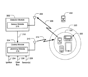
FIG. 2 illustrates one embodiment of a mobile device detection and control
system
102. In one embodiment, the mobile device detection and control system 102 is
configured
to detect the presence of a mobile device 200 located in or in proximity of
the driver seat 106
area of the vehicle 100. Once the mobile device 200 is detected, the mobile
device
detection and control system 102 is configured to control the operation of the
mobile device
200. In one embodiment, the mobile device detection and control system 102
comprises a
detector module 202 and a control module 204 coupled to the detector module
202. The
detector module 202 comprises a multi-band antenna 208 to receive signal
transmissions
from the mobile device 200 and the control module 204 comprises an antenna 210
to
transmit control signal to the mobile device 200. In various embodiments, the
detector
module 202 and the control module 204 may share an antenna when these
components are
located in proximity of each other.
In various embodiments, the mobile device 200 may be implemented as a handheld
portable device, computer, mobile telephone, sometimes referred to as a
smartphone, tablet
personal computer (PC), laptop computer, or any combination thereof. Examples
of
smartphones include, for example, Palm products such as Palm Treo
smartphones
(now Hewlett Packard or HP), Blackberry smart phones, Apple iPhone ,
Motorola
Droide, and the like. Tablet devices include the iPad tablet computer by
Apple and more
generally a class of lightweight portable computers known as Netbooks. In some
embodiments, the mobile device 200 may be comprise, or be implemented as, any
type of
wireless device, mobile station, or portable computing device with a self-
contained power
source (e.g., battery) such as a laptop computer, ultra-laptop computer,
personal digital
assistant (PDA) with communications capabilities, cellular telephone,
combination cellular
telephone/PDA, mobile unit, subscriber station, user terminal, portable
computer, handheld
computer, palmtop computer, wearable computer, media player, pager, messaging
device,
data communication device, and so forth.
In one embodiment, the detector module 202 is configured to detect presence of
the
mobile device 200 located within a detection zone 220 defined as a three-
dimensional zone
within or in proximity of the driver seat 106. Methods of detecting the
presence of the mobile
device 200 may vary based on the wireless technology communication standards
used by
the mobile device 200. Examples of wireless technology communication standards
that may
be used In the United States, for example, may include Code Division Multiple
Access
(CDMA) systems, Global System for Mobile Communications (GSM) systems, North
American Digital Cellular (NADC) systems, Time Division Multiple Access (TDMA)
systems,
Extended-TDMA (E-TDMA) systems, Narrowband Advanced Mobile Phone Service
(NAMPS) systems, 3G systems such as Wide-band CDMA (WCDMA), 4G systems, CDMA-
2000, Universal Mobile Telephone System (UMTS) systems, Integrated Digital
Enhanced
5
CA 02911143 2015-11-05
Network (iDEN) (a TDMA/GSM variant) and so forth. These wireless
communications
standards are fully familiar to those of ordinary skill in the art. The
frequency and signal
strength of the radio frequency (RF) signals transmitted by the mobile device
200 depend on
the network type and communication standard. The detector module 202 detects
the RF
signal, or simply electromagnetic energy radiation, transmitted by the mobile
device 200,
generally speaking. Accordingly, in one embodiment, the detector module 202
may be
configured to lock onto specific cellular frequencies or cellular frequency
bands or may be
configured to scan all the available cellular frequencies or cellular
frequency bands and lock
onto the RF signal emitted by the mobile device 200.
In one embodiment, the detector module 202 may comprise a sensor module 216
coupled to the multi-band antenna 208. The sensor module 216 may be tuned to
detect
energy at a predetermined signal strength in the electromagnetic signal 206,
e.g., RF signal,
emitted by the mobile device 200 and received by the antenna 208. (twill be
appreciated
that the signal strength or power of the energy radiated by the
electromagnetic signal 206
emitted by the mobile device 200 will be greatest when the mobile device 200
is making an
outbound call or otherwise communicating with a cellular base station (e.g.,
searching for
base station signals or in contact with a base station or cell). Very little
energy in the
electromagnetic signal 206 is radiated when the mobile device 200 is turned
off or when it is
not communicating with the cellular base station. In the latter case, when the
mobile device
200 is turned on but is not communicating with the cellular base station, the
mobile device
200 possibly may be detected only if the detector module 202 comprises
extremely sensitive
components. Most conventional mobile devices 200 radiate energy at a power
level ranging
from about 0.5 milliwatts (mW) to about several hundred mW. A detector module
202 of
suitable sensitivity can be configured to detect electromagnetic signals 206
in this range of
power level. Many radio electronic equipment are capable of detecting low-
level power in
the electromagnetic signal 206 and is one reason why airlines are very
sensitive about
electronic equipment that operates at key points of the flight, why some
electronic equipment
should be turned off near blast sites, and why cellular phones should be
turned off around
some types of hospital equipment.
It is well known that a mobile device 200, such as, for example, a cellular
telephone
using the GSM standard, generates detectable radio interference. It is well
known to users
of GSM cellular telephones that if the cellular telephone is used in the
vicinity of an electronic
device (such as, for example, a radio receiver, stereo system, N set, a
wired/fixed
telephone or even another GSM cell phone), the radio transmissions from the
GSM cell
phone may be inadvertently "picked up" by the electronic device and a signal
proportional to
the envelope of the radio transmission may be produced inside the electronic
device. In fact,
this typically unwanted signal may even disrupt the operation of the
electronic device. For
6
CA 02911143 2015-11-05
example, it is particularly well known that GSM cellular telephones present a
potential
hazard for wearers of heart pacemakers, as the GSM signal may disrupt proper
pacemaker
operation if the phone is very near to the wearer's chest.
In one embodiment, the sensor module 216 is configured to exploit the
detectable
radio interference of the electromagnetic signal 206 generated by the mobile
device 200
when it is communicating with the cellular base station. When the sensor
module 216 of the
detector module 202 detects the electromagnetic signal 206, it assumes the
presence of a
mobile device 200 located within the detection zone 220, i.e., in or in
proximity of the driver
seat 106, and communicates a signal 212 to the control module 204. Disposed in
communication with the control module 204 is a jamming module 218. In one
embodiment,
when the control module 204 receives the signal 212 from the detection module,
the
jamming module 218 transmits a jamming signal 214 via the antenna 210 that is
detectable
only by the mobile device 200 when located in the detection zone 220. In
various
embodiments, the electromagnetic jamming signal 214 may be a signal that
disables the
operation of the mobile device 200, may disable certain functionality of the
mobile device
200, or may redirect the operation of the mobile device 200 to a hands-free
operation. The
control module 204 may be disposed in communication with a system of the
vehicle 100,
such as the ignition system 224, the gear box 226, or a variety of sensors
228. The control
module 204 logic then monitors a function of a system of the vehicle 100 in
addition to the
detection of the presence of the mobile device 200. Accordingly, the jamming
module 218
would be activated only when a monitored function of the vehicle 100 is
activated. For
example, when the sensor module 216 detects the presence of a mobile device
200 in the
detection zone 220, the jamming module 218 would be activated only when the
vehicle 100
is turned on, when the vehicle 100 is moved out of park or otherwise put in
gear, or when
one or more sensors detect that the operation of the vehicle 100.
In one embodiment, the sensor module 216 may comprise an energy harvester to
harvest the energy in the electromagnetic signal 206 transmitted by the mobile
device 200.
The energy harvester receives the radiated energy at the antenna 208 and
converts the
energy into a voltage potential to energize the detector module 202 and
communicate the
signal 212 to the control module 204. In other embodiments, the energy
harvester may be
separate from the sensor module 216 and the voltage potential produced by the
energy
harvester may be used to energize the sensor module 216. In any embodiment,
the voltage
potential produced by the energy harvester is employed to determine the
presence of a
mobile device 200 in the detection zone 220. Accordingly, the sensitivity of
the sensor
module 216 is adjusted such that the energy harvester is sensitive only to the
radiated
energy levels that typically occur when the mobile device 200 is located
within the detection
zone 220 and not sensitive to electromagnetic energy transmitted by mobile
devices 222
7
CA 02911143 2015-11-05
located outside the detection zone 220. In this manner, passengers can freely
use their
mobile devices 222 outside the detection zone 220 without triggering the
detector module
202.
In other embodiments, the detector module 202 may be coupled to the electrical
system of the vehicle 100 and powered by the vehicle battery, or may be
powered by a
separate battery. In such embodiments, the detector module 202 comprises a
frequency
scanning and power level measurement module that measures the power of the
electromagnetic signal 206 transmitted by the mobile device 200. Accordingly,
the sensitivity
of the detector module 202 can be tuned to trigger the detection signal 212
when the
detector module 202 detects transmit power levels that correspond to the
mobile device 200
being located in the detection zone 220 without triggering the detection
signal 212 for
transmit power levels corresponding to the mobile devices 222 located outside
the detection
zone 220. This may be accomplished by strategically locating a directional
multi-band
antenna 208 such that it is maximally sensitive to transmit power level
radiated by the mobile
device 200 located in the detection zone 220 and minimally sensitive to
transmit power
levels to the mobile devices 222 located outside the detection zone 220.
In one embodiment, the control module 204 may comprise a communications
jamming module 218 coupled to the antenna 210. The jamming module 218 is
disposed in
communication with the antenna 210. The antenna 210 emits a jamming signal 214
to
thereby disrupt mobile device 200 signals and prevent or otherwise interfere
with the ability
to make or receive calls with the mobile device 200. The jamming module 218
and the
antenna 210 may be powered by the electrical system of the vehicle 100, or may
be
powered by a separate battery. The jamming module 218 may be any device that
transmits
a jamming signal 214 that causes interference or inoperability of the mobile
device 200. In
some embodiments, the jamming module 218 may broadcast noise or a specialized
signal
that is selected to interfere with one or more of the communications
frequencies of the
mobile device 200. For example, the jamming module 218 may broadcast noise or
a
repeated interfering signal on the control channel frequencies for a cellular
phone system. In
some embodiments, the jamming module 218 may transmit on a narrow frequency
band,
while in other embodiments a very broad frequency band may be selected. The
precise
method for interfering with the mobile device 200 by the jamming module 218 is
dependent
on the transmission and reception characteristics of the mobile device 200.
Those skilled in
the art may use any appropriate jamming module 218 for any specific mobile
device 200
device contemplated.
In accordance with one aspect, the jamming module 218 may be mounted in the
vehicle 100. When activated, the jamming module 218 inhibits the ability to
send or receive
a mobile telephone call with a mobile terminal 200 located in the detection
zone 220.
8
CA 02911143 2015-11-05
Depending on the wattage of the jamming module 218 (or the use of a
directional antenna),
the zone in which the mobile device 200 is jammed may be controlled. Thus, for
example,
the jamming module 218 may be set to effectively jam telephone calls to or
from the mobile
device 200 for a space of 1-3 feet from the location of the jamming device
218, or in a
direction which interferes with the ability of the driver to receive a
telephone call, place a
telephone call, or send a text message but not interfere with other
passengers' ability to
receive or initiate mobile telephone calls or send test messages.
In one embodiment, the antenna 210 may be positioned under the dashboard of
the
vehicle 100 or up on the driver side windshield. Alternatively, a directional
antenna could be
placed in the driver's seat to interfere with the driver making calls or
sending text messages.
In one embodiment, the control module 204 may be used to prevent
communications
by the operator of the vehicle 100 when the mobile device 200 is detected in
the detection
zone 220 in combination with either an ignition switch, transmission switch,
or other
vehicular sensor mechanism. In one embodiment, an ignition switch may be
monitored to
cause the jamming module 218 to broadcast only when a mobile device 200 is
detected in
the driver seat 106 side of the vehicle 100 and the ignition switch is turned
on, which would
require the operator of the vehicle 100 to shut down the vehicle 100 to
establish outside
communications. The jamming module 218 would prevent any further
communications until
the vehicle 100 was switched off. In another embodiment, the jamming module
218 may be
activated only when a mobile device 200 is detected in the detection zone 220
and an
automatic transmission in the vehicle 100 is moved out of "park" and into a
position where
the vehicle 100 may move. When such a system is in place, the operator of the
vehicle 100
must stop the vehicle 100 and either move the transmission to "park" or turn
off the engine to
operate the mobile device 200.
In one embodiment, the jamming module 218 may be configured to operate within
the confines of the vehicle 100. In some cases, the antenna 210 coupled to the
jamming
module 218 of the control module 204 may be configured with a predetermined
power level
and directional attributes to direct the jamming signals 214 merely in the
detection zone 220
such that other occupants of the vehicle 100 can continue to operate other
mobile devices
222. In such cases, the jamming signals 214 may be generally confined within
the detection
zone 220 of the vehicle 100. In some embodiments, the jamming signals 214 may
be
localized to other areas within the vehicle 100 so that operation of a mobile
device in that
area is disabled, but leaving other mobile devices outside of that area
operational.
In various embodiments, the antenna 210 and power level of the jamming signal
214
may be configured to deliver the jamming signal very precisely to the
detection zone 220. In
one embodiment, this may be implemented with a directional antenna located
within the
vehicle 100 where maximum jamming is delivered to the detection zone 220 and
minimal
9
CA 02911143 2015-11-05
jamming power is delivered outside the jamming zone 220. In such embodiments,
the
detector module 202 may be configured to indiscriminately detect any
transmissions from all
mobile devices 200, 222 within the vehicle 100 and the jamming module 218
would only
transmit jamming signals to the detection zone 220 to jam the mobile device
200 within the
detection zone 220 without affecting he mobile devices 22 outside the
detection zone 220.
Such implementation would not care whether or not a mobile device is located
within the
detection zone 220, thus simplifying the design of the detector module 202.
In one embodiment, the jamming module 218 may permit incoming calls to the
mobile device 200 but prohibit outgoing calls to the mobile device 200. When
the detector
module 202 detects the energy in the electromagnetic signal 206 from an
attempted
outgoing call by the mobile device 200, the signal 212 activates the jamming
signal 214. In
such an embodiment, the detector module 202 may comprise additional modules to
discern
the identity of the mobile device 200 and enable the control module 204 to
transmit the
jamming signal 214 after the identity of the mobile device 200 is confirmed.
In other embodiments, the sensor module 216 may be used to detect and permit
or
deny any type of operation of the mobile device 200. For example, calls may be
received by
the mobile device 200 but placed calls may be jammed. In another example, some
calls,
such as emergency calls, may be permitted to be placed while other outgoing
calls are
jammed. Any other function of the mobile device 200 that may be detected may
be
selectively permitted or disabled by the jamming module 218.
In one embodiment, the mobile device 200 may receive the jamming signal 214
and
operate in a reduced function mode. For example, the mobile device 200 may be
prohibited
from initiating a phone call except for emergency calls to 911. In another
example, the
mobile device 200 may be permitted to receive all calls or calls from a
predefined list of
callers while being prohibited from placing calls. Various reduced function
modes may be
used and in some embodiments a setting may define the precise operations
allowed.
In one embodiment, control module 204 initiates the detection process by
transmitting probing signals to detect the presence of a mobile device 200
within a detection
zone 220. Once the probing signals are transmitted, the detector module 202
waits for an
echo signal reflected by the mobile device 200 or a response signal
transmitted by the
mobile device 200. If the detector module 202 detects the echo signal or a
transmission by
the mobile device 200, the control module 204 transmits a control signal to
control the
operation of the mobile device 200. For example, in one embodiment, jamming
module 218
transmits a control signal to disable the operation of the mobile device 200
by way of
jamming signals 214 that interfere with the communication mechanism of the
mobile device
200. In another embodiment, the control module 204 may reroute communications
to a
hands-free system, such as a Bluetooth communication system.
CA 02911143 2015-11-05
FIG. 3 illustrates one embodiment of a power sensor circuit 300 for detecting
the
energy radiated by the electromagnetic signal 206 transmitted by the mobile
device 200.
The illustrated power sensor circuit 300 is one embodiment of a sensor module
216
described in connection with FIG. 2. The power sensor circuit 300 also
converts the energy
in the radiated electromagnetic signal 206 to a voltage potential indicative
of the location of
the mobile device 200. In the illustrated embodiment, the power sensor circuit
300 is not
connected to the power source of the vehicle 100 or to a separate battery.
Rather, the
power sensor circuit 300 is one implementation of an energy harvester circuit
which derives
its power only from the energy radiated by the electromagnetic signal 206
transmitted by the
mobile device 200. The electromagnetic signal 206 detected by the antenna 208
is filtered
by tuning circuit 306 to match the most common frequency bands used by mobile
devices.
In one embodiment, the tuning circuit 306 may comprise an inductor L and a
capacitor C
selected to tune the power sensor circuit 300 to the desired frequency band.
Those skilled
in the art will appreciate that the tuning circuit may be implemented using
digital or analog
tuning techniques and therefore the embodiment disclosed in FIG. 3 is not
limiting.
The diode Drf is an RF diode and acts to partially rectify the electromagnetic
signal
206 received by the antenna 208 and tuned by the L-C circuit. The output of
the RF diode
charges a capacitor Co to a predetermined potential Vd. Thus, the power sensor
circuit 300
converts the radiated electromagnetic signal 206 to a voltage potential Vd
that corresponds
to the location of the mobile device 200 within the vehicle 100. With
reference now to both
FIGS. 2 and 3, when the voltage potential Vd across the output capacitor Co
exceeds a
predetermined level, it indicates the presence of a mobile device 200 within
the detection
zone 220. The voltage potential Vd is compared to a threshold voltage Vt by a
comparator
306. The threshold voltage Vt is predetermined as the voltage level
corresponding to the
mobile device 200 being located in the detection zone 220. The output of the
comparator
306 is provided to a detection logic module 304, which may be part of the
detector module
202. The detection logic module 304 then generates a detection signal 212 and
communicates the detection signal 212 to the control module 204. Upon
receiving the
detection signal 212, the control module 204 activates the jamming module 218
to interfere
with the operation of the mobile device 200. As previously discussed, in
certain
embodiments, the jamming module 218 may be activated only if other logical
conditions are
met such as the state of the ignition system, the gear box, or other sensors.
Still with reference to FIGS. 2 and 3, it may be desirable to determine when
to shut
off the jamming module 218. Accordingly, in one embodiment, once the Vd signal
is
provided to the control module 204, the detection logic module 304 activates a
switch 302 to
discharge the output capacitor Co. Substantially at the same time, the jamming
circuit 218 is
turned off. If the mobile device 200 is still activated in the detection zone
220, the
11
CA 02911143 2015-11-05
electromagnetic signal 208 would be picked up by the antenna 208 to charge the
capacitor
C, and generate a voltage potential Vd to activate the jamming module 218.
This cycle
would be repeated until the mobile device 200 is either removed from the
detection zone 220
such that the radiated electromagnetic signal 208 is too weak to activate the
power sensor
circuit 300 or the mobile device 200 is deactivated or shut off such that
there is little or no
radiated electromagnetic signal 208.
In the embodiment illustrated in FIG. 3, the tuning circuit 306 may be
implemented to
have a bandwidth encompassing the most popular cellular telephone frequencies.
Since the
tuning circuit 306 is fixed, it is tuned to a wide frequency band to receive
electromagnetic
signals 208 from about 0.8 to about 2 GHz, as shown in TABLE 1 below. In other
embodiments, however, as described in connection with FIG. 4, the tuning
circuit 306 may
include a frequency band scanner to switch between multiple tuning elements
and scan the
detection zone 220 for multiple frequencies to more precisely tune the power
sensor circuit
300 to the appropriate frequency band of the mobile device 200 located in the
detection
zone 220.
FIG. 4 illustrates one embodiment of a power sensor circuit 400 comprising a
tuning
circuit 406 with a scanner 402 in series with the antenna 208. The scanner 402
is controlled
by the logic module 404 and sweeps multiple frequency bands. With reference
now to FIGS.
2-4, the logic module 404 periodically switches tuning elements Li, L2, Ln,
into the tuning
circuit 406 to monitor various frequency bands associated with the mobile
device 200
located in the detection zone 220. The voltage potential Vd is compared to a
threshold
voltage Vt by a comparator 406. The threshold voltage Vt is predetermined as
the voltage
level corresponding to the mobile device 200 being located in the detection
zone 220. In
other respects, the power sensor circuit 400 shown in FIG. 4 operates in a
manner similar to
the power sensor circuit 300 shown in FIG. 3.
FIG. 5 illustrates a schematic diagram of a multi-band detector 500 for
monitoring
uplink activity of the mobile device 200. In the illustrated embodiment, the
multi-band
detector 500 provides high-speed scanning of cell phone uplink frequency bands
for CDMA,
GSM, PCS, and WCDMA. An uni-directional multi-band antenna 508 receives
signals 506
from a mobile device located in the detection zone 220. A scanner 510
continuously scans
CDMA, GSM, PCS, and WCDMA frequency bands for mobile devices 200 located in
the
detection zone 220 that are in active or idle state. A detector module 502
provides a
detection signal 512 to the control module 504 for activating a jamming module
when a
signal 506 is detected, as previously discussed. The up-link frequencies
covered by the
multi-band detector 500 shown in FIG. 5 are listed in TABLE 1 below.
12
CA 02911143 2015-11-05
TABLE 1
Air Interface Frequency Band (MHz)
North America
824-849
GSM-850, GSM-900, CDMA, Cellular
890-915
GSM-1900/PCS-1900 1850-1910
European Union/Asia/Australia
E-GSM-900 880-915
GSM 1800 (DCS-1800) 1710.2-184.8
WCDMA/UMTS 1920-1980
The multi-band detector 500 may be implemented using a variety of components
to
detect radiated energy in the signal 506 received by the uni-directional multi-
band antenna
508 and make RF power measurements at low levels by the detector module 502 in
order to
detect the presence of a mobile device 200 in the detection zone 220. The RF
power level
may be measured directly or may be sampled. Recently, a number of integrated
RF power
detectors have become available, intended for wireless networking and mobile
telephone
applications. Since these integrated circuits are produced in high-volume
using integrated-
circuit technology, they are consistent and inexpensive ¨ often cheaper than
typical
microwave diodes, such as RF diode Dff shown in FIGS. 3 and 4. Many of them
are
specified for operation into the GHz region, covering several amateur
microwave bands, and
a few operate to 10 GHz and beyond.
In one embodiment, the RF power detector module 502 may be implemented with an
LTC5508 integrated circuit from Linear Technologies rated up to 7GHz, which is
well within
the bandwidth required for mobile devices frequency bands shown in TABLE 1.
This
integrated circuit requires operate a few milliamps at 3 to 5 volts and would
be connected to
the power supply of the vehicle or to a separate battery. An LT5534
logarithmic-amplifier
type detector rated up to 3 GHz with 60 dB of dynamic range may be employed to
amplify
the RF power signal detected by the LTC5508 integrated circuit.
The multi-band detector 500 may be employed to measure RF power transmitted by
the mobile device 200 and also antenna radiation pattern measurement. The
sensitivity of
the multi-band detector 500 may be useful for low-level power measurements as
an "RF
Sniffer" to detect RF leakage from the mobile device 200. The multi-band
detector 500
provides fast response so that it may be used to detect modulation and to
detect noise levels
from the multi-band antenna 506.
13
CA 02911143 2015-11-05
FIG. 6 illustrates an interior portion of the vehicle 100 comprising one
embodiment of
the mobile device detection and control system 102 located within the
dashboard 108 of the
vehicle 100. FIG. 6 illustrates three potential locations within the dashboard
108 where the
mobile device detection and control system 102 can be located. It will be
appreciated that
the detection and control system 102 may be located in one or more of these
locations on or
within the dashboard 108. It would be preferable that the detection and
control system 102
be located within the dashboard 108 to prevent user tampering. Accordingly,
the detection
and control system 102 is shown is phantom to indicate that the detection and
control
system 102 is located within the dashboard 108. In another embodiment, the
control module
203 may be configured with a data collection process to record a situation
when the
detection and control system 102 was deactivated by an owner of the vehicle
100 with or
without the help of a car mechanic. Such tamper recording and detection
feature may be
helpful in post accident investigations to determine if the detection and
control system 102
was disabled and thus voiding insurance coverage, for example.
With reference now to FIGS. 1-6, the mobile device detection and control
system 102
comprises a detector module 202 and a control module 204 coupled to the
detector module
202. The detector module 202 detects the presence of a mobile device 200
within the
detection zone 220 ("Discovery Umbrella"). When the detector module 202
detects the
presence of a mobile device 200 within the detection zone 220, the control
module 204
activates the jamming module 218, which transmits the control signal 214. The
control
signal 214 interferes with the operation of the mobile device 200 when it is
located within the
detection zone 220 without interfering with mobile devices 222 located outside
the detection
zone 220.
In one embodiment, the mobile device detection and control system 102 may be
triggered when the driver enters the vehicle 100. Upon being triggered, the
mobile device
detection and control system 102 is initialized and goes into detection mode
to establish a
no-communication system ("NoCom system"). The detection mode is a process
wherein the
mobile device detection and control system 102, through one or more sensor(s)
and logic
detects the presence of all electromagnetic signals 206 such as RF, Wi-Fi,
Cellular, and
Satellite communications signals from the mobile device 200. In one
embodiment, the
detection process is initiated by the mobile device detection and control
system 102, which is
not dependent upon a driver's interaction to initiate the detection process.
Decoupling the
process from the driver, young and old, is advantageous because it avoids
reliance on self
policing, which currently has failed to work even with laws presently enacted.
Thus, the
triggering condition may be the activation of a switch such as the ignition
switch 602 of the
vehicle 100 or deactivation of a "park" sensor 604 of an automatic
transmission of the
vehicle 100, among other sensors.
14
CA 02911143 2015-11-05
Accordingly, upon ignition of the vehicle 100, the mobile device detection and
control
system 102 would initiate the detection process via logic that controls the
operation of the
detection module 202 and the control module 204. In accordance with the
detection
process, logic would instruct the sensor module 216 to initiate sensing or
scanning for any
type of communication signals 206 emitted by the mobile device 200 within the
detection 220
within the driver side 106 area of the vehicle 100. In one embodiment, the
sensor module
216 may be located within the dashboard 108 console and or within a microphone
of a
hands-free set. This configuration would hide the sensor module 216 and
prevent drivers
from tampering with the mobile device detection and control system 102 by
blocking the
sensor module 216 or prevent activation of the detection process. In one
embodiment, the
sensor module 216 may be coupled to the ignition 602 to render the vehicle 100
inoperable if
the sensor module 216 is blocked.
The logic provides a detection process for detecting communication signals 206
emitted by the mobile device 200 located within the detection zone 220 to
prevent the driver
from adequately using the mobile device 200. The detection process will detect
and take
control of the driver side mobile device 200. The logic, however, will not
prevent passengers
from using their mobile devices 222 outside the detection zone 220.
Once the detection process is initiated, if the mobile device 200 is a smart
phone and
is detected within the detection zone 220, in one embodiment, the mobile
device detection
and control system 102 can automatically connect to the vehicle 100 hands-free
communication system. If no hands-free communication system is available, the
mobile
device 200 would be disabled by the control signals 214 transmitted by the
jamming module
218. Nevertheless, the mobile device detection and control system 102 would
always allow
emergency 911 calls.
Additionally, once the detection process is initiated, if the mobile device
200 is a
smart phone and is detected within the detection zone 220, in one embodiment,
the mobile
device detection and control system 102 is configured to disable
inbound/outbound text
messaging features of the mobile device 200. In one embodiment, all inbound
text
messages would be saved as is the case currently. In one embodiment, the
mobile device
detection and control system 102 is configured through logic to read back the
text via the
Bluetooth/hands-free system as well as reply via voice activated text via the
Bluetooth/hands-free communication system. In such an embodiment, the jamming
module
216 may communicate with the mobile device 200 through a secondary channel,
such as a
Bluetooth wireless connection or any other connection that is secondary to the
primary
cellular communication channel. In some embodiments, the jamming module 216
may
communicate only on the primary communication channel of the mobile device 200
or in
addition to one or more secondary cellular communication channels.
CA 02911143 2015-11-05
Moreover, once the detection process is initiated, if the mobile device 200 is
a smart
phone and is detected within the detection zone 220, in one embodiment, the
mobile device
detection and control system 102 is configured to disable inbound/outbound
emailing
features. In one embodiment, all inbound emails would be saved as is the case
currently.
The mobile device detection and control system 102 is configured through the
logic module
to read back the email via the Bluetooth/hands-free system as well as reply
via voice
activated email via the Bluetooth/hands-free communication system.
Furthermore, once the detection process is initiated, if the mobile device 200
is an
iPad or a Netbook device and is detected within the detection zone 220, in
one
embodiment, the mobile device detection and control system 102 is configured
to disable
inbound/outbound text messaging/emailing features. All inbound emails would be
saved as
is the case currently. The mobile device detection and control system 102 is
configured
through the logic module to read back the email/text via the Bluetooth/hands-
free system as
well as reply via voice activated email/text via the Bluetooth/hands-free
communication
system.
FIG. 7 illustrates one embodiment of a logic diagram 700 for determining the
presence of a mobile device located in a predetermined detection zone within a
vehicle.
With reference now to FIGS. 1-7, in one embodiment, the detection module 202
receives
702 a communication signal 206. The detection mule 202 determines 704 that the
communication signal 206 was transmitted by a mobile device 200 located within
a
predetermined detection zone 220 within a vehicle 100. The control module 204
transmits
706 a control signal 214 to the mobile device 200 located within the
predetermined detection
zone 220.
In one embodiment, the detection module 202 transmits a detection signal 212
to the
control module 204 when a voltage potential Vd substantially equals a
predetermined
threshold value Vt, wherein the voltage potential of the predetermined
threshold value Vt
indicates the presence of the mobile device 200 within the predetermined
detection zone
220.
In one embodiment, the detection module 202 scans for a plurality frequency
bands
associated with the mobile device 200. The radiated power level of the
communication
signal 206 in the plurality of frequency bands received by the detection
module 202 are
monitored by the detection module 202. The detection module 202 transmits a
detection
signal 212 to the control module 204 when the measured radiated power level
substantially
equals at least predetermined value V.
In one embodiment, the detection module 202 harvests the energy in the
received
communication signal 206 and generates a voltage potential corresponding to
the location of
the mobile device 200 within the detection zone 220.
16
CA 02911143 2015-11-05
In one embodiment, the control module 204 monitors a functional system of the
vehicle 100. The transmission of the control signal 214 is activated when the
monitored
functional system is activated and the detection module 202 determines that
the
communication signal was transmitted by the mobile device 200 located within
the
predetermined detection zone 220. In one embodiment, the functional system of
the vehicle
100 is any one of an ignition system 224, a transmission system 226, and a
sensor 228.
In one embodiment, when the control module 204 receives the detection signal
212,
the control module 204 either jams the mobile device 200, jams at least one
function of the
mobile device 200, or redirects the operation of the mobile device 200 to a
hands-free
alternate system.
In various embodiments, the mobile device 200 may be configured to provide
voice
and/or data communications functionality in accordance with different types of
wireless
network systems or protocols. Examples of suitable wireless network systems
offering data
communication services may include the Institute of Electrical and Electronics
Engineers
(IEEE) 802.xx series of protocols, such as the IEEE 802.1a/b/g/n series of
standard
protocols and variants (also referred to as "WiFi"), the IEEE 802.16 series of
standard
protocols and variants (also referred to as "WiMAX"), the IEEE 802.20 series
of standard
protocols and variants, and so forth. Additionally, the mobile device 200 may
utilize different
types of shorter range wireless systems, such as a Bluetooth system operating
in
accordance with the Bluetooth Special Interest Group (SIG) series of
protocols, including
Bluetooth Specification versions v1.0, v1.1, v1.2, v1.0, v2.0 with Enhanced
Data Rate
(EDR), as well as one or more Bluetooth Profiles, and so forth. Other examples
may include
systems using infrared techniques or near-field communication techniques and
protocols,
such as electromagnetic induction (EMI) techniques. An example of EMI
techniques may
include passive or active radio-frequency identification (RFID) protocols and
devices.
The various illustrative functional elements, logical blocks, modules, and
circuits
described in connection with the embodiments disclosed herein may be
implemented or
performed with a general purpose processor, a Digital Signal Processor (DSP),
an
Application Specific Integrated Circuit (ASIC), a Field Programmable Gate
Array (FPGA) or
other programmable logic device, discrete gate or transistor logic, discrete
hardware
components, or any combination thereof designed to perform the functions
described herein.
A general purpose processor may be a microprocessor, but in the alternative,
the processor
may be any conventional processor, controller, microcontroller, or state
machine. The
processor can be part of a computer system that also has a user interface port
that
communicates with a user interface, and which receives commands entered by a
user, has
at least one memory (e.g., hard drive or other comparable storage, and random
access
memory) that stores electronic information including a program that operates
under control
17
CA 02911143 2015-11-05
of the processor and with communication via the user interface port, and a
video output that
produces its output via any kind of video output format.
The functions of the various functional elements, logical blocks, modules, and
circuits
elements described in connection with the embodiments disclosed herein may be
performed
through the use of dedicated hardware as well as hardware capable of executing
software in
association with appropriate software. When provided by a processor, the
functions may be
provided by a single dedicated processor, by a single shared processor, or by
a plurality of
individual processors, some of which may be shared. Moreover, explicit use of
the term
"processor" or "controller" should not be construed to refer exclusively to
hardware capable
of executing software, and may implicitly include, without limitation, DSP
hardware, read-
only memory (ROM) for storing software, random access memory (RAM), and non-
volatile
storage. Other hardware, conventional and/or custom, may also be included.
Similarly, any
switches shown in the figures are conceptual only. Their function may be
carried out
through the operation of program logic, through dedicated logic, through the
interaction of
program control and dedicated logic, or even manually, the particular
technique being
selectable by the implementer as more specifically understood from the
context.
The various functional elements, logical blocks, modules, and circuits
elements
described in connection with the embodiments disclosed herein may comprise a
processing
unit for executing software program instructions to provide computing and
processing
operations for the mobile device detection and control system 102. The
processing unit may
be responsible for performing various voice and data communications operations
between
the mobile device 200 and the hands-free system. Although the processing unit
may include
a single processor architecture, it may be appreciated that any suitable
processor
architecture and/or any suitable number of processors in accordance with the
described
embodiments. In one embodiment, the processing unit may be implemented using a
single
integrated processor.
The functions of the various functional elements, logical blocks, modules, and
circuits
elements described in connection with the embodiments disclosed herein may be
implemented in the general context of computer executable instructions, such
as software,
control modules, logic, and/or logic modules executed by the processing unit.
Generally,
software, control modules, logic, and/or logic modules include any software
element
arranged to perform particular operations. Software, control modules, logic,
and/or logic
modules can include routines, programs, objects, components, data structures
and the like
that perform particular tasks or implement particular abstract data types. An
implementation
of the software, control modules, logic, and/or logic modules and techniques
may be stored
on and/or transmitted across some form of computer-readable media. In this
regard,
computer-readable media can be any available medium or media useable to store
18
CA 02911143 2015-11-05
information and accessible by a computing device. Some embodiments also may be
practiced in distributed computing environments where operations are performed
by one or
more remote processing devices that are linked through a communications
network. In a
distributed computing environment, software, control modules, logic, and/or
logic modules
may be located in both local and remote computer storage media including
memory storage
devices.
Additionally, it is to be appreciated that the embodiments described herein
illustrate
example implementations, and that the functional elements, logical blocks,
modules, and
circuits elements may be implemented in various other ways which are
consistent with the
described embodiments. Furthermore, the operations performed by such
functional
elements, logical blocks, modules, and circuits elements may be combined
and/or separated
for a given implementation and may be performed by a greater number or fewer
number of
components or modules. As will be apparent to those of skill in the art upon
reading the
present disclosure, each of the individual embodiments described and
illustrated herein has
discrete components and features which may be readily separated from or
combined with
the features of any of the other several aspects without departing from the
scope of the
present disclosure. Any recited method can be carried out in the order of
events recited or in
any other order which is logically possible.
It is worthy to note that any reference to "one embodiment" or "an embodiment"
means that a particular feature, structure, or characteristic described in
connection with the
embodiment is included in at least one embodiment. The appearances of the
phrase "in one
embodiment" or "in one aspect" in the specification are not necessarily all
referring to the
same embodiment.
Unless specifically stated otherwise, it may be appreciated that terms such as
"processing," "computing," "calculating," "determining," or the like, refer to
the action and/or
processes of a computer or computing system, or similar electronic computing
device, such
as a general purpose processor, a DSP, AS1C, FPGA or other programmable logic
device,
discrete gate or transistor logic, discrete hardware components, or any
combination thereof
designed to perform the functions described herein that manipulates and/or
transforms data
represented as physical quantities (e.g., electronic) within registers and/or
memories into
other data similarly represented as physical quantities within the memories,
registers or
other such information storage, transmission or display devices.
It is worthy to note that some embodiments may be described using the
expression
"coupled" and "connected" along with their derivatives. These terms are not
intended as
synonyms for each other. For example, some embodiments may be described using
the
terms "connected" and/or "coupled" to indicate that two or more elements are
in direct
physical or electrical contact with each other. The term "coupled," however,
may also mean
19
CA 02911143 2015-11-05
that two or more elements are not in direct contact with each other, but yet
still co-operate or
interact with each other. With respect to software elements, for example, the
term "coupled"
may refer to interfaces, message interfaces, application program interface
(API), exchanging
messages, and so forth.
It will be appreciated that those skilled in the art will be able to devise
various
arrangements which, although not explicitly described or shown herein, embody
the
principles of the present disclosure and are included within the scope
thereof. Furthermore,
all examples and conditional language recited herein are principally intended
to aid the
reader in understanding the principles described in the present disclosure and
the concepts
contributed to furthering the art, and are to be construed as being without
limitation to such
specifically recited examples and conditions. Moreover, all statements herein
reciting
principles, aspects, and embodiments as well as specific examples thereof, are
intended to
encompass both structural and functional equivalents thereof. Additionally, it
is intended that
such equivalents include both currently known equivalents and equivalents
developed in the
future, i.e., any elements developed that perform the same function,
regardless of structure.
The scope of the present disclosure, therefore, is not intended to be limited
to the exemplary
aspects and aspects shown and described herein. Rather, the scope of present
disclosure
is embodied by the appended claims.
The terms "a" and "an" and "the" and similar referents used in the context of
the
present disclosure (especially in the context of the following claims) are to
be construed to
cover both the singular and the plural, unless otherwise indicated herein or
clearly
contradicted by context. Recitation of ranges of values herein is merely
intended to serve as
a shorthand method of referring individually to each separate value falling
within the range.
Unless otherwise indicated herein, each individual value is incorporated into
the specification
as if it were individually recited herein. All methods described herein can be
performed in
any suitable order unless otherwise indicated herein or otherwise clearly
contradicted by
context. The use of any and all examples, or exemplary language (e.g., "such
as", "in the
case", "by way of example") provided herein is intended merely to better
illuminate the
invention and does not pose a limitation on the scope of the invention
otherwise claimed. No
language in the specification should be construed as indicating any non-
claimed element
essential to the practice of the invention. It is further noted that the
claims may be drafted to
exclude any optional element. As such, this statement is intended to serve as
antecedent
basis for use of such exclusive terminology as solely, only and the like in
connection with the
recitation of claim elements, or use of a negative limitation.
Groupings of alternative elements or embodiments disclosed herein are not to
be
construed as limitations. Each group member may be referred to and claimed
individually or
in any combination with other members of the group or other elements found
herein. It is
CA 02911143 2015-11-05
anticipated that one or more members of a group may be included in, or deleted
from, a
group for reasons of convenience and/or patentability.
While certain features of the embodiments have been illustrated as described
above,
many modifications, substitutions, changes and equivalents will now occur to
those skilled in
the art. It is therefore to be understood that the appended claims are
intended to cover all
such modifications and changes as fall within the scope of the disclosed
embodiments.
21