Note: Descriptions are shown in the official language in which they were submitted.
CA 02911320 2015-10-30
WO 2014/189965
PCT/1JS2014/038835
ASEPTIC FILLER FOR PLOWABLE PRODUCTS
BACKGROUND
The present invention pertains to systems for aseptically packaging products
in
flexible containers or bags, and more particularly to aseptically filling
flexible bags or
containers fitted with standard fitments with various products, including food
products,
and in particular low acid content, flowable food products.
Currently, food products, and in particular low acid content flowable food
products, are packaged in flexible bags in two primary ways. In a first way,
flexible bags
with standard fitments are positioned in a fill chamber to receive the food
product routed
to the fill chamber. The fill chamber is maintained in an overpressure
condition to meet
government regulatory requirements. The overpressure is designed to keep
contaminants
from entering the fill chamber. The overpressure is achieved through the use
of sterile
gas with chemicals designed to maintain the sterility of the fill chamber.
However, when
a standard fitment is opened and the interior of the bag exposed to the fill
chamber, the
pressure of the fill chamber may dramatically decrease due to the volume of
the empty
bag. To meet regulatory requirements, proof of positive pressure within the
fill chamber
is needed, and this is typically sought to be met by controlling and
monitoring the flow of
the sterile gas into the chamber.
In a second current method of aseptic packaging, customized or special -
fitments
are utilized. As one example, the fitment may be closed off by a center
membrane which
keeps the overpressure gas in the fill chamber from entering the bag when the
cap of the
fitment is first removed. The fill tube is designed with a cutting nozzle that
must cut
through the membrane at the time of filling the bag. This is said to keep the
interior of
the bag from being exposed to the gas and/or chemicals used to maintain the
overpressure
condition in the fill chamber.
The present disclosure seeks to provide a system for aseptically filling
flexible
containers or bags employing standard fitments while maintaining a positive
pressure in
the fill chamber without the need for sterile gas and chemicals, but rather
through the use
of only steam.
SUMMARY
This summary is provided to introduce a selection of concepts in a simplified
form that are further described below in the Detailed Description. This
summary is not
.s1 ¨
CA 02911320 2015-10-30
WO 2014/189965
PCT/US2014/038835
intended to identify' key features of the claimed subject matter, nor is it
intended to he
used as an aid in determining the scope of the claimed subject matter.
An aseptic filler apparatus operates in a fill cycle to fill flexible bags
with food
products. A flexible bag is fitted with a fitment composed of a collar that is
in food flow
communication with the bag, as well as a removable cap engageable with the
collar. The
filler apparatus includes an enclosed tiller chamber and a if head
disposed in the filler
chamber to direct food products into the bag through the fitment. The
apparatus also
includes a fitment chamber in communication with the filler chamber, with the
fitment
chamber being substantially smaller in volume than .the volume of the filler
chamber.
The apparatus in addition includes a holder assembly to hold the fitment
within the
fitment chamber, and includes a fitment plug assembly that is moveable between
an
actuated position to bear against the fitment collar to block food flow
communication
between the fitment collar and the bag during desired portions of the fill
cycle, and a
retracted position wherein the fitment plug is spaced away from the fitment
collar to not
hinder food flow communication between the fitment collar and the interior of
the bag.
In a further aspect of the present disclosure, the fitment plug assembly is
positioned externally of the fitment bag. Further, when the fitment plug
assembly is in
actuated position, a portion of the bag is interposed between the fitment
collar and the
fitment plug. In this manner, a positive seal is achieved between the fitment
plug and the
adjacent end of the fitment collar.
In a further aspect of the present disclosure, the fitment plug assembly
includes a
fluent plug shaped to close off the fitment collar when the fitment plug
assembly is in
actuated position., and an actuator assembly for moving the fitment plug
between the
actuated position and the retracted position of the fitment plug assembly.
More
specifically, the actuator assembly includes a pivot arm for supporting the
fitment plug
and an actuator for moving the pivot arm between the actuated position of the
fitment
plug assembly and the retracted position of the fitment plug assembly.
The disclosed filler apparatus also includes a fitment cap removal and
replacement apparatus. Such apparatus is engageable with the fitment cap to
remove the
fitment cap from the fitment collar, and thereby provide access to the fitment
collar
during the filling of the bag by the filler head. The apparatus thereafter
replaces the
fitment cap into engagement with the fitment collar.
-2,
CA 02911320 2015-10-30
WO 2014/189965
PCT/US2014/038835
As a further aspect of the present disclosure, steam from a steam source is
directed to the -fitment chamber for sterilizing the fitment. Also, a steam
removal system
is provided for directing the steam from the fitment chamber.
The present disclosure also provides a method for filling a flexible bag with
.. flowable food products at a filler station, wherein the filler station
includes a filler head
connectable to a source of flowable food product. The bag to be filled is
flexible and is
fitted with a fitment composed of a collar in food flow communication with the
interior of
the bag, and a cap for closing the collar. The method includes:
Placing a fitment in food flow communication with the fitment chamber located
at
a filler station;
Closing food flow communication between the fitment collar and the flexible
bag;
Removing the fitment cap during closure of the food flow communication
between the fitment collar and the bag;
Positioning the filler head in food flow communication with the fitment
collar;
Reinstating the food flow communication between the fitment collar and the
bag;
Directing the flowable food product to the fitment bag through the filler head
and
the fitment collar;
Closing food flow communication between the fitment collar and the bag;
Removing the filler head from food flow communication with the fitment collar;
Replacing the fitment cap on the fitment collar; and
Opening the food flow communication between the fitment collar and the bag.
in a further aspect of the present disclosure, the aseptic filling method
includes
applying a barrier against the fitment collar when closing off food flow
communication
between the fitment collar and the flexible bag.
In accordance with a further aspect of the present invention, the barrier is
located
exterior of the bag. In this regard, the barrier includes a fitment plug which
can be placed
against the fitment collar at the intersection of the fitment collar and the
bag. The fitment
plug is moveable between an engaged position when the fitment plug is disposed
against
the fitment collar, and a retracted position wherein the fitment plug is
positioned away
from the fitment collar.
In accordance with a further aspect of the present disclosure, steam is
applied to
the fitment chamber to sterilize the fitment prior to placing the filler head
in food flow
communication with the fitment collar.
-3,,
The present disclosure also provides an aseptic filler apparatus operable in a
fill cycle
to fill flexible bags with food products, the flexible bag fitted with a
fitment composed of a
collar in food flow communication with the bag and a removable cap engageable
with the
collar, said filler apparatus comprising:
a. An enclosed filler chamber;
b. A filler head disposed in the filler chamber to direct food products
into the
flexible bag through the fitment, the filler head movable downward in the
filler chamber to
engage the fitment to fill the flexible bags with food products and movable
upward in the filler
chamber to disengage from the fitment after completion of filling the flexible
bag with the
food products;
c. A fitment chamber positioned beneath the filler chamber, the fitment
chamber
positioned to receive the filler head when the filler head is engaged with the
fitment;
d. A holder assembly to releasably hold the fitment stationary within the
fitment
chamber and at an elevation below the filler chamber during filling of the
bag;
e. A plug
assembly to selectively close the fitment chamber relative to the filler
chamber while the fitment is held stationary within the fitment chamber; and
f.
A fitment plug assembly moveable between: an actuated position to bear
against the fitment collar to block food flow communication between the
fitment collar and the
bag during desired portions of the fill cycle; and a retracted position
wherein the fitment plug
is spaced away from the fitment collar during food flow communication between
the fitment
collar and the interior of the bag.
The present disclosure also provides a method for aseptically filling a
flexible bag with
flowable food products at a filler chamber that houses a filler head
connectible to a source of
flowable food product, the flexible bag having a fitment composed of a fitment
collar in food
flow communication with the interior of the bag, and a cap for closure on the
fitment collar
opposite the flexible bag, said method comprising:
-3 a-
Date Recue/Date Received 2020-10-29
a. Placing a fitment in food flow communication with a fitment chamber
located
below the filler chamber;
b. Closing food flow communication between the fitment collar and the
flexible
bag;
c. Opening a closure between the filler chamber and the fitment chamber;
d. Removing the fitment cap during closure of food flow communication
between
the fitment collar and the bag;
e. Positioning the filler head in food flow communication with the fitment
collar;
f. Reinstating the food flow communication between the fitment collar and
the
bag;
g. Directing the flowable food product to the flexible bag through the
filler head
and with the fitment collar;
h. Closing food flow communication between the fitment collar and the bag;
i. Removing the filler head from food flow communication from the fitment
collar;
j. Replacing the fitment cap on the fitment collar;
k. Closing the closure between the filler chamber and the fitment chamber;
and
1. Opening the food flow connection between the fitment collar
and the bag.
-3b-
Date Recue/Date Received 2020-05-26
CA 02911320 2015-10-30
. . . .
:Printed: 07/04/2015! DESCPAMD;
US20140388351
PCT/US 2014/038 835 - 23-03-2015
44758 PCT
=
DESCRIPTION OF THE DRAWINGS
The foregoing aspects and many of the attendant advantages of this invention
will
become more readily appreciated as the same become better understood by
reference to
the following detailed description, when taken in conjunction with the
accompanying
drawings, wherein:
FIGURES 1-8 are side elevational views of a fill system of the present
disclosure,
illustrated in various stages of the fill cycle used to fill flexible
containers with flowable
work product, in particular llowable food products, wherein:
FIGURE 1 shows the filler chamber of the fill system in ready condition;
FIGURE 2 illustrates a fill bag in place with respect to the fill system, and
with
the cap of the fitment still in place and closing off the fill bag;
FIGURE 3 illustrates the fitment cap being removed so as to provide access to
the
interior of the fill bag.
FIGURE 4 shows the fitment cap removed and retracted away from the bag
fitment; =
FIGURES 5 and 6 illustrate the flexible bag being filled via a fill head
extended
downwardly to the fitment;
FIGURE 7 illustrates the fitment cap being replaced to close off the filled
bag;
FIGURE 8 illustrates the completion of the filling of the bag and the
detachment
of the bag from the fill system;
FIGURES 9-20 are additional views of a fill system of the present disclosure,
wherein:
FIGURE 9 is a bottom view of the fill system, showing the construction of the
fitment plug assembly;
FIGURE 10 is an enlarged fragmentary view of a portion of FIGURE 9 as
indicated in FIGURE 9;
FIGURE 11 is a somewhat enlarged fragmentary elevational view of the fill
chamber, fitment chamber, and fitment bag plug assembly in actuated position;
FIGURE 12 is a fragmentary enlarged view of a portion of FIGURE 11 as
indicated in FIGURE 11;
FIGURE 13 is an enlarged fragmentary view of FIGURE 2, showing in larger
scale the fill chamber, the fitment chamber, and the fitment plug assembly;
-4-
AMENDED SHEET
57,
'2,3-403/2015;
CA 02911320 2015-10-30
WO 2014/189965
PCT/US2014/038835
FIGURE 14 is an enlarged fragmentary view of FIGURE 5, showing the tiller
head engaged with the fitment for filling the bag;
FIGURE 15 is an elevational view of the fitment cap removal and replacement
apparatus;
FIGURE 16 is a bottom isometric view of FIGURE 15;
FIGURE 17 is an enlarged cross-sectional view of FIGURE 15, taken from lines
17-17 thereof;
FIGURE 18 is a view similar to FIGURE 170 but with the fitment cap removal
and replacement apparatus shown when in stowage position, either with or
without the
fitment cap engaged therewith;
FIGURE 19 is an enlarged fragmentary view of the fitment holder assembly taken
from the underside of the filler apparatus; and
FIGURE 20 is a view of the fitment holder assembly of FIGURE 19, but viewed
from the top of the fitment chamber.
DETAILED DESCRIPTION
The detailed description set forth below in connection with the appended
drawings, where like numerals reference like elements, is intended as a
description of
various embodiments of the disclosed subject matter and is not intended to
represent the
only embodiments. Each embodiment described in this disclosure is provided
merely as
an example or illustration and should not be construed as preferred or
advantageous over
other embodiments. The illustrative examples provided herein are not intended
to be
exhaustive or to limit the disclosure to the precise fbrms disclosed.
Similarly, any steps
described herein may be interchangeable with other steps, or combinations of
steps, in
order to achieve the same or substantially similar result.
in the following description, numerous specific details are set forth in order
to
provide a thorough understanding of exemplary embodiments of the present
disclosure.
It will be apparent to one skilled in the art, however, that many embodiments
of the
present disclosure may be practiced without some or MI of the specific
details. In some
instances, well-known process steps have not been described in detail in order
not to
unnecessarily obscure various aspects of the present disclosure. Further, it
will be
appreciated that embodiments of the present disclosure may employ any
combination of
features described herein.
-57
CA 02911320 2015-10-30
WO 2014/189965
PCT/US2014/038835
In the present application and claims, references to food products and
flowable
food products are meant to include all manner of food products, including
liquid,
flowable and solid food products and mixtures thereof, such as soups, sauces,
purees,
fruits, vegetables, nuts, etc., as well as beverages, juices, and other
drinks.
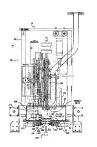
Initially retelling to FIGURES 1-8, 13 and 14, a filler apparatus 30 is
illustrated
for filling liquid or otherwise flowable food product into a flexible bag 400
under sterile
(aseptic) conditions. The bag 400 includes a fitment (also referred to as
"fitment
closure") 402, composed of a fitment or fill collar or neck 408 closed by a
cap 404. The
fill collar 408 is attached to the bag 400 at the end of the collar opposite
to the cap. The
collar may include flanges 410, 412, 414, extending around and outwardly of
the collar to
define circular grooves such as groove 406 that extends around the collar 408.
The bag
itself is composed of a tough, flexible, single- or multi-layer material such
as for
example, polyethylene, nylon, aluminum foil and rnetalized polyester. The bags
can be
of a wide range of sizes, from as small as three gallons and up to over 300
gallons, or
more and beyond. The collar 408 may be attached to the bag 400 by numerous
different
constructions as is known in the art The cap 404 can also be of various
constructions,
including having a top portion 416 that overlaps a cylindrical portion 418.
The
cy lindrical portion may be sized to closely fit within the inside and/or
outside of the neck
or collar 408.
Standard or common fitments are in use with flexible bags. The filler spouts
are
designed to accommodate such standard fitments. The present filler apparatus
can be
adapted to be used with nonstandard or unique fitments also.
The filler station or apparatus 30 in basic form includes a frame structure 50
that
defines a filler chamber 60, maintained in an overpressure condition by a
subtle gas, and
preferably by steam. A filler head assembly 100 is extendible downwardly and
retractable upwardly within the filler chamber. When extended downwardly, the
filler
head assembly 100 directs liquid food product to the flexible bag 400. During
the fill
process, the fill/fitment collar 408 is held stationary within a fitment
chamber 200,
located beneath the filler chamber 60 by a fitment holder assembly 350. The
apparatus 30 also includes a fitment top or cap removal and replacement
apparatus 450 to
remove the fitment cap 404 from the fitm.ent so that the bag can be filled,
and then to
replace the cap after the bag has been filled. Filler apparatus 30 in addition
includes a
CA 02911320 2015-10-30
WO 2014/189965
PCT/US2014/038835
plug assembly 300 for closing off the bottom of the filler chamber from the
fitment
chamber vvhen the filler head is not being used to fill the bag 400.
The filler apparatus 30 fitrther includes an actuatable fitment plug assembly
500
that may be placed against the bottom of the fitment collar to prevent steam
or other
gasses or liquids from the filler chamber to enter the bag 400 when
undesirable to do soõ
and also to maintain an overpressure condition in the filler chamber when the
cap 404 is
removed from the collar 408. Otherwise, when the cap 404 is removed from the
fitment
collar 408, the filler chamber would be placed in communication with the
entire volume
of the empty bag, thereby reducing the pressure in the filler chamber to an
unacceptable
level, which can result in contamination entering the fill chamber. If the
pressure is
maintained within the fill chamber, then contamination will be prevented from
entering
the fill chamber.
Now referring more specifically to the different aspects of the filler
apparatus 30,
the frame structure 50 of the filler apparatus is composed in part of a
plurality of upright
posts 52 spanning between a top plate structure 54 and a bottom plate
structure 56. The
frame structure 50 may be carried by a support structure, not shown. The
bottom plate
structure 56 forms the top of the filler chamber 60. The filler chamber 60 is
also formed
by yen:leaf side walls 62 and a floor plate structure 64 that engages the
lower edges of the
side walls 62. The filler chamber 60 is pressurized with a gas, preferably
steam, thereby
to prevent contaminants from entering the fill chamber and mixing with the
flowable food
product or from entering the container being filled, Thus, it is important to
maintain the
positive pressure within the fill chamber during the entire fill cycle.
Filler head assembly 100 is shown in FIGURES 1-4, 7 and 8, in upward retracted
position, and in FIGURES 5 and 6 in downward extended position. The filler
head
assembly 100 includes a leading head structure 102 defining an annular shaped
cavity 104, and a downwardly extending nipple or tip 106. A valve 108 is
positioned at
the intersection of the cavity 104 and nipple 106 to open and close the head
structure 102.
A product inflow tube 110 intersects the head structure 102 to deliver liquid
product into
the cavity 104. The tube 110 is connected to a source of food product, not
shown. The
filler head assembly 100 is extended and retracted by an appropriate
mechanism.
A central opening is formed in the floor plate structure 64 of the filler
chamber 60.
When desired, this opening is plugged or closed off by the plug assembly 300,
which is
shown in place in FIGURES 1, 2, and 8. In the remaining figures (FIGURES 3-7)
the
CA 02911320 2015-10-30
s
1Printed: 07/04/2015, DESCPAMD,
ili$2014038835
PCT/US 2014/038 835 - 23-03-2015
44758PCT
plug assembly 300 is removed from the floor plate structure and retracted away
to the left
side of the filler chamber.
The plug assembly 300 includes a plug structure 302 composed of a plug
body 304 that snuggly engages within the central opening formed in the floor
plate
structure 64. A seal 306 is seated within a groove extending around the floor
plate
structure opening to seal against the plug body 304. The plug structure 302
includes a
top 310 having a diameter somewhat larger than the diameter of the plug body
304, In
FIGURE 2, a portion of the plug structure 302 is broken away so that the
construction of
plug body 304 is visible: A bracket 312 connects the plug 'top to an actuator
assembly 314 that is moveable vertically and also rotatable about a vertical
axis 316. The
actuator assembly 314 is extendable downwardly to engage the plug assembly
into the
floor plate structure hole, and also to retract the plug assembly upwardly to
remove the
plug assembly from the floor plate structure hole and then rotate the plug
assembly away
from the central portion of the fill chamber to a position on the left side of
the fill
chamber 60, as shown in FIGURES 3-7. The actuator assembly 314 is mounted on
the
frame structure 50 by appropriate brackets or other mounting structure,
A fitment chamber 200 is positioned below the filler chamber 60. Enlarged
views
of the fitment chamber 200 are shown in FIGURES 13 and 14. The fitment chamber
200
is formed by the floor plate structure 64, as well as by a housing 202 that is
attached to
the underside of the floor plate structure, The housing 202 has a central
cavity 204 of
substantially the same diameter as the floor plate structure opening. A steam
inlet
line 206 and a steam outlet line 208 engage with passageways, not shown,
formed in the
housing 202 between the exterior perimeter of the housing and the central
cavity 204.
Control valves 210, 212, 214, and 216 control the flow of steam into and out
of the
cavity 204, as desired, for example, when sterilizing the fitment closure 402,
as described
below.
Referring to FIGURES 13 and 14, and also to FIGURES 19 and 20, a holder
assembly 350 is employed to hold the fitment closure 402 in place during
filling of the
bag 400. The fitment holder assembly 350 is mounted to the underside of the
fitment
chamber housing 202. The fitment holder assembly 350 includes a pair of slide
plates 352 that slide within spaced-apart parallel slideways 354 mounted to
the underside
of housing 202. The slideways 354 define longitudinal grooves 356 that closely
receive
the side edge portions of the slide plates 352, The center portions of the
slide plates 352
-8-
AMENDED SHEET
23/03/41.5j
CA 02911320 2015-10-30
'Printed: 07/04/201& IDE oP'AMD
lUS20140388351
PCT/US 2014/038 835 - 23-03-2015
44758PCT
=
cooperatively define a circular opening for receiving jaws 360 which is
positioned within
a shallow counter-bore formed in the slide plates. The jaws 360 are
constructed of two
halves, with a semi-circular central opening. As shown in FIGURES 13 and 14,
the
jaws 360 engage within a close-fitting groove 406 formed in the collar 408 of
fitment 402. The groove 406 is formed by spaced-apart flanges 410 and 412
extending
radially outwardly from the collar 408. The jaws 360 can be composed of any
suitable
material, for example, stainless steel or other metallic material, or other
types of material,
such as ceramic material.
An elastomenc seal 362 is located above jaw 360 to seal against the flange 412
that forms the upper side of the fitment groove in which the jaw 360 engages.
The
elastomeric seal 362 is backed by a backing ring 364 that overlies the jaws
360. The
seal 362 is semi-circular in shape so as to cooperatively form a complete
circular shape
when the slide plates 352 are engaged around fitment 402.
The positions of the slide plates 352 are controlled by linear actuators 370
which
may be powered by a gas, such as air, or a fluid, such as hydraulic fluid, in
a well known
manner. The actuators 370 are mounted to mounting brackets 372, which in turn
are
secured to the underside of floor plate structure 64, see FIGURES 13 and 19.
The
forward ends of linear actuators 370 extend through close-fitting openings
formed in the
mounting brackets 372, and are held in place by lock nuts 374 that engage with
threaded
collars extending forwardly from the forward end Of the actuator bodies. The
forward
ends of actuator rods 376 are connected to anchor brackets 378, which in turn
are secured
to the corresponding portions of slide plates 352. To this end, the forward
ends of the
actuator rods 376 may be threaded to engage threaded bores formed in the
brackets 378,
with the rods 376 held in place by lock nuts 380. It will be appreciated that
by the
foregoing construction, a very reliable and robust structure is provided for
the fitment
holder assembly 350.
Once the fitment closure 402 is in place in the fitment chamber and being held
by
the fitment holder assembly 350, prior to filling the bag 400 the fitment cap
404 is
removed. However, as discussed more fully below, before the fitment cap is
removed,
the fitment 402 is sterilized by steam introduced into the fitment chamber 200
through a
steam inlet line 206. During such sterilization of the fitment, the filler
chamber plug
assembly 300 is engaged in the fitment chamber opening formed in the floor
plate
structure 64, as shown in FIGURES 2 and 13,
-9-
AMENDED SHEET
23/03/20151
CA 02911320 2015-10-30
-
1Printed: 07/04/2015; DESCPAMD.
iUS2014038835j
PCT/US 2014/038 835 ¨ 23-03-2015
- 44758 ?CT
FIGURE 3 illustrates the fitment cap removal/replacement apparatus 450 as
engaged with the fitment cap 404. In FIGURE 3, the fitment cap 404 is being
removed
from the fitment collar 408. FIGURE 7 illustrates the fitment cap 404 being
replaced
over the fitment collar 408 after the bag 400 has been filled. FIGURES 15-18
show
additional views of the fitment cap removal and replacement apparatus 450.
The fitment cap removal/replacement apparatus 450 includes a pair of clamp
arms 452 that project from a pivot head 454, located at the lower end of a
pivot
cylinder 456. The ends of the pivot aims 452 at the pivot head 454 are secured
to the
lower ends of pivot rods 458 that extend downwardly through the pivot cylinder
456, that
extends downwardly from a frame structure 457, see FIGURE 17. Segment gears
460
and 462 are attached to the upper ends of the pivot rods 458. The segment
gears 460 and
462 mesh with each other, as shown in FIGURE 17. The segment gear 462 is
attached or
integrated into an end portion of a pivot arm 464 that projects outwardly from
pivot
cylinder 456. The distal end of the pivot arm 464 is connected to a linear
actuator 466 via
clevis 468 connected between the distal end of pivot arm 464 and a connecting
rod
extending from actuator 466. It will be appreciated that actuator 466 is
operated to
control the rotation of clamp arms 452 from an open or spread position, as
shown in
FIGURES 16 and 17, to a closed position as shown in FIGURE 18. An extension
spring 470 is connected between the distal end portions of clamp arms 452 to
bias the
clamp arms in closed position.
As most clearly shown in FIGURE 16, an attachment head 476 is mounted near
the distal end portions of the clamp arms 452. The attachment head 476
includes two
halves, that cooperatively define a generally cylindrical or circular shape.
The attachment
head 476 includes a generally cylindrical body portion 478 and an inwardly
extending
flange portion 480 at the lower edge portion of the body portion. The flange
portion 480
is sized to underlie the upper rim of the fitment cap, thereby to lift the cap
upwardly when
removing the cap from the fitment collar. In this regard, the pivot cylinder
456 of the
apparatus 450 is moveable vertically relative to frame 457 and also rotatably
about the
longitudinal axis of the pivot cylinder. This enables the apparatus to be
positioned so that
the attachment head 476 is positioned over the fitment cap 404 during the cap
removal
process. As the attachment head 476 is lowered, the clamp arms 452 are spread
until the
elevation of the attachment head is such that the flange portion 480 is
beneath the cover
flange of the fitment cap, whereupon the clamp arms are allowed to close over
the fitment
-10-
AMENDED SHEET
i'23/03/201781,
CA 02911320 2015-10-30
,
Printed: 07/04/2015, DESCPAMD
,US2014038835,
PCT/US 2014/038 835 ¨ 23-03-2015
. = 4475sper
=
cap. The attachment head is then raised upwardly via the upward movement of
the pivot
cylinder 456, and then the pivot cylinder itself is rotated so that the
fitment cap is moved
out of the vicinity of the fitment. After the flexible bag 400 has been
filled, the fitment
cap 404 is replaced by reversing the foregoing process. FIGURE 7 shows the
fitment
cap 404 replaced by the apparatus 450.
A fitment plug assembly 500 is provided to close off the bottom of the fitment
collar from the interior of the bag 400 at various portions of the filling
cycle for the
bag 400; for instance, when the fitment is being sterilized, when the fitment
cap is being
removed and before the fill process starts, and during the process of
replacing the fitment
cap after the bag has been filled.
The construction of the fitment plug assembly 500 is most clearly shown in
FIGURES 9-12. As shown in these Figures, the plug assembly 500 includes plug
502
mounted on the distal end portion of a pivot arm 504. The opposite end of the
pivot arm
is rotate* axled on cross pin 506 which spans between, and is held in place
by, two
spaced-apart mounting brackets 508 that are secured to the underside of the
fitment
chamber housing 202. A bushing 510 is interposed between the cross pin 506 and
a
close-fitting cross-bore extending through the pivot arm 504 so that the pivot
arm rotates
freely relative to the cross pin. . A portion of the pivot arm shown in FIGURE
10 is
broken away to illustrate this construction. The pivot arm 504 includes a
transverse
lug 512, shown extending downwardly from the pivot arm 504 in FIGURE 11. The
distal
end of an actuator rod 514 is connected to the lug 512 via a clevis 516
engaging through a
cross hole formed in the lug. The actuator rod 514 is part of linear actuator
518. The
opposite end of the linear actuator includes a pair of spaced-apart mounting
ears 520 that
are pinned to a bracket 522 depending downwardly from the floor plate
structure 64 of
the apparatus frame 50.
As shown in FIGURE 12, the plug 502 is constructed of a resilient Upper plug
layer 530 and a lower backing layer 532. The upper plug layer is constructed
of rubber,
synthetic rubber, a resilient plastic material or other durable but resilient
material that is
capable of sealing against the bottom of collar 408 to form a seal against the
collar. To
this end, the upper plug layer 530 is chamfered or radiused to provide a
relatively tight
seal against the lower end of collar 408. The backing layer 532 provides a
support for the
upper plug layer 530 on the pivot arm 504, which is substantially narrower
than the
diameter of the upper plug layer 530.
-11-
AMENDED SHEET
A
r?3/03/291A
CA 02911320 2015-10-30
WO 2014/189965
PCT/US2014/038835
The linear actuator 518 when extended pivots the plug 502 into position
against
the bottom of the fitment collar 408. Tri this manner, the plug remains
exterior of the
bag 400 and thus is not a source of possible contamination with the bag.
Moreover, the
portion of the bag interposed between the bottom of the collar 408 and the
plug 502 can
serve as a gasket or seal to positively close off the bottom of the collar
408.
When in such position, the plug assembly 500 is exterior of the bag 400, and
thus,
part of the bag is disposed between the upper surface of the plug 502 and the
bottom of
the fitment collar 408. When the actuator 518 is in contracted condition, the
plug 502 is
rotated away approximately 90 degrees from the fitment chamber 200 and the
associated
fitment 402, for example, as shown in FIGURES 1, 5, and 6. However, when the
plug
assembly 500 is in engaged position, the plug assembly closes off the bottom
of the
fitment collar from the interior of the bag itself. This is important when
removing the
fitment cap 404 from the fitment collar 408 in preparation to begin filling
the bag. By
closing off the bottom of the fitment collar with the plug 502, the pressure
within the
.. filler chamber 60 is maintained so as to retain the aseptic condition
within the pressurized
filler chamber. Proof of a positive pressure level in the filler chamber is a
regulatory
requirement in certain countries for aseptic filler systems. But for the
position of the
fitment plug 502 at the bottom of the fitment collar, when the fitment cap is
removed, the
steam or other moisture from the filler chamber would otherwise enter the
filler bag and
thereby drastically reduce the pressure within the filler chamber.
Also, after the bag has been filled and the filler head is being retracted and
the
fitment cap replaced, the fitment plug is again positioned against the lower
end of the
fitment collar to isolate or close off the fitment bag from the filler
chamber. Since a filled
bag, such as bag 400, is not filled to such an extent that there does not
remain an empty or
unfilled volume at the top of the bag, the engaged fitment plug 502 does not
place a
significant strain on the bag, even when filled. The positioning of the
fitment plug
against the lower end of the fitment collar not only helps maintain the
positive (over)
pressure within the filler chamber, but also prevents undesirable fluids from
entering the
= filler bag. Once the fitment cap has been replaced over the fitment
collar, the fitment
plug assembly can be retracted so that thereafter, the fitment can be released
by the
fitment holder assembly 350 and the bag removed from the filler apparatus, as
shown in
FIGURE 8.
-12-
CA 02911320 2015-10-30
WO 2014/189965 PCT/US2014/038835
The following will briefly describe a fill cycle utilizing the apparatus of
the
present disclosure. Chart A sets forth the positions of filler head assembly
100, filler
chamber plug assembly 300, fitment collar holder assembly 350, fitment cap
remover/retractor apparatus 450, and fitment plug assembly 500 during the fill
cycle.
CHART A
POSITION OF FILLER SYSTEM ELEMENTS DURING FILL CYCLE
. --------------------- , I
Fill Chamber I Filler Head Fitment Cap Fitment
'Fitment Phi g
Mu Assembly 100 Remover/ Collar Holder Assembly 500
Fill Cycle Figs tõ
- Assembly 300 Retractor 450 Assembly 350
1, Fill 1 In Place - , Retracted Retracted
Retracted Retracted
Chamber in Closing off Fill
Ready Chamber
Condition
¨ ---------- , --
2, Fill Bag 2 In Place ¨ Retracted Retracted Engaged with
In place
i in Place ¨ Closing off Fill Fitment
Collar i against
I Sterilizing Chamber
Fitment Collar ,
of Fitm eat :
Closure =
:
3. Fitment 3 Removed and Retracted Engaged with
Engaged with In place ,
Cap Retracted Fitment Cap
Fitment Collar against
Removal for Removal '
Fitment Collar
. ...
4. Fitment 4 Removed and , Retracted Retracted Engaged with
In place
Cap Retracted : Fitment
Collar against
Removed :
Fitment Collar
. f.- ............................................................ : .......
5. Filling of 5 & Removed and Engaged with
Retracted Engaged with : Retracted
Bag 6 Retracted Fitment Collar Fitment
Collar
________________________________________ `,.= ..... ,4, ....... ' .. - =
6. Bag 7 Removed and I Retracted Engaged with
Engaged with In place :
Filled, Retracted Fitment Cap Fitment
Collar against
Replace- : for piacement
Fitment Collar j
ment of .
= Fitment
Cap .
7, Fill 8 : In Place ¨ Retracted Retracted
Retracted Retracted !
Completed, Closing off Fill
Bag Chamber
Detached
from Fill
t ..........
System.
................................................ ..
Beginning at FIGURE 1, the filler apparatus 30 is shown in standby or ready
condition. In this regard, the bottom opening of the fill chamber is closed by
the fill
-13-
CA 02911320 2015-10-30
Printed: 07/04/2015. bE C PAWS,
,US2014038835,
PCT/US 2014/038 835 - 23-03-2015
= 44758PCT
chamber plug assembly 300 inserted into the center opening formed in the floor
plate
structure 64. The filler head assembly 100 is retracted in upward position.
Also, the
fitment plug assembly 500 is shown in retracted position, and thus swung away
from the
fitment chamber 200.
Next, as shown in FIGURE 2, the fitment 402 is held in place within the
fitment
chamber 200 by the fitment holder assembly 350. The fitment plug assembly 500
is in
engaged position so that the fitment plug 502 bears against the bottom of the
fitment
Collar 408. The top of the fitment chamber is still closed off by the fill
chamber plug
assembly 300, During this portion of the fill cycle, steam is introduced into
the fitment
chamber so as to sterilize the fitment 402.
After the sterilization of the fitment 402 has been completed, the fitment cap
404
is removed using the fitment cap removal/replacement assembly 450, FIGURE 3
shows
the removal/replacement assembly 450 engaged with the fitment cap 404. As
noted
above with respect to FIGURE 2, the fitment collar 408 is held tightly in
place by the
fitment holder assembly 350, and the plug 502 of the fitment plug assembly 500
is
engaged against the underside of the fitment collar 408. The operation of the
fitment cap
removal/replacement assembly has been described above.
Next in the fill cycle, FIGURE 4 shows the fitment cap 404 removed and the
fitment cap removal/replacement apparatus pivoted to temporarily position the
fitment
cap away from the fitment chamber 200. The plug 502 of the fitment plug
assembly 500
is retained tightly against the underside of the fitment collar, thereby
preventing loss of
pressure within the fill chamber and also preventing undesirable fluids from
entering the
bag 400. '
FIGURES 5, 6, and 14 illustrate the filling of the bag 400 with desired liquid
food
product. To this end, the filler head assembly 100 is extended downwardly so
that the
nipple 106 is disposed within the interior of the fitment collar 408. Food
products from
product inflow tube 110 can flow into and through the head structure 102 and
then
downwardly through the nipple 106, through the fitment collar 408, and into
the interior
of the bag 400. It will be appreciated that in this portion of the fill cycle
a fitment plug
assembly 500 is retracted so as to not obstruct the flow of the food product
through the
fitment collar.
Once the bag 400 has been filled, the filler head assembly 100 is retracted
upwardly to disengage the nipple 106 from the fitment collar, see FIGURE 7. At
this
-14-
AMENDED SHEET
le:
12370-3/2015
CA 02911320 2015-10-30
WO 2014/189965
PCT/US2014/038835
juncture, the fitment cap 404 is replaced by the fitment cap removal and
replacement
apparatus 450. The operation of the apparatus 450 is described above. During
this
portion of the fill cycle, the fitment plug assembly is in engaged position so
that the
plug 502 is against the underside of the fitment collar 408, thereby to
prevent loss of
pressure within the fitment chamber as well as prevent undesirable fluids from
entering
the bag 400 after the filler head assembly 100 has been retracted and before
the fitment
cap 404 has been placed back over the fitment collar.
Lastly, once the fitment cap 404 has been replaced, the fitinent 402 can be
released from the fitment holder assembly 350. Prior to such release, the
fitment plug
assembly 500 is retracted so as not to hinder the removal of the fitment from
the fitment
holder assembly 350. The filled bag 400 is removed from the filler apparatus
30, as
illustrated in FIGURE 8. It will be appreciated that steam can be introduced
into the
fitment chamber 200 after removal of the bag 400 to clean the fitment chamber
if
necessary.
The operation of the described fill cycle is controlled and sequenced by a
control
system that is capable of actuating the various systems and components of the
fill system
described above. The control system includes software that can be operated and
manipulated to adjust the fill system 30 and fill cycle to accommodate the
particular food
or other product being delivered to the filler bag 400, as well as the size
and other aspects
.. of the filler bag. Although not shown, a user interface may be provided
that can be used
to operate, manipulate and/or adjust the fill system 30 and fill cycle of the
present
disclosure.
While illustrative embodiments have been illustrated and described, it will be
appreciated that various changes can be made therein without departing from
the spirit
and scope of the invention. In this regard, although the till system and
process of the
present disclosure are specifically advantageous for use with low acid food
packaging,
the system and process can be used with aseptically filling flexible
containers with all
manner of fiowable food products. The fill system of the present disclosure
can also be
used with the aseptic filling of flexible containers with flowable products in
addition to
food products, for example, cosmetic products or medications.
-15-