Note: Descriptions are shown in the official language in which they were submitted.
CA 02911684 2015-11-06
DISPOSABLE DIAPHRAGM VALVE
BACKGROUND OF THE INVENTION
The present invention relates to disposable valves and more particularly to an
actuator
controlled diaphragm valve having a valve insert made out of a moldable
plastic having a fluid
chamber and a diaphragm component capable of controlled, repeatable and
accurate dispensing
of fluid materials of various types and viscosities and in various forms, such
as beads, dots and
the like.
Positive displacement rotary microvalves are known for dispensing fluid
materials such
as adhesives, epoxies, potting compounds, SMT adhesives, two-part adhesives,
silver and gold
filled adhesives, UV curable adhesives, and solder pastes in a repeatable and
accurate manner.
Typically, these dispensers for fluid material are used in a wide variety of
industries, such as
electronic assembly and repair, form in place gasketing, component assembly
and sealing,
mold-making, casting, tool and machine and equipment fabrication and assembly,
and a variety
of other uses.
Prior dispensing devices typically include a gear motor which controls the
rotation of a
feed screw supported in a housing. Fluid is fed to the housing from an
external pressure on the
fluid and to force the fluid material into the housing. Supported in the
housing for rotation by
the motor is a feed screw or auger which urges the fluid material into a
dispensing tip which is
affixed to the output end of the housing. The dispensing tip is essentially in
the form of a
pointless needle which is locked and sealed to the output end of the housing.
The valve includes a rotary screw of a variable pitch type which homogenizes
low
viscosity material and which compresses the material to reduce its volume. A
one piece
housing having a sleeve located in the bore and which extends only partly up
the bore area.
The housing also includes a passageway formed in the housing through which the
fluid flows
and which is in contact with the passage wall as the fluid is urged into the
bore. The portion of
-1-
CA 02911684 2015-11-06
the bore above the sleeve may be contacted with the fluid since there is no
seal between the
upper portion of the bore and the sleeve. The housing also includes a screw
which holds a
dispensing coupling and thus the sleeve and the bore, a gasket being provided
between the
dispensing coupling and the lower portion of the sleeve.
Although prior microvalve dispensers operate satisfactorily, there are
circumstances
which require improvements which can be made. For example, dispensers are
normally used
continuously in assembly line and commercial operations except during lunch
breaks and after
a shift is over. If the material being dispensed hardens in the microvalve or
degrades for any
reason, then the valve has to be cleaned out and this is a difficult
operation. Should such
.. hardening occur, the unit is often sent back to the supplier for cleaning
and thus may be
expensive and create considerable down time. In addition, materials being
dispensed may
change during operation and it may be the case that later dispensed material
is contaminated by
that previously dispensed or is incompatible with the previously dispensed
material. In such a
case, the contamination must be cleaned out of the valve, which also can lead
to considerable
.. expense and down time for cleaning.
Consequently, improvements to address these issues were developed such that
all
interior surfaces that come into contact with fluid being dispensed were
readily replaceable
therefore reducing costs of cleaning and repair and reducing down time in
assembly and
commercial operations. Such microvalve devices included a conventional gear
driven motor
unit to which was mounted a housing for the valve. Supported within the
housing was a
disposable insert chamber which forms the interior wet surfaces of the
dispenser. The insert
includes a feed arm through which fluid under pressure from an external source
is fed to the
interior of the insert and thus the fluid does not contact the feed arm
surfaces of the housing of
the microvalve. Located in the insert is a feed mechanism connected to and
driven by the
motor, to dispense a measured amount of fluid accurately and controlled by the
motor. Such
prior disposable inserts required a motor having and output shaft for driving
a helical screw or
-2-
auger supported for rotation in the insert. Fluid in a measured amount,
depending on the
rotational speed and configuration of the screw was urged out of the outlet
which forms the exit
passageway for the insert. Although such disposable rotary microvalve insert
configuration
works well, having to include a helical screw or auger supported for rotation
within the insert is
a complicated mechanism adding to the complexity and expense of the insert
which is
disposable. Consequently a need exists for a simplified disposable valve
insert which is less
expensive to manufacture yet provides consistent and reliable performance.
SUMMARY OF THE INVENTION
The present invention is directed to a disposable actuator controlled
diaphragm valve
insert which addresses the drawbacks of prior disposable insert designs. The
present invention
provides a relatively simple microvalve structure in which all of the interior
surfaces which
come into contact with the fluid being dispensed are readily replaceable
therefore reducing cost
of cleaning and repair in reducing down time in assembly in commercial
operation.
Accordingly, there is described a valve assembly for dispensing fluid as a
bead or a dot
comprising: a housing having an internal cavity; a reciprocating actuator; and
a disposable
replaceable insert positioned within the cavity of the housing having interior
surfaces which
come into contact with the dispensing fluid, a fluid inlet, a fluid chamber
and a fluid outlet,
wherein the disposable replaceable insert further has a diaphragm adjacent the
fluid chamber
between the fluid inlet and the fluid outlet which when engaged by the
reciprocating actuator
opens and closes a fluid path in the fluid chamber between the fluid inlet and
the fluid outlet for
dispensing the fluid, and the disposable replaceable insert, as an assembled
unit, being readily
replaceable with a different disposable replaceable insert, as an assembled
unit.
The valve assembly operates to dispense fluids such as adhesives, epoxies,
solder paste,
etc. as a dot or bead. The replaceable insert is made out of a moldable or
machinable plastic
- 3 -
CA 2911684 2018-05-16
compound and includes both a fluid chamber and a diaphragm component which are
joined and
sealed together by either ultra-sonic, laser or spin welding processes or they
can be glued or
snap-fitted together. The insert may have fluid inlet and outlet passages
which extend beyond
the valve body. Attached to the outlet passage is a removable and replaceable
dispensing tip.
When the insert is installed into the valve body, the diaphragm head is
engaged with an
actuator. When the actuator is reciprocating, the diaphragm will move in the
same motion and
thus fluid will be dispensed.
A latching feature may be provided on the diaphragm component with a screw,
rod or
other material insert for added strength. The diaphragm component can be made
with additives
in the base moldable plastic to change the strength and compliance of the
diaphragm
component. Additionally, the fluid chamber component is made of a material
which facilitates
the joining of the fluid chamber and diaphragm components.
There is also described a disposable diaphragm valve insert for a housing of a
fluid
dispensing assembly comprising: interior surfaces which come into contact with
a dispensing
fluid; a fluid inlet; a fluid chamber for receipt of fluid from the fluid
inlet; a fluid outlet for
exiting of fluid out of the fluid chamber; a flexible diaphragm positioned
above the fluid
chamber for opening and closing a fluid path between the fluid inlet and the
fluid outlet; and a
latching feature adjacent the diaphragm opposite the fluid chamber, wherein
the disposable
diaphragm valve insert, as an assembled unit, is readily replaceable with a
different disposable
diaphragm valve insert, as an assembled unit.
In a further aspect, there is described a method of dispensing fluid in a bead
or a dot
through a fluid dispensing valve assembly comprising a housing having a
disposable diaphragm
valve insert with interior surfaces which come into contact with a dispensing
fluid, comprising
the steps of: positioning the disposable diaphragm valve insert into an
internal cavity of the
housing; introducing fluid into a fluid chamber in the disposable diaphragm
valve insert;
- 4 -
CA 2911684 2018-05-16
reciprocating an actuator to engage and disengage a diaphragm within the
disposable
diaphragm valve insert to move the diaphragm through the fluid chamber;
dispensing the fluid
when the actuator is disengaged with the diaphragm; and replacing the
disposable diaphragm
valve insert, as an assembled unit, with a different disposable diaphragm
valve insert, as an
assembled unit.
These and other aspects and advantages of the present invention will become
apparent
with the following specification, which, together with the accompanying
drawings describes
and illustrates embodiments of the invention.
BRIEF DESCRIPTION OF THE DRAWINGS
FIG. 1 is an exploded perspective view of the microvalve dispenser of the
present
invention;
FIG. 2 is a bottom view of the dispenser of FIG. 1;
FIG. 3 is a side view of the disposable valve insert of FIG. 1; and
FIG. 4 is a side view of the dispenser of FIG. 1 illustrated in partial
section.
DETAILED DESCRIPTION OF THE INVENTION
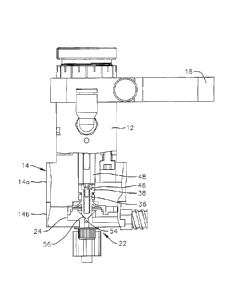
As shown in FIGS. 1 through 3, a microvalve dispenser assembly 10 is
illustrated. The
assembly includes an actuator 12 having a housing 14 mounted thereon. A
mounting bracket 16
is supported by the actuator for mounting various dispensed material sources.
The actuator
may be any one of either a pneumatic or hydraulic driven type or direct
current servo or stepper
motor type. The actuator may be controlled by a controller mechanism (not
shown).
- 4a -
CA 2911684 2018-05-16
CA 02911684 2015-11-06
The housing 14, which may be of metal such as aluminum, or a corrosion
resistant
plastic such as acetal, for example, may be made up of a main body housing 14a
and a body
front plate 14b held together by captive screws 18. The main body housing 14a
and the front
body plate 14b cooperate to form an internal cavity 20 for receipt of a
disposable diaphragm
.. valve insert 22. The insert 22 includes a fluid chamber component 24 and a
diaphragm
component 26. The fluid chamber and the diaphragm components include a joint
28 for joining
and sealing the components together by either an ultra-sonic, laser or spin
welding process or
are snap-fitted or glued together. The valve insert is preferably made out of
a moldable or
machinable plastic compound. The insert includes a fluid inlet passage 30 and
a fluid outlet
passage 32. The outlet passage 32 has a removable and replaceable dispensing
tip 34. The
diaphragm component 26 includes a latching feature 36 having an enlarged head
portion 38.
The fluid inlet passage 30 includes an outer circumferential shoulder 40 which
extends
beyond the housing and body front plate 14b thus preventing rotational
movement of the insert
relative to the housing. The outer surface is threaded 42 so that a fluid
supply source may be
.. easily attached and removed. Similarly the fluid outlet passage 32 has a
shoulder portion 44
which extends beyond a lower surface of the body front plate 14b. Shoulder 44
assists in
attaching the dispensing tip securely.
As seen best in FIG. 4, when the disposable diaphragm valve insert 22 is
positioned
within the cavity 20 of the housing 14 the head portion 38 of the latching
feature 36 is engaged
with a chuck 48 which is driven by the actuator 12. The latching feature 36
can include an
additional strength feature such as a screw 46 which could also be a rod or
other material insert.
The sealing feature 56 of the diaphragm component 26 is positioned between the
latching
mechanism and the fluid chamber component 24 such that when the chuck 48 is
reciprocating
the diaphragm moves in the same motion to dispense a fluid. The fluid is
dispensed by the
diaphragm opening and closing the fluid path 54 as fluid is being pumped in
the inlet under
pressure. The diaphragm can be made with or without additives in the base
moldable or
-5-
CA 02911684 2015-11-06
machinable plastic material to change the strength and compliance of the
diaphragm as needed
based upon the fluid being dispensed. The diaphragm 26 and the feed chamber 24
can be made
of various materials such that the feed chamber and the diaphragm can be
joined and sealed
together. Additives to either the base moldable plastic material or the
diaphragm can be
fiberglass, glass beads, carbon fiber or elasticizers
Although the present invention has been described and illustrated with respect
to
various embodiments thereof, it is to be understood that changes and
modifications can be
made herein which are within the full intended scope of the invention as
hereinafter claimed.
-6-