Note: Descriptions are shown in the official language in which they were submitted.
CA 02911841 2015-09-15
WO 2013/148522
PCT/US2013/033550
LASERGRAMMETRY SYSTEM AND METHODS
CROSS REFERENCE TO RELATED APPLICATIONS
The present application claims the benefit of U.S. Provisional Patent
Application No.
61/615,249, filed March 24, 2012, the entire contents of which are
incorporated herein by
reference.
FIELD OF DISCLOSURE
This invention relates to a system and methods for 3-dimensional measurement
of the surface
and/or features of an object.
BACKGROUND
Many of today's advanced production processes require in-line quality control
and in-process
verification. This is especially important, for example, in aircraft
manufacturing, where most
of assembly operations are manual. Human errors are unacceptable and they have
to be
revealed immediately making sure they do not propagate into further production
steps. One
hundred percent quality assurance is often needed. Hence, in-process
measurement of 3-
dimensional structures, parts, and assemblies is frequently required. In a
number of situations,
especially involving composites, the only acceptable ways of 3D measurement
are those
employing non-contact methods, for example, lasergrammetry. Lasergrammetry is
a non-
contact measurement technology in which the 3D coordinates of points on an
object are
determined by utilizing laser pointing and scanning methods.
On the other hand, laser systems known as laser projectors are already widely
used in
contemporary manufacturing. Laser scanning technique in the form of laser
projection is
often utilized in production processes as a templating method in manufacturing
of composite
parts, in aircraft and marine industries or other large machinery assembly
processes, truss
building, painting, and other applications. It gives the user ability to
eliminate expensive hard
tools, jigs, templates, and fixtures. Laser projectors utilize computer-
assisted design (CAD)
data to generate glowing templates on a 3D object surface. Glowing templates
generated by
laser projection are used in production assembly processes to assist in the
precise positioning
of parts, components, and the like on any flat or curvilinear surfaces. Laser
projection
technology brings flexibility and full CAD compatibility into the assembly
process. In the
laser assisted assembly operation, a user positions component parts by
aligning some features
(edges, comers, etc.) of a part with the glowing template. After the part
positioning is
1
CA 02911841 2015-09-15
WO 2013/148522
PCT/US2013/033550
completed, the user fixes the part with respect to the article being
assembled. However, the
accuracy of laser projection, and, consequently, of the assembly process, is
only adequate if
the object is built exactly up to its CAD model. This is not the case for all
applications, and as
such there arc a number of non-trivial issues associated with such
applications.
SUMMARY
In view of the above, the Applicants have realized that there are many
applications where
different manufacturing operations assisted by laser projection needed to be
combined with
in-process non-contact methods of 3D measurement including surface digitizing,
feature
detection, etc. Hence, there is a need for a combined laser projection and
lasergrammetry
system and methods.
In one aspect a lasergrammetry system, including: an aiming laser projector
configured to
direct a focused laser beam toward a designated point on a surface of an
object thus
producing a stationary laser light spot on the surface; and a sensing laser
projector configured
to scan, detect, and locate the laser light spot created by the aiming laser
projector. In some
embodiments, the aiming and sensing laser projectors are associated with
aiming and sensing
optical paths, respectively. Some embodiments include a computer configured to
calculate
3D coordinates of the designated point using ray direction vectors associated
with the aiming
and sensing optical paths.
In some embodiments, a fixed set of fiducials are provided on the object, and
both the aiming
and the sensing laser projectors are further configured to obtain optical
feedback signals from
the fiducials and to define the location and orientation of the aiming and
sensing projectors in
3D space with respect to a coordinate system of the object.
In some embodiments, the aiming laser projector includes a laser, a focusable
beam expander,
a beam steering system, a controller, and an optical feedback subsystem
capable of detecting
a portion of laser light reflected from a fiducial on the object.
2
CA 02911841 2015-09-15
WO 2013/148522
PCT/US2013/033550
In some embodiments, the optical feedback subsystem includes a photodetector
configured to
receive said portion of the reflected laser light and convert it into an
electrical image signal
that corresponds to the intensity of the detected feedback light.
In some embodiments, the sensing laser projector includes a laser, a focusable
beam
expander, a beam steering system, a controller, and an optical feedback
subsystem capable of
detecting a portion of laser light reflected from a fiducial on the object.
In some embodiments, the optical feedback subsystem includes a high
sensitivity
photodetector that is configured to detect said portion of the reflected laser
light, and to detect
a portion of the aiming projector's light reflected from the object surface.
In some embodiments, the optical feedback subsystem further includes an
imaging lens
having an optical axis and an aperture mask in front of the high sensitivity
photodetector.
In some embodiments, the aperture mask is translatable together with the
photodetector along
the optical axis of the imaging lens.
In some embodiments, the sensing laser projector is configured to allow object
feature
detection.
In some embodiments, a set of fiducials are provided on the object, and the
fiducials are
inherent to the object.
In some embodiments, each of the aiming and sensing laser projectors is
capable of
functioning as the aiming laser projector or as the sensing laser projector.
In some embodiments, the system is configured for reverse engineering
applications and to
provide 3D coordinate measurements a group of points utilizing a bundle
solution.
Some embodiments include a free located scale rod with at least two fiducials.
3
CA 02911841 2015-09-15
WO 2013/148522
PCT/US2013/033550
Some embodiments include at least one auxiliary video camera configured to
image at least a
portion of the object, where the system is configured to use a signal from the
video camera to
at least partially control the operation of the sensing projector.
In some embodiments, the video camera is configured to obtain one or more
images of the
laser light spot on the surface, and the system is configured to control the
sensing projector to
sense a limited area of the surface corresponding to the laser light spot
based at least in part
on the one or more images.
In another aspect, a lasergrammetry method is disclosed including: using an
aiming laser
projector to direct a focused laser beam toward a designated point on a
surface of an object
thus producing a stationary laser light spot on the surface; and using a
sensing laser projector
to scan, detect, and locate the laser light spot created by the aiming laser
projector. In some
embodiments, the aiming and sensing laser projectors are associated with
aiming and sensing
optical paths, respectively. Some embodiments include calculating 3D
coordinates of the
designated point using ray direction vectors associated with the aiming and
sensing optical
paths. In some embodiments, calculating step is carried out using at least one
computer.
Some embodiments include providing a fixed set of fiducials on the object, and
using the
aiming and the sensing laser projectors to obtain optical feedback signals
from the fiducials
and to define the location and orientation of the aiming and sensing
projectors in 3D space
with respect to a coordinate system of the object.
In some embodiments, the aiming laser projector includes a laser, a focusable
beam expander,
a beam steering system, a controller, and an optical feedback subsystem. Some
embodiments
include using the optical feedback system to detect a portion of laser light
reflected from a
fiducial on the object.
In some embodiments, the optical feedback subsystem includes a photodetector.
Some
embodiments inlclude using the photodetector to receive said portion of the
reflected laser
light and convert it into an electrical image signal that corresponds to the
intensity of the
detected feedback light.
4
CA 02911841 2015-09-15
WO 2013/148522
PCT/US2013/033550
In some embodiments, the sensing laser projector includes a laser, a focusable
beam
expander, a beam steering system, a controller, and an optical feedback
subsystem. Some
embodiments inlcude using the optical feedback subsystem to detect a portion
of laser light
reflected from a fiducial on the object.
In some embodiments, the optical feedback subsystem includes a high
sensitivity
photodetector. Some embodiments include using the photodetector to detect said
portion of
the reflected laser light, and to detect a portion of the aiming projector's
light reflected from
the object surface.
In some embodiments, the optical feedback subsystem further includes an
imaging lens
having an optical axis and an aperture mask in front of the high sensitivity
photodetector.
Some embodiments include translating the aperture mask together with the
photodetector
along the optical axis of the imaging lens.
Some embodiments include detecting one or more features using the sensing
laser projector.
In some embodiments, the object includes one or more inherent fiducials.
In some embodiments, each of the aiming and sensing laser projectors is
capable of
functioning as the aiming laser projector or as the sensing laser projector.
Some embodiments include implementing one or more reverse engineering
applications; and
providing 3D coordinate measurements a group of points utilizing a bundle
solution.
Some embodiments include obtaining a video image of at least a portion of the
object, and
using a signal from the video camera to at least partially control the
operation of the sensing
projector.
Some embodiments include obtaining one or more images of the laser light spot
on the
surface, and controlling the sensing projector to sense a limited area of the
surface
corresponding to the laser light spot based at least in part on the one or
more images.
5
CA 02911841 2015-09-15
WO 2013/148522
PCT/US2013/033550
In some embodiments, the object includes a set of fiducials, and the method
includes: using
the aiming projector and the fiducials to determine the location and
orientation of the
projector in 3D space with respect to the object's coordinate system based at
least in part on
coordinate data for the fiducials with respect to the coordinate system; using
the sensing
projector and the fiducials to determine the location and orientation of the
projector in 3D
space with respect to the object's coordinate system based at least in part on
coordinate data
for the fiducials with respect to the coordinate system; and performing a
sequential point-by-
point measurement of a surface of the object to obtains a series of digitized
3D coordinates of
the surface. Some embodiments include comparing the series of digitized 3D
coordinates of
the surface to a model of the surface. Some embodiments include generating an
output
indicative of differences between the digitized 3D coordinates and the model.
In some embodiments, the object includes a set of fiducials, and the method
includes: using
the aiming projector and the fiducials to determine the location and
orientation of the
projector in 3D space with respect to the object's coordinate system based at
least in part on
coordinate data for the fiducials with respect to the coordinate system; using
the sensing
projector and the fiducials to determine the location and orientation of the
projector in 3D
space with respect to the object's coordinate system based at least in part on
coordinate data
for the fiducials with respect to the coordinate system; using the aiming and
sensing
projectors, to measure 3D coordinates of at least three points in the vicinity
of a feature on
the object having an edge; generating a model of the surface of the object in
the vicinity of
the feature based on the 3D coordinates; using the sensing projector to detect
the edge of the
feature; and determining 3D coordinates for one or more points associated with
the edge.
Some embodiments include determining beam steering angles associated with a
plurality of
points corresponding to the detected edge; determining a plurality of sensing
rays based on
the beam steering angles; and determining points where the sensing rays would
intersect the
surface based on the model of the surface. In some embodiments, the model
includes a planar
fit to the surface. In some embodiments, feature includes a hole. Some
embodiments include
performing process verification based on measurements of the object.
Some embodiments include providing a free located scale rod with at least two
fiducials in
the vicinity of the object. Some embodiments include scanning fiducials of the
scale rod with
the aiming projector and, the sensing projector; determining beam steering
angles associated
with the fiducials for both the aiming projector and the sensing projector;
assigning object
6
CA 02911841 2015-09-15
WO 2013/148522
PCT/US2013/033550
surface points for measurement, using the aiming laser projector, projecting
stationary laser
spots onto the surface of the object at desired points; using the sensing
laser projector to scan
the spots to determining the beam steering angles corresponding to the center
of each spot for
both the aiming projector and the sensing projector. In some embodiments, the
step of using
the sensing laser projector to scan the spots is performed while sensing
projector is not
projecting a laser beam. Some embodiments include performing a bundle solving
calculation
based on an entire set of beam steering angles for all the measurement points
and the scale
bar fiducials to generate 3D coordinates of all the measurement points.
In another aspect, a non-transitory computer readable media including a set of
instructions
that, when executed, case a lasergrammetry system to implement the method of
any of the
types descried above.
Various embodiments may include any of the above described elements, alone or
in any
suitable combination.
BRIEF DESCRIPTION OF THE DRAWINGS
Fig. 1 is a diagram of a lasergrammetry system configured in accordance with
an
embodiment of the present invention.
Fig. 2 is a block diagram of an example aiming laser projector that can be
used in the system
of Fig. 1, in accordance with an embodiment of the present invention.
Fig. 3 is a perspective view of an example galvanometer based beam steering
system that can
be used in the aiming laser projector of Fig. 2, in accordance with an
embodiment of the
present invention.
Fig. 4 is a block diagram of an example sensing laser projector that can be
used in the system
of Fig. 1, in accordance with an embodiment of the present invention.
Fig. 5 is a diagram illustrating relation between components of the example
optical feedback
subsystem of the sensing laser projector of Fig. 4 and the object surface with
the laser spot, in
accordance with an embodiment of the present invention.
Fig. 6 is a detailed plan view of an example aperture mask that can be used in
the sensing
laser projector of Fig. 4, in accordance with an embodiment of the present
invention.
7
CA 02911841 2015-09-15
WO 2013/148522
PCT/US2013/033550
Fig. 7 is a diagram of a lasergrammetry system configured in accordance with
another
embodiment of the present invention.
Fig. 8 is a diagram of a lasergrammetry system configured in accordance with
yet another
embodiment of the present invention.
Fig. 9 is an illustration with details related to a first example
lasergrammetry method
according to an embodiment of the present invention.
Fig. 10 is an illustration with details related to a second example
lasergrammetry method
according to another embodiment of the present invention.
Fig. 11 is a diagram of a lasergrammetry system configured with an auxiliary
video camera in
accordance with another embodiment of the present invention.
DETAILED DESCRIPTION
Lasergrammetry techniques are disclosed. In one example embodiment, a
lasergrammetry
system is provided, the system including an aiming laser projector and a
sensing laser
projector. The aiming laser projector is configured to direct a focused laser
beam toward a
designated point on a surface of an object thus producing a stationary laser
light spot on the
surface. The sensing laser projector is configured to scan, detect, and locate
the laser light
spot created by the aiming laser projector. The aiming and sensing laser
projectors are
associated with aiming and sensing optical paths, respectively. The system may
further
include a computer configured to calculate 3D coordinates of the designated
point using ray
direction vectors associated with the aiming and sensing optical paths. The
sensing and
aiming laser projectors may be interchangeable allowing for dual functionality
and/or
configured to allow object feature detection. Numerous applications,
methodologies, and
system architectures will be apparent in light of this disclosure.
General Overview
As previously explained, there are a number of non-trivial issues associated
with laser
assisted assembly operations, particularly given that the accuracy of laser
projection, and,
consequently, of the assembly process, is only adequate if the object is built
exactly up to its
CAD model, which is not always the case. For example, "as-build" thickness or
shape of a
large composite part may become different from "as-designed" during the lay-up
process. In
8
CA 02911841 2015-09-15
WO 2013/148522
PCT/US2013/033550
such situations, in-process 3D digitizing of the object surface can be used to
facilitate
accurate lay-up and assembly assisted by laser projection. Also, because the
manual assembly
process relies on the visual judgment of a worker, in-process verification is
often required to
double check an article placement. This is especially true for some industries
with very strict
production requirements like, for example, aircraft manufacturing. For such
reasons, there are
many applications where different manufacturing operations assisted by laser
projection can
be combined with in-process non-contact methods of 3D measurement including
surface
digitizing, feature detection, etc.
Thus, and in accordance with an embodiment of the present invention, a
combined laser
projection and lasergrammetry system is provided, along with various
associated techniques.
One specific example embodiment provides a lasergrammetry solution that is
based on using
at least two laser projectors. As will be appreciated in light of this
disclosure, the main
technique provided in accordance with such an embodiment can generally be
referred to as
probing an object surface with a laser spot. In accordance with one such
embodiment, a first
laser projector is designated for aiming and a second laser projector is
designated for sensing.
The "aiming" laser projector directs a focused laser beam toward a designated
point on the
object surface thus producing a stationary laser spot on the surface. The
"sensing" laser
projector scans, detects, and locates the laser light spot created by the
"aiming" laser
projector. The system can then calculate the 3D coordinates of the designated
point using ray
direction vectors associated with the aiming and sensing optical paths, in
accordance with
some such embodiments.
In one specific such embodiment, the lasergrammetry system for 3D measurement
and in-
process verification comprises the aiming and sensing laser projectors, a
computer, and a
fixed set of fiducials, for example, retro-reflective targets. The 3D
coordinates of the fiducials
are presumed to be known with respect to the object's coordinate system. Both
the aiming and
the sensing laser projectors have ability to obtain optical feedback signals
from the fiducials
and to define the location and orientation of the projectors in 3D space with
respect to the
object's coordinate system.
Continuing with the specific embodiment, the aiming projector includes a
laser, a focusable
beam a beam steering system, a controller, and an optical feedback subsystem
capable of
detecting a portion of the aiming projector's laser light reflected from a
fiducial. The optical
feedback subsystem of the aiming projector includes a photodetector that
receives said
portion of the reflected light and converts it into an electrical image signal
that corresponds to
9
CA 02911841 2015-09-15
WO 2013/148522
PCT/US2013/033550
the intensity of the detected feedback light. During the process of defining
the aiming
projector's location and orientation in 3D space with respect to the object's
coordinate system
(this defining is generally termed as "bucking-in") this projector
sequentially scans fiducials
with its focused laser light spot. Fiducial scanning is performed by the
projector's
In accordance with some such specific embodiments, the sensing projector also
includes a
laser, a focusable beam expander, a beam steering system, a controller, and an
optical
feedback subsystem. The sensing projector can define its location and
orientation in 3D space
with respect to the object's coordinate system, e.g. buck-in, in the same
manner as previously
described for the aiming projector. However, the optical feedback subsystem of
the sensing
projector includes a high sensitivity photodetector that is capable of
detecting not only a
portion of the sensing projector's own laser light reflected from a fiducial
during bucking-in,
but also capable of detecting a portion of the aiming projector's light
reflected from the object
surface area where the aiming projector directs its laser beam during the 3D
measurement of
an object surface point coordinates.
In accordance with some embodiments of the present invention, the optical
feedback
subsystem of the sensing laser projector includes an imaging lens and an
aperture mask in
front of the high sensitivity photodetector. The aperture mask is translatable
together with the
photodetector along the optical axis of the imaging lens. In the process of
the object surface
point measurement, the aiming projector uses its beam steering system to
direct a focused
laser beam toward the designated measurement point and the sensing projector
uses its beam
steering system to scan the area of the aimed laser light spot. The aperture
mask serves as an
image analyzer. The light passing through the aperture mask is captured by the
high
sensitivity photodetector. The last one converts the light into an electrical
image signal. The
signal is processed by the sensing projector's controller utilizing an image
processing
algorithm that computes a direction vector of the sensing optical path toward
the center of the
laser light spot. Consequently, the system's computer calculates the X, Y, Z
coordinates of the
measurement point utilizing the aiming ray direction vector data from the
aiming projector
and the sensing ray direction vector data from the sensing projector. Note
that before the
measurement scan, the aperture mask is placed into the image plane conjugate
with the object
surface area to be scanned. This technique substantially improves measurement
precision by
reducing the impact of laser light speckles, in accordance with some
embodiments.
In another example embodiment, the sensing laser projector is enhanced to
enable the object
feature detection in accordance with the solution described in details in U.S.
Patent No.
CA 02911841 2015-09-15
WO 2013/148522
PCT/US2013/033550
7,306,339, the entire disclosure of which is incorporated herein by reference
at Appendix A.
In this becomes a part of the background and stray light suppressing system.
Utilizing the
sensing projector with object feature detection capabilities allows advanced
types of 3D
measurement and in-process verification, for example, to combine edge
detection with
surface or plane fitting through the designated measurement points.
In still another embodiment configured with two lasers, each of the laser
projectors is capable
of functioning as the aiming laser projector or as the sensing laser
projector, and both can be
enhanced to enable the object feature detection capabilities, in some such
embodiments. This
example embodiment offers a number of advantages. First of all, the system
fiducials can be
any type of features, such as holes, fasteners, dots, corners, or retro-
reflective targets, for
example. Second, as with the previous embodiment, such a system can perform
advanced
types of 3D measurement and in-process verification. Moreover, such a
symmetrical system
can achieve better accuracy by averaging the measurements performed, first,
when one laser
projector is aiming and the other is sensing and then, second, interchanging
them so that the
aiming projector becomes the sensing projector and the sensing projector
becomes the aiming
projector.
In another embodiment, a lasergrammetry system is provided that does not
include a fixed set
of fiducials with known coordinates. Instead, it includes just a free located
scale rod with at
least two fiducials. The distance between fiducials is presumed to be known.
In accordance
with this example embodiment of the present invention, such a system can be
used for,
instance, for general reverse engineering applications and it provides 3D
coordinate
measurements of a group of points utilizing a bundle solution method similar
to conventional
photo grammetry methods.
Numerous lasergrammetry methods for 3D coordinate measurements and in-process
verification will be apparent in light of this disclosure.
For instance, a first example method is a lasergrammetry method for 3D
digitizing of the
surface of an object that relies on using at least two laser projectors - the
aiming laser
projector and the sensing laser projector. Some such embodiments can be based
on utilizing a
fixed set of fiducials. The 3D coordinates of the fiducials are presumed to be
known with
respect to the object's coordinate system. In accordance with one such
specific example
embodiment,
11
CA 02911841 2015-09-15
WO 2013/148522
PCT/US2013/033550
- Bucking-in the aiming laser projector and the sensing laser projector
into the object
coordinate system using the given set of fiducials.
- If the CAD model of the surface is known, selecting the desired surface
point for
measurement by its nominal coordinates, and then calculating the beam steering
angles and projecting the stationary laser spot with the aiming projector onto
the
surface at the selected point. If the CAD model of the surface is not known,
assigning
the surface point for measurement by projecting the stationary laser spot with
the
aiming projector onto the unknown surface at a desired point.
- Determining the aiming ray direction vector.
- If the CAD model of the surface is known, calculating the beam steering
angles for
the sensing projector corresponding to the selected measurement point, then
focusing
the sensing projector aperture mask, and then scanning a predetermined small
area
that surrounds the aimed spot with the sensing projector while its own laser
beam is
turned off. If the CAD model of the surface is not known, producing a large
search
scan by the sensing projector first, detecting the location of the aimed spot,
then
calculating the beam steering angles for the sensing projector corresponding
to the
detected spot location, then focusing the sensing projector aperture mask, and
then
scanning a predetermined small area that surrounds the aimed spot with the
sensing
projector while its own laser beam is turned off
-Processing the signal obtained from scanning of the predetermined small area
that
surrounds the aimed spot and determining the sensing ray direction vector
corresponding to the center of the aimed spot.
- Calculating 3D coordinates of the measurement point with respect to the
object
coordinate system using the obtained aiming and sensing rays.
- Repeating the above steps for a plurality of measurement points to generate
a series
of digitized 3D coordinates of the surface. Note that the use of the term
'steps' as used
herein is not intended to imply a rigid or otherwise fixed order, and other
embodiments may have the various steps performed in different sequence.
- If the CAD model of the surface is known, perform verification by
comparing the
measurement results with the model.
12
CA 02911841 2015-09-15
WO 2013/148522
PCT/US2013/033550
A second example method is a lasergrammetry method for advanced 3D measurement
and in-
process verification. This example embodiment combines 3D digitizing of the
surface of an
object with an edge detection technique and allows for measurement of a
location of a given
object edge in 3D space. Therefore, such embodiment provides a greater degree
of flexibility
and versatility relative to the first example. As will be appreciated, this
method uses at least
two laser projectors - the aiming laser projector and the sensing laser
projector. At least one
projector, which in some such embodiments is the sensing projector, is
implemented with a
laser projector configured with object feature detection capabilities. As will
be further
appreciated, such methodology can be based, for example, on utilizing a fixed
set of fiducials.
The 3D coordinates of the fiducials are presumed to be known with respect to
the object's
coordinate system. In accordance with one such specific example embodiment,
the method
includes the following:
- Selecting or assigning a set of points on the object surface adjacent to
the given edge
that has to be measured.
- Following the steps of the previous method (1) to buck-in both projectors
and to
measure assigned surface points in 3D space.
- Running a surface fitting algorithm through the measured points.
- Scanning the edge with the sensing projector while its own laser beam is
turned on.
- Processing the signal obtained from scanning and determining the sensing
ray
direction vectors associated with the edge points.
- Determining the edge points in 3D space with respect to the object
coordinate
system by calculating the intersections between the sensing rays and the
surface fit.
A third example method is a lasergrammetry method for general reverse
engineering
applications involving 3D surface digitizing. This example embodiment includes
using at
least two laser projectors - the aiming laser projector and the sensing laser
projector.
However, it does not require usage of a fixed fiducial set with known
coordinates. Instead, it
utilizes a free located scale rod with at least two fiducials. The distance
between fiducials is
presumed to be known. In accordance with one such specific example embodiment,
the
method includes the following:
- Sequentially scanning fiducials of the scale rod, first with the aiming
projector and,
second, with the sensing projector.
13
CA 02911841 2015-09-15
WO 2013/148522
PCT/US2013/033550
- Determining the beam steering angles associated with the fiducials for both
the
aiming projector and the sensing projector.
Sequentially assigning the object surface points for measurement, projecting
the
stationary laser spots by the aiming projector onto the unknown surface at
desired
points and scanning the spots by the sensing
projector with its own laser beam turned off and its aperture mask focused at
every
point.
Determining the beam steering angles corresponding to the center of each spot
for
both the aiming projector and the sensing projector.
- Running a bundle solving calculation that simultaneously involves the whole
set of
beam steering angles for all the measurement points and the scale bar
fiducials and
results a set of X, Y, Z coordinates of all the
measurement points.
Thus, various example techniques can be used to provide, for example, a cost
effective non-
contact 3D measurement system that can be used for in-process verification
combined with
laser projection, in accordance with an embodiment of the present invention.
The techniques
have broad applicability and in some embodiments can be implemented as a
highly sensitive
and accurate in-process verification system that meets various challenging
demands of
today's production, for example, manufacturing of large composite parts for
aerospace
industry. In addition, the various lasergrammetry methods of non-contact 3D
measurement
and in-process verification are consistent with laser projection, in
accordance with some
embodiments. In addition, lasergrammetry systems and methods of non-contact 3D
measurement are provided for various reverse engineering applications, in
accordance with
some embodiments of the present invention. Numerous other variations and
configurations
will be apparent in light of this disclosure.
Lasergrammetry System Architecture
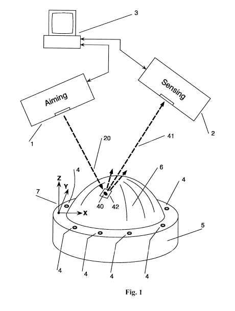
Fig. 1 shows an example lasergrammetry system configured in accordance with an
embodiment of the present invention. As can be seen, the system includes an
aiming laser
projector 1, a sensing projector 2, a computer 3, and a plurality of fiducials
4 associated with
an object 5. According to this embodiment, an example function of the
lasergrammetry
system is to measure 3D coordinates of chosen points on a surface 6 of the
object 5. In this
14
CA 02911841 2015-09-15
WO 2013/148522
PCT/US2013/033550
representative embodiment, the fiducials 4 can be, for instance, retro-
reflective targets
suitable for use in laser projection and photogrammetry applications. The
fiducials 4 are
located in such a way that their 3D coordinates are known with respect to a
coordinate system
7 associated with the object 5.
In some such embodiments, the aiming projector 1 can be implemented, for
example, with a
3D industrial laser projector like the one disclosed in U.S. Patent No.
6,547,397, the entire
disclosure of which is incorporated herein by reference at Appendix A. An
aiming projector 1
configured in accordance with one specific example embodiment is shown in Fig.
2. As can
be seen, the aiming projector I includes a laser 10, a focusable beam expander
II comprising a
negative lens 12 and a positive lens 13, a beam steering system 14, a
controller 15, and an
optical feedback subsystem 16 comprising a pickup clement 17 and a
photodetector 18.
The laser 10 emits a laser beam 19. In some example embodiments, the laser 10
is
implemented with a solid state diode pumped laser that produces light at the
"green"
wavelength of 532 nanometers, although other wavelengths can be used as will
be
appreciated. In some specific cases, the power of the beam 19 output by the
laser 10 is not
more than 5 milliwatts, which happens to correspond to the upper power limit
for class Ma
lasers, and is a continuous wave output. Again, however, the specific laser
parameters such as
wavelength, power, beam shape and diameter, etc can vary from one embodiment
to the next,
and the claimed invention is not intended to be limited to any particular
laser configuration.
In operation, the laser 10 can be turned on and off by the controller 15
during scanning and
projection operations of the laser projector 1. In some example cases, the
laser beam 19 has a
diameter of about 0.4 to 1.0 millimeters. In some embodiments, the beam
expander 11
expands the laser beam about 10 to 15 times. The combination of lenses 12 and
13 also
functions as a focusable beam collimator so that the laser projector output
beam 20 can be
focused on the surface 6 of the object 5. In some example embodiments, note
that the positive
lens 13 can be mounted on a slide (not shown) so it can be moved manually or
automatically
along its optical axis to re-focus the output beam 20 as the distance from the
projector 1 to the
surface 6 may vary.
An example embodiment of the beam steering system 14 is shown in Fig. 3. As
can be seen,
this example beam steering system 14 is implemented as a two-axes galvanometer
based
system. It includes galvanometers 30 and 31. Beam steering mirrors 32 and 33
are mounted
on the corresponding coupling clamps 34 and 35 attached to the shafts of
galvanometers 30
and 31, respectively. The galvanometers are high precision servo motors
containing angular
CA 02911841 2015-09-15
WO 2013/148522
PCT/US2013/033550
position sensors. Example galvanometers that can be used in various
applications for laser
projection include, for example, models 6860 or 6220 made by Cambridge
Technology, Inc.,
USA.
In the process of laser projection in accordance with some such example
embodiments, the
-- controller 15 moves the galvanometers 30 and 31 in coordinated manner.
Light emitted by
the laser 10 strikes, at first, minor 32 which steers the laser beam
horizontally (H angle), and
then it strikes mirror 33 which steers the laser beam vertically (V angle) and
directs it toward
the object surface 6. Here the laser light forms a tightly focused spot 40 (as
shown in Figs. 1,
2, and 4). As will be appreciated, the diameter of the beam spot will depend
on factors such
-- as the distance between the projector 1 and the object surface 6. In one
example
configuration, at a distance of about 5 meters between projector I and the
object surface 6, the
spot 40 has a diameter from about 0.3 to I mm. If laser beam 20 strikes
surface 6 orthogonally
then the shape of spot 40 is circular. Otherwise, its shape on the surface is
elliptical.
With further reference to Fig. 2, the optical feedback pickup element 17 can
be implemented,
-- for example, with a beam splitter that has a transmission-to-reflection
ratio from 50:50 to 90:
10, in accordance with some embodiments. A ratio of 90: 10 may be
advantageous, for
instance, because it is characterized by less beam power loss for the laser
projection. During
the 'bucking-in' operation described below, the aiming projector 1 scans
fiducials 4 with its
laser beam. When retro-reflective targets are used as fiducials, a portion of
the laser light that
-- strikes a fiducial returns back toward beam splitter 17 through beam
steering system 14. Part
of the returned light reflects from the beam splitter 17 toward photodetector
18. In some
example embodiments, the power level of the light reaching the photodetector
18, in the case
of using retro-reflective targets, is in the range of about 10 to about 100
nanowatts. Other
embodiments may exhibit a different power level in this respect, as will be
appreciated. The
-- photodetector 18 can be implemented, for example, with a silicone
photodiode with an
amplifier that has sufficient gain to detect such power level, in accordance
with some specific
example embodiments.
An embodiment the sensing laser projector 2 is shown in Fig. 4. As can be
seen, some of its
components involved in producing, shaping and directing the laser light can be
the same as
-- for the aiming projector, in some embodiments. For instance, in one
specific such
embodiment, laser 10 is the same as laser 10, focusable beam expander 111 with
lenses 112
and 113 is the same as beam expander 11 with lenses 12 and 13, beam steering
system 114 is
the same as beam steering system 14, controller 115 is the same as controller
15, and beam
16
CA 02911841 2015-09-15
WO 2013/148522
PCT/US2013/033550
splitter 117 is the same as beam splitter 17. Consequently, laser beam 119 is
the same as laser
beam 19 and the laser output beam produced by the sensing projector 2 during
its "bucking-
in" operation is the same as the output beam 20 produced by the aiming
projector 1.
However, note that the optical feedback subsystem 45 and its components are
different from
the optical feedback subsystem 16. Beside beam splitter 117, the optical
feedback subsystem
45 of this example embodiment comprises a folding mirror 46, an imaging lens
47, an
aperture mask 48, and a high sensitivity photodetector 49. In some cases,
folding minor 46
has its reflective surface covered with a layer that reflects only light with
the wavelength of
lasers 10 and 110 (e.g., 532 nanometers in one example embodiment). It
therefore works as a
bandpass filter, reducing a background signal originated by ambient light
and/or other
sources. The aperture mask 48 and the photodetector 49 can be mounted together
on slide 50
and they can be translated along the optical axis of lens 47 by the actuator
51 following
commands from the controller 115, in this example embodiment. During
measurement
operation, the optical feedback subsystem 45 of the sensing projector 2
provides sufficient
detection capabilities for the part of laser light 20 that is diffusely
reflected from the object
surface 6. Because of diffusion, reflected laser light 41 (see, for example,
Figs. 1 and 5) is
widely spread back toward the sensing projector 2. A relatively small portion
of this diffusely
reflected light 41 makes its way through the beam steering system 114 toward
the beam
splitter 117, which reflects at least part of reflect light 41 toward other
components of the
optical feedback subsystem 45. In some example embodiments, the power level of
the light
reaching the high sensitivity photodetector 49 during a measurement operation
is in the range
of about 50 to about 500 picowatts, although this range can vary from one
configuration to
the next as will be appreciated in light of this disclosure. The photodetector
49 can be
implemented, for example, with a photo multiplier tube (PMT). Photo multiplier
tubes are
commercially available devices made, for example, by Hamamatsu Ltd., Japan.
Other
suitable photodetector technologies can be used as well, as will be
appreciated.
Fig. 5 shows an optical diagram illustrating between components feedback
subsystem 45 and
the object surface 6 with laser spot 40, in accordance with one example
embodiment. Note
that components 114, 117, and 46 have been omitted from Fig. 5 to provide a
focused
discussion. In accordance with one such embodiment of this present invention,
prior to
scanning laser spot 40 by sensing projector 2, the aperture mask 48 (e.g.,
attached to slide 50
together with photodetector 49) is placed by actuator 51 into a plane 60 that
is optically
conjugate with the part of the surface 6 surrounding spot 40. In other words,
it can be said
17
CA 02911841 2015-09-15
WO 2013/148522
PCT/US2013/033550
that the aperture mask 48 is being "focused". In this example case, "optically
conjugate" is
intended to mean that the lens 47 creates a real image 61 of the spot 40
focused onto the
plane 60. The image is being formed by the optical beam of the diffusely
reflected laser light
41. Aperture mask 48 effectively serves as an image analyzer during scanning
operation by
projector 2. Focusing the aperture mask 48 substantially improves measurement
precision by
reducing the impact of laser light speckles on finding a center of the spot
40, in accordance
with such embodiments.
Alternatively, as will be appreciated in light of this disclosure, the
aperture mask 48 and
photodetector 49 could be mounted fixed but the lens 47 could be translated
along its optical
axis thus bringing the conjugate plane 60 with image 61 into the fixed plane
of the aperture
mask 48.
When spot 40 is being placed on surface 6 by aiming projector I, the rays of
light 41 that are
collected through beam steering system 114 and reflected from beam splitter
117 and folding
mirror 46 are concentrated by the imaging lens 47 into image 61. When the
aperture mask is
focused, the image 61 is formed as a tight spot in the plane of the aperture
mask 48. The real
size of this concentrated image 61 is diffraction limited; in some example
cases, for instance,
it is a spot about 15 to 25 micrometers in diameter, for a spot 40 having an
example diameter,
as previously noted, of about 0.3 to I mm, An example aperture mask 48 is
shown in detail in
Fig. 6, according to one embodiment. In this example case, it is formed by a
pinhole 65 in an
opaque plate 66 oriented transversely to the optical axes of the lens 47. As
the sensing
projector 2 runs its beam steering system 114 to scan the area 42 around spot
40, its image 61
moves across the plate 66. When the image spot 61 crosses pinhole 65, the
laser light goes
through pinhole 65 into photodetector 49. Photodetector 49 converts the light
into electrical
signal and sends it to controller 115.
Numerous other embodiments of a lasergrammetry system with laser projectors
will be
apparent in light of this disclosure. In another embodiment, for instance, a
lasergrammetry
system has the same major components as in the example one illustrated by Fig.
1: an aiming
laser projector I, a sensing projector 2, a computer 3, and a plurality of
fiducials 4 associated
with an object 5. However, the sensing laser projector 2 is enhanced to enable
the object
feature detection in accordance with the solution described in detail in the
previously
incorporated U.S. Patent No. 7,306,339. For the enhancement, in one such
example
embodiment, the aperture mask 48 serves not only as an image analyzer during
measurement
operation but also as spatial filter suppressing internal scattering and
excessive background
18
CA 02911841 2015-09-15
WO 2013/148522
PCT/US2013/033550
light during feature detection operation, in accordance with the teaching of
U.S. Patent No.
7,306,339. Utilizing the sensing projector with object feature detection
capabilities allows for
performance of various advanced types of 3D measurement and in-process
verification, for
example, to combine edge detection with surface or plane fitting through the
designated
measurement points.
As will further be appreciated in light of this disclosure, note that sensing
projector 2 can
serve as an aiming projector. One such approach is implemented in the example
embodiment
illustrated by Fig. 7. This example lasergrammetry system has a symmetrical
architecture and
includes two aiming/sensing projectors 70, a computer 3, and a plurality of
fiducials 71
associated with an object 5. Again, one function of the lasergrammetry system
is to measure
3D coordinates of chosen points on a surface 6 of the object 5. In this
embodiment, the
fiducials 71 could be not only retro-reflective targets but any kind of
contrast geometry
features like holes, fasteners, edges and corners, etc. The laser projectors
70 can be both built
as sensing projector 2, such that they are enhanced to enable the object
feature detection as
previously described. At the same time, both projectors are capable of serving
as aiming
projectors. Thus, for instance, the left projector can project spot 40 and the
right projector can
project spot 72 on the surface 6. Accordingly, in measurement operations, the
right projector,
as sensing, will scan the spot 40 and the left projector, as sensing, will
scan the spot 72. As
will be appreciated in light of this disclosure, such symmetrical system can
achieve better
accuracy by averaging the measurements performed, first, when one projector is
aiming and
the other is sensing and then, second, interchanging them.
Another lasergrammetry system embodiment is illustrated by Fig. 8. As can be
seen, this
example lasergrammetry system does not include a fixed set of fiducials with
known
coordinates. Instead, it includes a free located scale rod 80 with at least
two fiducials 81. The
81 is presumed to or otherwise detectable. In this exemplary embodiment,
fiducials 81 can be
implemented, for instance, with retro-reflective targets. The other components
of the system
depicted in Fig. 8 can be the same as for the first embodiment shown in Fig.
1: aiming laser
projector 1, sensing laser projector 2, and computer 3. Again, in measurement
operation, the
aiming projector 1 produces the spot 40 on the surface 6 of the object 5, and
the sensing
projector 2 scans it. In accordance with this example embodiment, such a
system can be used
for general reverse engineering applications and, as it described further
herein, the system
provides 3D coordinate measurements of a group of points utilizing a bundle
solution method
similar to conventional photogrammetry methods.
19
CA 02911841 2015-09-15
WO 2013/148522
PCT/US2013/033550
In various embodiments, adding an auxiliary video camera associated with the
sensing
projector can further enhance lasergrammetry systems of the type described
herein. This
solution allows speeding up the process of measuring an unknown object
surface. It is
especially effective for a system configuration intended for reverse
engineering applications.
An example of such enhanced embodiment is shown in Fig. 11. The video camera
120 is
associated with the sensing projector 2 and it is connected to the computer 3.
The video camera 120 is a typical industrial CCD or CMOS video camera with a
lens having
its angular field of view that is more or equal to the angular beam steering
range of the
galvanometer beam steering system 14 shown in Fig. 3. The resolution of the
camera has to
be sufficient to detect any spot produced by the aiming projector 1 on the
surface 6 of the
object 5. Typically, the conventional camera resolution of 640 x 480 pixels is
adequate for
the task. This camera has to be initially aligned and calibrated in such way
that its location
and orientation becomes known with respect to the coordinate system of the
sensing projector
2. Camera 120 plays an auxiliary role in the process of measuring an unknown
surface 6 by
helping to speed up the capture of spots projected the aiming projector 1. As
each spot is
being projected, the camera 120 takes a snapshot of its whole field view.
Computer 3
processes the image and determines the location of the spot in the camera
pixel coordinates.
Then, based on known location and orientation of the camera with respect to
the projector,
computer 3 calculates approximate values for the beam steering angles H and V
associated
with the captured spot image. It allows substantially reduce the size of the
predetermined
scan area 42 shown in Fig. 8 or Fig. 11 (or scan areas 85 shown in Fig. 10)
thus reducing the
scan times and speeding up the process of surface measurement.
It should be understood that the embodiment shown in Fig. 11 is only one
example of
integrating an auxiliary video camera with a lasergrammetry system. It is
apparent to anyone
skilled in the art that this solution is also applicable, for example, to
enhance the dual aiming-
sensing configuration illustrated in Fig. 7, so the two cameras could be used,
each associated
with the corresponding projector. (Such configuration is not shown in the
drawings).
Numerous lasergrammetry methods for 3D coordinate measurements and in-process
verification involving laser projectors will also be apparent in light of this
disclosure. For
instance, one example embodiment of a lasergrammetry method is method (M 1)
described
CA 02911841 2015-09-15
WO 2013/148522
PCT/US2013/033550
below for 3D digitizing of the surface of an object. Referring to Fig. 1, this
method relies on
using at least two laser projectors the aiming projector I and the sensing
projector 2.
Furthermore, this method is based on utilizing a fixed set of fiducials 4. The
method MI
includes the following major steps (again, the use of the term steps is not
intended to
implicate a precise order, and other embodiments may have similar
functionality performed
in a different sequence):
M1 -Step A. The aiming projector 1 utilizes its laser beam, optical feedback
capabilities, and
the set of fiducials 4 to determine the location and orientation of the
projector in 3D space
with respect to the object's coordinate system 7. The determination is based
on a given set of
coordinate data for fiducials 4 with respect to the coordinate system 7. This
process referred
herein by the phrase buck into the object's coordinate system. In some
embodiments, a buck-
in solution generally uses sequential scanning of cooperative or retro-
reflective targets or
features by the laser projector's beam as fiducials, processing optical
feedback signals,
finding the angular directional coordinates toward centers of those fiducials,
and then
computing the location and orientation of the projector. In some embodiments,
at least six
fiducial points are used, but other embodiments may user fewer fiducials
(e.g., three) and
other embodiments may user more fiducials (e.g., ten).
Ml-Step B. The sensing projector 2 bucks into the coordinate system 7 in the
same sequence
as described in the MI-Step A for the aiming projector 1.
Ml-Step C. The system performs sequential point-by-point measurement of the
surface 6 and
obtains a series of digitized 3D coordinates of the surface. As will be
appreciated, this
process depends on a particular application. One example of an application is
verification of
the surface 6 by comparing it with a given CAD model. In this case, the point-
by-point
measurement process can be automatic. The CAD model data can be stored, for
example, in
the computer 3. The computer 3 sequentially assigns the points on the surface
6 to be
measured. As the location and orientation of both projectors 1 and 2 arc known
to computer
3, it calculates the beam steering angles for projector 1 to sequentially aim
its laser beam
toward measurement points and the beam steering angles for projector 2 to
locate the centers
of its predetermined scan areas at those points. In one example case, the time
for a one point
measurement provided by the exemplary embodiment of the lasergrammetry system
described above is about 0.5 seconds. Another example application is a
measurement of an
unknown surface. In this case, the point-by-point measurement process can be
semi-
automatic or manual. In an example semi-automatic process, computer 3 can
assign a
21
CA 02911841 2015-09-15
WO 2013/148522
PCT/US2013/033550
regularly spaced array of the beam steering angles for projector 1 to
sequentially aim its laser
beam toward measurement points and an array of the beam steering angles for
projector 2 to
locate the centers of its predetermined scan areas at those points. Because
the surface under
measurement is unknown, this operation may include an additional step of
searching the spot
over a larger area by projector 2 prior to defining its beam steering angles
corresponding to a
center of a final scan area for each point of measurement. In an example
manual process, for
each measurement point, a user moves the aiming beam to a desired point on the
surface 6 by
controlling the projector 1 and by viewing location of the projected spot 40.
The sensing
projector 2 creates a glowing template referred to herein as a "scan box". The
scan box a
predetermined square area 42 on the surface 6 where the scan of spot 40 will
occur.
Ml-Step D. In case of in-process verification, when the CAD model of the
surface is known,
compare measurement results with the model and present the difference in a
convenient form
for the user.
The actual point measurement operation carried out at step C includes the
following steps, in
accordance with one example embodiment:
Ml-Step CI. The aiming projector 1 creates a stationary spot 40 on the surface
6. Computer 3
calculates the aiming ray of the beam 20 based on the given beam steering
angle commands
being sent to the system 14 through controller 15. Because the location and
orientation of
projector 1 with respect to coordinate system are known, the 6 components of
the aiming ray
(the start point coordinates and the directional cosines) can be computed in
the coordinate
system 7. In some such embodiments, the laser 10 stays continuously turned on.
Ml-Step C2. The sensing projector 2 obtains its beam steering commands for the
system 114
from computer 3 through controller 115. They provide allocation of the
predetermined scan
area 42 with its center positioned over the spot 40. In case of manual
measurement pointing, a
scan box can be projected.
Ml-Step C3. Because the location and orientation of projector 2 with respect
to coordinate
system 7 are known, computer 3 can calculate an approximate distance from
projector 2 to
the surface 6. It then provides appropriate information to controller 115
which sends
command to actuator Si thus focusing aperture mask 48. Note that laser 110 can
be turned
off.
Ml-Step C4. The sensing projector 2 scans the area 42 by executing a series of
beam steering
commands from controller 115 to the system 114. In one example embodiment, the
scanning
22
CA 02911841 2015-09-15
WO 2013/148522
PCT/US2013/033550
method is raster scanning, but in various embodiments any other suitable
scanning technique
may be used. During scan, the image 61 of the spot 40 moves across the
aperture masks plate
66. Photodetector 49 converts the captured light into electrical signal and
sends it to
controller 115. Controller 115 samples the optical feedback signal at given
incremental
positions of the beam steering system 114. In other words, projector 2
operates as digitizing
scanner. As the result of this scanning, controller 115 captures a digital
"pixelized" image of
the spot 40 with horizontal pixels representing sampling in the horizontal
beam steering angle
H, and vertical pixels representing sampling in the vertical beam steering
angle V. As will be
appreciated, note that the metric of the digital image captured by the
projector 2 in this
example embodiment is in angular units (radians or degrees).
Ml-Step C5. Controller 115 sends the obtained digital image of the scanned
spot 40 to the
computer 3. The last one calculates the center of the spot image by running an
image
processing algorithm. This algorithm detects an edge of a circular or
elliptical image and
defines its center. Such algorithms can be implemented with conventional or
custom
technology. As will be appreciated, note that computer 3 can calculate the
spot digital image
center in terms of the H and V beam steering angles associated with it. Then
computer 3
calculates the sensing ray - a chief ray or portion of the beam 41 directed
toward the center of
the spot 40. In some specific embodiments, this sensing ray, as the aiming ray
computed in
the M1 -Step Cl, has 6 components: the start point coordinates and the
directional cosines.
Because the location and orientation of projector 2 with respect to coordinate
system 7 are
known, the 6 components of the sensing ray can be computed in the coordinate
system 7.
Ml-Step C6. Computer 3 calculates the X, Y, Z coordinates of the 3D
intersection between
the aiming and sensing rays associated with the given measurement point. Note
that, in
general, the aiming and the sensing rays geometrically do not touch each other
in 3D space.
The math formulas and algorithm of finding an intersection solution as the
closest point to
both lines are well known. The intersection solution is assigned then as the
measurement
result for the given point location.
Another embodiment of a lasergrammetry method (M2) for 3D coordinate
measurements and
in-process verification is based on a lasergrammetry system utilizing an
enhanced sensing
laser projector capable of the object feature detection, such as the example
system shown in
Fig. 7. This method M2, as with the method M1 previously described, relies on
using a fixed
set of fiducials 4. Again, the 3D coordinates of the fiducials are presumed to
be known with
respect to the coordinate system 7. The method M2 solves advanced tasks of 3D
object
23
CA 02911841 2015-09-15
WO 2013/148522
PCT/US2013/033550
measurements, for example, measurement of a given feature edge in 3D space, as
illustrated
in Fig. 9. It shows a drilled hole 90 through the surface 6. In this example
embodiment, the
process of 3D edge location measurement for the hole 90 includes the following
steps:
M2-Step A. The aiming projector bucks into the object coordinate system 7 in
the same
sequence as described above in the Ml-Step A.
M2-Step B. The sensing projector bucks into the coordinate system 7 in the
same sequence as
described in the 21-Step A for the aiming projector.
M2-Step C. Following the step MI-Step C, the lasergrammetry system of this
embodiment
measures 3D coordinates of at least 3 points 91 on surface 6 in the vicinity
of the hole 90.
M2-Step D. Computer 3 runs a surface fitting algorithm through the measured
points 91
defining a small area surface, such as a plane 92, that surrounds the hole 90.
When the points
91 are sufficiently close to the hole 90 the plane 92 accurately coincides
with the part of
surface 6 in the vicinity of hole 90.
M2-Step E. The sensing projector performs a feature detection scan over the
area of hole 90.
It detects the top edge 93 of the hole 90. A detailed description of the
feature edge detection
process by a laser projector with feature detection capabilities, in
accordance with one
example embodiment, is given in the previously incorporated U.S. Patent No.
7,306,339. For
the plurality of edge points 94, the sensing projector determines the
plurality of beam steering
angles H and V associated with them.
M2-Step F. Based on the plurality of beam steering angles, computer 3
calculates a plurality
of sensing rays 95 as chief rays of the sensing projector directed toward the
plurality of edge
points 94. In some such specific embodiments, every computed sensing ray has 6
components: the start point coordinates and the directional cosines. Because
the location and
orientation of the sensing projector with respect to coordinate system 7 are
known, the 6
components of the sensing ray can be computed in the coordinate system 7.
M2-Step G. Computer 3 calculates the X, Y, Z coordinates of 3D intersections
between all
the sensing rays 95 associated with the plurality the edge points 94 and the
plane 92. Any
suitable known math formulas of finding an intersection between a line and a
plane can be
used. The plurality of intersection coordinates X, Y, Z is assigned as the
measurement result
for the edge location.
24
CA 02911841 2015-09-15
WO 2013/148522
PCT/US2013/033550
Another embodiment of a lasergrammetry method (M3) for 3D coordinate
measurements is
intended for general reverse engineering applications involving 3D surface
digitizing and it
can be carried out, for instance, by the embodiment of the lasergrammetry
system shown in
Fig. 8. This method M3 does not require usage of a fixed fiducial set with
known coordinates.
Instead, it utilizes a free located scale rod 80 with at least two fiducials
81. The distance
between fiducials is presumed to be known, or otherwise detectable. The
embodiment this
method M3 is illustrated in Fig. 10. The surface 6 that is needed to be
digitized presumed to
be unknown. Locations and orientations of projectors 1 and 2 with respect to
the object 5 are
also unknown. The method M3 includes the following steps:
M3-Step A. The aiming projector 1 sequentially scans fiducials 81 utilizing
its laser beam
and its optical feedback. The projector's I controller 15 determines the beam
steering angles
H and V associated with each fiducial and defining the rays 82.
M3-Step B. The sensing projector 2 sequentially scans fiducials 81 utilizing
its laser beam
and its optical feedback. The projector's 2 controller 115 determines the beam
steering angles
H and V associated with each fiducial and defining the rays 83.
M3-Step C. The aiming projector 1 sequentially projects stationary spots 84 on
the surface 5
following a set of beam steering angles H and V assigned by user. The rays 86
associated
with those beam steering angles are shown in the Fig. 10.
M3-Step D. At each location of spot 84, the sensing projector 2 sets up a
predetermined scan
area 85 where the scan of spot 84 will occur.
M3-Step E. Following action of projector 1 placing light spots 84, one after
another, the
sensing projector 2 sequentially scans areas 85, one after another. In a
similar fashion as
described with reference to step M3-Step C4, the sensing projector's
controller determines the
beam steering angles II and V for the centers of spots 84. The rays 87
associated with those
beam steering angles are shown in the Fig. 10.
M3-Step F. After all scans are completed, computer 3 runs a bundle solving
calculation that
simultaneously involves the whole set of beam steering angles for all the
measurement points
and the scale bar fiducials and results a set of X, Y, Z coordinates of all
the measurement
points. In some embodiments, the minimum number of measurement points in this
method is
6, although other embodiments may have fewer (e.g., 2 or 3) or more (e.g., 10
or more). The
bundle solving algorithm can be implemented, for instance, using conventional
techniques
applicable to photogrammetry.
CA 02911841 2015-09-15
WO 2013/148522
PCT/US2013/033550
Devices, systems, and methods of the types described herein may exhibit a
number of
advantages over other techniques. For example, in various embodiments,
devices, systems,
and methods of the types described herein may allow a surface to be digitized
without
requiring physical contact between the surface being digitized and the retro-
reflective target
being placed on the surface. Accordingly, systems of the type described herein
may avoid
contact measurements and so may be, e.g., suitable as in-process verification
operations for
many important manufacturing applications, for example producing composite
parts in
aerospace industry. This is in contrast to digitization techniques of the
types described in
U.S. Patent No. 5,661,667.
In some embodiments, devices, systems, and methods of the types described
herein may
allow a surface to be digitized without the need for a laser projector and a
video camera with
a lens and a separate galvanometer scanner (e.g., as described in U.S. Patent
No. 5,615,013).
Accordingly, accuracy losses may be avoided that would result from a
combination of the
camera lens distortion and galvanometer non-linearity. In some applications,
such distortions
may make it practically impossible to achieve a level of accuracy required,
e.g., for modern
aerospace industrial applications. A further advantage is that by avoiding the
need for two
different optical paths for laser projection and camera imaging one eliminates
the necessity
for frequent mutual calibration between the camera imaging system and the
laser projection
system.
In some embodiments, devices, systems, and methods of the types described
herein may
allow a surface to be digitized without the need for a laser projector and one
or two CCD
cameras that can be swiveled in two directions and provided with an optical
zoom function
(e.g., of the type disclosed in US Patent Application Publication No.
2007/0058175 Al),
thereby avoiding the low speed (e.g., due to the requirement for mechanical
actuation of the
swiveling cameras) and accuracy associated with such systems.
In some embodiments, devices, systems, and methods of the types described
herein may
allow for accurate lasergrammetry in 3D space. This is in contrast to systems
of the type
described in U.S. Patent No. 7,306,339. As it stated there, the proposed laser
projector with
object feature detection is capable of detecting a spot projected onto an
object surface by
another laser source. However, as disclosed, it cannot be used for accurate
lasergrammetry in
3D space because it detects the projected laser light with a photodetector
with the pinhole
works as a light collector only. This will introduce substantial errors in
determining the laser
spot location when the object surface is not in a conjugate image plane with
the pinhole.
26
CA 02911841 2015-09-15
WO 2013/148522
PCT/US2013/033550
In some embodiments, devices, systems, and methods of the types described
herein may
allow for feature detection and surface digitizing without the need for an
expensive and
complicated laser radar system, e.g., of the type disclosed in US Patent No.
8,085,388.
The foregoing description of the embodiments of the invention has been
presented for the
purposes of illustration and description. It is not intended to be exhaustive
or to limit the
invention to the precise form disclosed. Many modifications and variations are
possible in
light of this disclosure. It is intended that the scope of the invention be
limited not by this
detailed description, but rather by the claims appended hereto.
27