Note: Descriptions are shown in the official language in which they were submitted.
CA 02911892 2015-11-12
TSN201505258CA
TFN150653-CA
1
FUEL CELL SYSTEM, FUEL CELL VEHICLE, AND CONTROL METHOD FOR FUEL
CELL SYSTEM
BACKGROUND OF THE INVENTION
1. Field of the Invention
[0001] The
invention relates to a fuel cell system used in a fuel cell vehicle, the
fuel cell vehicle, and a method of controlling the fuel cell system.
2. Description of Related Art
[0002] When
a fuel cell is stopped, hydrogen in an anode moves through an
electrolyte membrane into a cathode and is retained in the cathode. Japanese
Patent
Application Publication No. 2008-021485 (JP 2008-021485 A) describes supplying
the
cathode with an oxidant gas in order to dilute and discharge the hydrogen
retained in the
cathode. The oxidant gas is supplied by a pump (an air compressor).
[0003]
However, a fuel cell vehicle does not typically start to run as soon as a
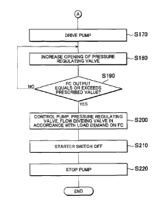
starter switch is switched on, and therefore no load demand is issued to the
fuel cell. In a
condition where no load demand is issued to the fuel cell, it is not
preferable, in
consideration of fuel efficiency and noise vibration (noise and vibration), to
supply the
oxidant gas by driving the air compressor merely in order to dilute and
discharge the
hydrogen retained in the cathode. Moreover, when the oxidant gas is supplied,
the fuel
cell enters a power generation condition, leading to excessive hydrogen
consumption and a
corresponding reduction in fuel efficiency.
SUMMARY OF THE INVENTION
[0004] The
invention provides a fuel cell system, a fuel cell vehicle, and a control
CA 02911892 2015-11-12
TSN201505258CA
TFN150653-CA
2
method for the fuel cell system with which an improvement in fuel efficiency
and a
reduction in noticeable noise vibration can be achieved.
[0005] A
first aspect of the invention relates to a fuel cell system used in a fuel
cell vehicle. The fuel cell system includes: a power supply circuit including
a fuel cell
and a secondary battery; an oxidant gas supply flow passage used to supply an
oxidant gas
to a cathode of the fuel cell; a pump that compresses the oxidant gas and
supplies the
compressed oxidant gas to the cathode, the pump being provided in the oxidant
gas supply
flow passage; and a control unit configured to drive the pump and dilute
hydrogen retained
in the cathode. The control unit is configured to stop supplying the oxidant
gas to the
cathode by stopping an operation of the pump such that dilution of the
hydrogen retained
in the cathode is stopped, while the fuel cell vehicle remains stationary
after a starter
switch of the fuel cell vehicle is switched from an off state to an on state,
or while a load
required of the power supply circuit remains smaller than a predetermined
value after the
starter switch of the fuel cell vehicle is switched from the off state to the
on state.
According to this configuration, the hydrogen retained in the cathode is not
diluted and
discharged from the cathode while the fuel cell vehicle remains stationary or
the load
required of the power supply circuit remains smaller than the predetermined
value.
Therefore, an amount of fuel consumed for purposes other than travel can be
suppressed,
enabling an improvement in fuel efficiency. Moreover, wind noise and road
noise are
generated during travel, making operation noise and vibration generated by the
pump less
noticeable. When the pump is driven while the fuel cell vehicle is stationary,
however,
noise vibration in the pump becomes noticeable. According to this
configuration, the
operation of the pump is stopped as long as the fuel cell vehicle remains
stationary, i.e.
does not start to travel, following startup of the fuel cell vehicle, and as a
result, noise
vibration is not noticeable.
[0006] The
control unit may be configured to supply the oxidant gas to the
cathode such that the hydrogen retained in the cathode is diluted and
discharged from the
cathode, when a predetermined time elapses after the starter switch of the
fuel cell vehicle
is switched from the off state to the on state, even when the fuel cell
vehicle has not yet
CA 02911892 2015-11-12
TSN201505258CA
TFN150653-CA
3
started to travel. While hydrogen is retained in the cathode, a power
generation capacity
of the fuel cell remains low. Before the fuel cell generates power, travel is
performed
using power from the secondary battery. In consideration of the durability of
the
secondary battery, a state of charge (SOC) of the secondary battery is
preferably
maintained within a predetermined range. According to this configuration, the
oxidant
gas is supplied to the cathode in order to dilute the hydrogen retained in the
cathode and
thereby discharge the hydrogen from the cathode, with the result that the fuel
cell becomes
capable of generating power, when the predetermined time elapses following
startup of the
fuel cell vehicle. Hence, the power generation capacity of the fuel cell is
high when the
predetermined time elapses, and therefore travel can be performed thereafter
using power
from the fuel cell. As a result, the SOC of the secondary battery can be
maintained within
the predetermined range.
100071 The
control unit may be configured to supply the oxidant gas to the
cathode such that the hydrogen retained in the cathode is diluted and
discharged from the
cathode, when a load demand is issued to the power supply circuit after the
starter switch
of the fuel cell vehicle is switched from the off state to the on state, even
when the fuel cell
vehicle has not yet started to travel. In consideration of the durability of
the secondary
battery, the SOC of the secondary battery is preferably maintained within the
predetermined range. According to this configuration, the fuel cell is caused
to generate
power when a load demand is issued to the power supply circuit, for example
when power
is required to activate an air conditioner, even before the fuel cell vehicle
starts to travel,
and therefore the SOC of the secondary battery can be maintained within the
predetermined range.
[0008] A
second aspect of the invention relates to a fuel cell vehicle including the
fuel cell system according to the first aspect.
[0009] A
third aspect of the invention relates to a control method for a fuel cell
system used in a fuel cell vehicle. The fuel cell system includes: a power
supply circuit
including a fuel cell and a secondary battery; an oxidant gas supply flow
passage used to
supply an oxidant gas to a cathode of the fuel cell; a pump that compresses
the oxidant gas
CA 02911892 2015-11-12
TSN201505258CA
TFN150653-CA
4
and supplies the compressed oxidant gas to the cathode, the pump being
provided in the
oxidant gas supply flow passage; and a control unit configured to drive the
pump and
dilute hydrogen retained in the cathode. The control method includes stopping
supplying
the oxidant gas to the cathode by stopping an operation of the pump such that
dilution of
the hydrogen retained in the cathode is stopped, while the fuel cell vehicle
remains
stationary after a starter switch of the fuel cell vehicle is switched from an
off state to an on
state, or while a load required of the power supply circuit remains smaller
than a
predetermined value after the starter switch of the fuel cell vehicle is
switched from the off
state to the on state.
10010] According to
this configuration, similarly to the first aspect, an
improvement in fuel efficiency and a reduction in noticeable noise vibration
can be
achieved.
BRIEF DESCRIPTION OF THE DRAWINGS
10011]
Features, advantages, and technical and industrial significance of
exemplary embodiments of the invention will be described below with reference
to the
accompanying drawings, in which like numerals denote like elements, and
wherein:
FIG 1 is an illustrative view showing a vehicle installed with a fuel cell;
FIG. 2 is an illustrative view showing a fuel cell system of the fuel cell
vehicle;
FIGS. 3A and 3B are schematic illustrative views showing the fuel cell;
FIGS. 4A and 4B are flowcharts showing control for discharging hydrogen from a
cathode according to a first embodiment;
FIGS. 5A to 5G are timing charts according to the first embodiment;
FIG 6 is a flowchart showing control for discharging hydrogen from the cathode
according to a comparative example;
FIGS. 7A to 7G are timing charts according to the comparative example;
FIG. 8 is a flowchart showing control for discharging hydrogen from the
cathode
CA 02911892 2015-11-12
TSN201505258CA
TFN150653-CA
according to a second embodiment;
FIGS. 9A to 9G are timing charts according to the second embodiment;
FIG. 10 is a flowchart showing control for discharging hydrogen from the
cathode
according to a third embodiment;
5 FIGS. 11A to 11G are timing charts according to the third embodiment;
FIG. 12 is a flowchart showing control for discharging hydrogen from the
cathode
according to a fourth embodiment; and
FIGS. 13A to 13G are timing charts according to the fourth embodiment.
DETAILED DESCRIPTION OF EMBODIMENTS
100121
First, a first embodiment will be described. FIG. 1 is an illustrative view
showing a vehicle installed with a fuel cell. A fuel cell vehicle 10 includes
a fuel cell 100,
a control unit 110 (also referred to as an electronic control unit (ECU)), a
starter switch 115,
a required output detection unit 120, a speedometer 125, a secondary battery
130, a power
split controller 140, a drive motor 150, a drive shaft 160, a power split gear
170, and
vehicle wheels 180.
100131 The
fuel cell 100 is a power generation apparatus for extracting power by
inducing an electrochemical reaction between a fuel gas and an oxidant gas.
The control
unit 110 controls operations of the fuel cell 100 and the secondary battery
130 on the basis
of a required output value obtained from the required output detection unit
120. The
required output detection unit 120 detects a depression amount of an
accelerator (not
shown) of the fuel cell vehicle 10, and from the magnitude of the depression
amount
detects a required output from a driver. The control unit 110 calculates a
required power
amount required of the fuel cell 100 from the required output. The starter
switch 115 is a
main switch used to start and stop the fuel cell vehicle 10. The speedometer
125
measures a travel speed of the fuel cell vehicle 10. The speedometer 125
obtains the
travel speed of the fuel cell vehicle 10 by measuring one of a rotation speed
of the drive
CA 02911892 2015-11-12
TSN201505258CA
TFN150653-CA
6
motor 150, a rotation speed of the drive shaft 160, a rotation speed of the
power split gear
170, and a rotation speed of the vehicle wheels 180. The secondary battery 130
is used as
a power supply for moving the fuel cell vehicle 10 when an amount of power
generated by
the fuel cell 100 is small, such as immediately after the fuel cell vehicle 10
is started. A
nickel hydrogen battery or a lithium ion battery, for example, may be employed
as the
secondary battery 130. The secondary battery 130 may be charged either
directly using
power output from the fuel cell 100, or by regenerating kinetic energy
generated by the
fuel cell vehicle 10 while decelerating using the drive motor 150, for
example. The
power split controller 140 controls an amount of power fed to the drive motor
150 from the
fuel cell 100 and an amount of power fed to the drive motor 150 from the
secondary
battery 130 in response to a command from the control unit 110. Further, when
the fuel
cell vehicle 10 decelerates, the power split controller 140 feeds power
regenerated by the
drive motor 150 to the secondary battery 130 in response to a command from the
control
unit 110. The power split controller 140, the fuel cell 100, and the secondary
battery 130
together constitute a power supply circuit. The drive motor 150 functions as a
motor used
to move the fuel cell vehicle 10. Further, when the fuel cell vehicle 10
decelerates, the
drive motor 150 functions as a power generator used to regenerate the kinetic
energy of the
fuel cell vehicle 10 as electric energy. The drive shaft 160 is a rotary shaft
for
transmitting driving force generated by the drive motor 150 to the power split
gear 170.
The power split gear 170 distributes the driving force between the left and
right vehicle
wheels 180.
[0014] FIG 2
is an illustrative view showing a fuel cell system of the fuel cell
vehicle 10. The fuel cell vehicle 10 includes the fuel cell 100, a fuel gas
supply circuit
200, an oxidant gas supply circuit 300, an off-gas circuit 400, and a cooling
circuit 500.
[0015] The fuel gas
supply circuit 200 includes a fuel gas tank 210, a fuel gas
supply pipe 220, a fuel gas exhaust pipe 230, a fuel gas recirculation pipe
240, a main stop
valve 250, a regulator 260, a gas-liquid separator 280, and a hydrogen pump
290. The
fuel gas tank 210 stores a fuel gas. In this embodiment, hydrogen is used as
the fuel gas.
The fuel gas tank 210 is connected to the fuel cell 100 by the fuel gas supply
pipe 220.
CA 02911892 2015-11-12
TSN201505258CA
TFN150653-CA
7
The main stop valve 250 and the regulator 260 are provided in the fuel gas
supply pipe 220
in that order from the fuel gas tank 210 side. The main stop valve 250
switches a supply
of fuel gas from the fuel gas tank 210 between an on state and an off state.
The regulator
260 adjusts a pressure of the fuel gas supplied to the fuel cell 100.
[0016] The fuel gas
exhaust pipe 230 discharges fuel off-gas from the fuel cell
100. The fuel gas recirculation pipe 240 is connected to the fuel gas exhaust
pipe 230 and
the fuel gas supply pipe 220. The gas-liquid separator 280 is provided between
the fuel
= gas exhaust pipe 230 and the fuel gas recirculation pipe 240. The fuel
off-gas contains
unconsumed hydrogen, nitrogen that has passed through the fuel cell 100, and
water. The
gas-liquid separator 280 separates the water contained in the fuel off-gas
from the gases
(hydrogen and nitrogen) contained therein. Further, the hydrogen pump 290 is
provided
in the fuel gas recirculation pipe 240. In the fuel cell system, the fuel off-
gas is supplied
to the fuel cell 100 using the fuel gas recirculation pipe 240 and the
hydrogen pump 290,
whereupon the hydrogen in the fuel off-gas is used to generate power.
[0017] The oxidant
gas supply circuit 300 includes an air cleaner 310, an air
compressor 320 (also referred to as a "pump 320"), an oxidant gas supply pipe
330 (also
referred to as an "oxidant gas supply flow passage 330"), an atmospheric
pressure sensor
350, an outside air temperature sensor 360, an air flow meter 370, a supplied
gas
temperature sensor 380, and a supplied gas pressure sensor 390. In the fuel
cell 100
according to this embodiment, air (oxygen in air) is used as the oxidant gas.
The air
cleaner 310 removes dust and dirt from the air when the air is taken in. The
pump 320
compresses the air and feeds the air to the fuel cell 100 through the oxidant
gas supply pipe
330. The oxidant gas supply pipe 330 connects the pump 320 to the fuel cell
100 (a
cathode to be described below). The atmospheric pressure sensor 350 measures
the
atmospheric pressure. The outside air temperature sensor 360 obtains a
temperature of
the air before being taken in. The air flow meter 370 measures a flow rate of
the intake
air. The flow rate is substantially identical to the amount of air supplied to
the fuel cell
100. Note that the flow rate of the air varies according to a rotation speed
of the pump
320. The supplied gas temperature sensor 380 measures the temperature of the
air
CA 02911892 2015-11-12
TSN201505258CA
TFN150653-CA
8
supplied to the fuel cell 100, while the supplied gas pressure sensor 390
measures the
pressure of the air supplied to the fuel cell 100.
[0018] The
off-gas circuit 400 includes an off-gas pipe 410, a pressure regulating
valve 420, a fuel gas exhaust pipe 430, an exhaust drain valve 440, an oxidant
gas bypass
pipe 450, and a flow dividing valve 460. The off-gas pipe 410 discharges
oxidant off-gas
from the fuel cell 100. The pressure regulating valve 420 is provided in the
off-gas pipe
410. The pressure regulating valve 420 regulates the pressure of the air in
the fuel cell
100. The fuel gas exhaust pipe 430 connects the gas-liquid separator 280 to
the off-gas
pipe 410. The exhaust drain valve 440 is provided in the fuel gas exhaust pipe
430. The
control unit 110 (FIG. 1) opens the exhaust drain valve 440 in order to
discharge water and
gas (mainly nitrogen) when a nitrogen concentration of the fuel off-gas
increases or an
amount of water in the gas-liquid separator 280 increases. Hydrogen is also
discharged at
this time. In this embodiment, the fuel gas exhaust pipe 430 is connected to
the off-gas
pipe 410 such that the hydrogen in the discharged gas is diluted by the
oxidant off-gas.
The oxidant gas bypass pipe 450 connects the oxidant gas supply pipe 330 to
the off-gas
pipe 410. The flow dividing valve 460 is provided in a connecting portion
between the
oxidant gas bypass pipe 450 and the oxidant gas supply pipe 330. When the
control unit
110 (FIG. 1) opens the exhaust drain valve 440 in order to discharge water and
gas (mainly
nitrogen), the control unit 110 also opens the flow dividing valve 460 such
that air flows
into the oxidant gas bypass pipe 450 and dilutes the hydrogen therein.
Further, as will be
described below, when hydrogen in the cathode of the fuel cell 100 is
discharged during
startup of the fuel cell vehicle 10, the control unit 110 opens the flow
dividing valve 460
such that air flows into the oxidant gas bypass pipe 450 and dilutes the
hydrogen therein.
The off-gas pipe 410 serves as both an oxidant gas discharge flow passage and
a fuel gas
discharge flow passage.
[0019] The
cooling circuit 500 includes a cooling water supply pipe 510, a
cooling water exhaust pipe 515, a radiator pipe 520, a water pump 525, a
radiator 530, a
bypass pipe 540, and a three-way valve 545. The cooling water supply pipe 510
is a pipe
for supplying cooling water to the fuel cell 100, and the water pump 525 is
disposed in the
CA 02911892 2015-11-12
TSN201505258CA
TFN150653-CA
9
cooling water supply pipe 510. The cooling water exhaust pipe 515 is a pipe
for
discharging the cooling water from the fuel cell 100. A downstream portion of
the
cooling water exhaust pipe 515 is connected to the radiator pipe 520 and the
bypass pipe
540 via the three-way valve 545. The radiator 530 is provided in the radiator
pipe 520.
A radiator fan 535 is provided in the radiator 530. The radiator fan 535 feeds
air to the
radiator 530, thereby promoting heat radiation from the radiator 530. A
downstream
portion of the radiator pipe 520 and a downstream portion of the bypass pipe
540 are
connected to the cooling water supply pipe 510.
[0020] The
cooling water is supplied to the fuel cell 100 through the cooling
water supply pipe 510 by the water pump 525 in order to cool the fuel cell
100. The
cooling water is warmed by heat recovered from the fuel cell 100, and is then
discharged
through the cooling water exhaust pipe 515. The warmed cooling water is
distributed
between the radiator pipe 520 and the bypass pipe 540 by the three-way valve
545. The
cooling water that flows to the radiator pipe 520 is cooled by the radiator
530, but the
cooling water that flows to the bypass pipe 540 is not cooled. A temperature
of the
cooling water in the cooling circuit 500 is controlled in accordance with a
ratio at which
the cooling water is distributed to the radiator pipe 520 and the bypass pipe
540 by the
three-way valve 545, the outside air temperature, and an air flow from the
radiator fan 535.
[0021] FIGS.
3A and 3B are schematic illustrative views showing the fuel cell.
The fuel cell 100 includes an electrolyte membrane 101, a cathode side
catalyst layer 102,
an anode side catalyst layer 103, a cathode side gas flow passage 104, and an
anode side
gas flow passage 105. The cathode side catalyst layer 102 and the cathode side
gas flow
passage 104 will be referred to collectively as a cathode, while the anode
side catalyst layer
103 and the anode side gas flow passage 105 will be referred to collectively
as an anode.
The electrolyte membrane is a proton-conductive electrolyte membrane formed
using a
fluorine-based electrolyte membrane resin (an ion exchange resin) such as a
perfluorocarbon sulfonic acid polymer, for example. The cathode side catalyst
layer 102
and the anode side catalyst layer 103 contain carbon supporting a catalyst
(platinum, for
example). The cathode side gas flow passage 104 is a flow passage for
supplying air to
CA 02911892 2015-11-12
TSN201505258CA
TFN150653-CA
the cathode side catalyst layer 102, and includes a gas diffusion layer formed
from carbon
paper and a porous member such as expanded metal. The anode side gas flow
passage
105 is a flow passage for supplying air to the anode side catalyst layer 103,
and includes a
gas diffusion layer formed from carbon paper and a serpentine flow passage
formed from a
5 separator (not shown).
[0022] FIG.
3A is an illustrative view illustrating a reason why hydrogen is
retained in the cathode. When the starter switch 115 of the fuel cell vehicle
10 is
switched off such that the fuel cell vehicle 10 and the fuel cell system
thereof are stopped,
the main stop valve 250 and the regulator 260 of the fuel gas supply circuit
200 (FIG 2)
10 are
closed, and the hydrogen pump 290 is likewise stopped. As a result, hydrogen
is no
longer supplied to the anode of the fuel cell 100. Hydrogen remains in the
anode,
however, and since hydrogen diffuses easily, the hydrogen passes through the
electrolyte
membrane 101 and diffuses to the cathode side. When a state of equilibrium is
achieved
between respective partial pressures of the hydrogen in the cathode and the
anode, the
respective partial pressures of the hydrogen in the cathode and the anode
remain constant.
When hydrogen remains in the cathode, a power generation capacity of the fuel
cell 100
decreases, and therefore the hydrogen is preferably discharged.
[0023] FIG.
3B is an illustrative view illustrating discharge of the hydrogen in the
cathode. The control unit 110 adjusts an opening of the flow dividing valve
460 such that
a small amount of air (4%, for example) flows to the fuel cell 100 and a large
amount of air
(96%, for example) flows to the oxidant gas bypass pipe 450. The control unit
110 then
drives the pump 320 and gradually opens the pressure regulating valve 420 such
that air is
supplied to the cathode of the fuel cell 100. In this embodiment, the pump 320
pumps air
at a flow rate of 1000 L/min, for example, of which 4% (40 L/min) flows to the
fuel cell
100 and 96% (960 L/min) flows to the oxidant gas bypass pipe 450. The flow
rate is set
at 1000 L/min in consideration of noise vibration (noise and vibration) in the
pump 320.
This flow rate, which is employed when the fuel cell vehicle 10 is stopped, is
set
appropriately, in consideration of noise vibration, at a smaller value than
the flow rate of
the air supplied to the fuel cell 100 when a normal operation is underway in
the fuel cell
CA 02911892 2015-11-12
TSN201505258CA
TFN150653-CA
11
vehicle 10. The hydrogen in the cathode is purged from the cathode and thus
discharged
from the fuel cell 100. The hydrogen discharged at this time is diluted by the
air flowing
through the oxidant gas bypass pipe 450 and released into the atmosphere. The
hydrogen
concentration of the released gas is preferably no higher than 4%.
[0024] FIGS. 4A and
4B are flowcharts showing control for discharging hydrogen
from the cathode according to a first embodiment. FIGS. 5A to 5G are timing
charts
according to the first embodiment. In FIGS. 5A to 5G, shaded parts indicate
locations
where various values may be obtained, depending on operating conditions of the
fuel cell
vehicle 10. As shown in FIG. 5F, the hydrogen retained in the cathode
increases
gradually after the starter switch 115 is switched off until a state of
equilibrium is reached.
In step S100, the starter switch 115 of the fuel cell vehicle 10 is switched
on. In step
S110, the control unit 110 opens the pressure regulating valve 420 to an
opening start
position. The pressure regulating valve 420 is opened to the opening start
position in
order to obtain a starting point from which the control unit 110 determines
the opening of
the pressure regulating valve 420.
[0025] The
control unit 110 then drives the pump 320 in step S120, and opens the
pressure regulating valve 420 for a fixed period in step S130. These two
processes are
implemented to turn negative pressure in the cathode of the fuel cell 100 into
positive
pressure. In step S140, the control unit 110 closes the pressure regulating
valve 420 and
stops the air compressor. The pressure regulating valve 420 may be set in the
opening
start position. In step S150, the control unit 110 adjusts the opening of the
flow dividing
valve 460 so that when air is supplied by the air compressor in a subsequent
process, a
small amount of air (4%, for example) flows to the fuel cell 100 and a large
amount of air
(96%, for example) flows to the oxidant gas bypass pipe 450. The control unit
110 then
waits in this condition for the fuel cell vehicle 10 to start traveling.
[0026] In
step S160, the control unit 110 determines from the value of the
speedometer 125 whether or not the fuel cell vehicle is stationary (i.e. not
traveling).
When the fuel cell vehicle 10 is stationary, the control unit 110 continues to
wait. When
the fuel cell vehicle 10 is not stationary, the control unit 110 advances the
processing to
CA 02911892 2015-11-12
TSN201505258CA
TFN150653-CA
12
step S170. Power required for travel at this time is supplied by the secondary
battery 130,
for example. Note that when the fuel cell vehicle 10 travels at a very low
speed (a speed
no higher than 5 km/h, for example) rather than being completely stationary (a
speed of 0
km/h), the control unit 110 may determine that the fuel cell vehicle 10 is
stationary in the
determination of step S160.
[0027] Once
the fuel cell vehicle starts to travel, the control unit 110 drives the
pump 320 in step S170. In consideration of noise vibration, the rotation speed
of the
pump 320 at this time is preferably set to be lower than the rotation speed of
the air
compressor during a normal operation. In step S180, the control unit 110
gradually opens
the pressure regulating valve 420. Accordingly, as shown in FIG 5, the
hydrogen in the
cathode of the fuel cell 100 is discharged so as to gradually decrease,
whereby the output
(an output voltage) of the fuel cell 100 gradually increases.
[0028] In
step S190, the control unit 110 determines whether or not the output of
the fuel cell 100 has reached or exceeded a predetermined value. In this
embodiment, the
control unit 110 determines whether or not a voltage per cell equals or
exceeds 0.6 V.
When hydrogen remains in the cathode, an electromotive force of the fuel cell
100 is low,
but as the amount of hydrogen in the cathode decreases, the electromotive
force gradually
increases. When the voltage per cell equals or exceeds 0.6 V, it may be
determined that
substantially all of the hydrogen in the cathode has been discharged. When the
voltage
per cell equals or exceeds 0.6 V, the control unit 110 advances the processing
to step S200.
In step S200, the control unit 110 controls the respective openings of the
pump 320, the
pressure regulating valve 420, and the flow dividing valve 460 in accordance
with a load
required of the fuel cell 100. When the starter switch 115 is switched off in
step S210, the
control unit 110 advances the processing to step S220, where the pump 320 is
stopped.
[0029] FIG. 6 is a
flowchart showing control for discharging hydrogen from the
cathode according to a comparative example. The comparative example differs
from the
first embodiment in that the processing of steps S130, S140, and S160 is not
executed.
More specifically, in the first embodiment, the hydrogen in the cathode of the
fuel cell 100
is not discharged until the fuel cell vehicle 10 starts to travel, whereas in
the comparative
CA 02911892 2015-11-12
TSN201505258CA
TFN150653-CA
13
example, the processing for discharging hydrogen from the cathode of the fuel
cell 100 is
executed when the starter switch 115 is switched on in step S100, without
determining
whether or not the fuel cell vehicle 10 is stationary.
[0030] FIGS.
7A to 7G are timing charts according to the comparative example.
In the first embodiment shown in FIGS. 5A to 5G, the fuel cell 100 reaches a
voltage at
which a normal operation is possible after the fuel cell vehicle 10 starts to
travel, whereas
in the comparative example shown in FIGS. 7A to 7G, the fuel cell 100 reaches
the voltage
at which a normal operation is possible before the fuel cell vehicle 10 starts
to travel.
Once the fuel cell 100 reaches the voltage at which a normal operation is
possible, fuel is
consumed. In the comparative example, therefore, fuel consumption begins
earlier than
in the first embodiment. As a result, the fuel efficiency deteriorates due to
the fuel
consumed before the fuel cell vehicle 10 starts to travel.
[0031]
According to the first embodiment, described above, the fuel cell 100
starts to consume fuel after the fuel cell vehicle 10 starts to travel, and
therefore an
improvement in fuel efficiency can be achieved in comparison with the
comparative
example. Further, when the fuel cell vehicle 10 travels, wind noise, road
noise, and
vibration are generated. Wind noise and road noise are both loud, and
therefore, when the
pump 320 is driven after the fuel cell vehicle 10 starts to travel, noise
vibration
accompanying driving of the pump 320 becomes less noticeable due to the wind
noise and
road noise.
[0032] Next,
a second embodiment will be described. FIG 8 is a flowchart
showing control for discharging hydrogen from the cathode according to the
second
embodiment. The second embodiment differs from the first embodiment in that
step
S230 is inserted before step S160. In step S230, the control unit 110
determines whether
or not a predetermined time (a predetermined time (ti)) has elapsed after
switching the
starter switch 115 on. In the second embodiment, the predetermined time (ti)
is set at one
minute. When the predetermined time (t 1) has elapsed after switching the
starter switch
115 on, the control unit 110 advances the processing to step S170 regardless
of whether or
not the fuel cell vehicle 10 is stationary (step S160).
CA 02911892 2015-11-12
TSN201505258CA
TFN150653-CA
14
[0033] FIGS.
9A to 9G are timing charts according to the second embodiment.
In the first embodiment shown in FIGS. 5A to 5G, the pump 320 is driven and
the pressure
regulating valve 420 is opened, whereby the amount of hydrogen retained in the
cathode of
the fuel cell 100 starts to decrease and the output of the fuel cell 100
starts to increase, at a
point where the speed of the fuel cell vehicle 10 starts to increase. In the
second
embodiment, the pump 320 is driven and the pressure regulating valve 420 is
opened,
whereby the amount of hydrogen retained in the cathode of the fuel cell 100
starts to
decrease and the output of the fuel cell 100 starts to increase, at a point
where the
predetermined time (the predetermined time (t1)) elapses after switching the
starter switch
115 on. Note that when the fuel cell vehicle 10 starts to travel before the
predetermined
time (ti) elapses, the processing described in the first embodiment is
performed. With the
second embodiment, as is evident from FIGS. 9A to 9G, the fuel efficiency can
be
improved in comparison with the comparative example. Note that in the second
embodiment, the predetermined time (ti) is set at one minute, but the time
from the point
at which the starter switch 115 is switched on to the point at which the fuel
cell vehicle 10
starts to travel differs from driver to driver. Hence, the control unit 110
may modify the
predetermined time Op on the basis of an operation history of the fuel cell
vehicle 10, or
more specifically past times from the point at which the starter switch 115 is
switched on
to the point at which the fuel cell vehicle 10 starts to travel. For example,
the
predetermined time (t 1) may be set at 80% of an average past time.
Alternatively, the
predetermined time (t 1 ) may be set at (average past time ¨ 20 seconds).
When, in this
case, the time from the point at which the starter switch 115 is switched on
to the point at
which the fuel cell vehicle 10 starts to travel is too long, for example more
than five
minutes, the control unit 110 may calculate an average value with substituting
five minute
for the time longer than five minutes.
100341
According to the second embodiment described above, the hydrogen in the
cathode of the fuel cell 100 is discharged once the predetermined time (ti)
elapses, even
when the fuel cell vehicle 10 has not yet started to travel, whereby the fuel
cell 100
becomes capable of generating power. Before the fuel cell 100 generates power,
the fuel
CA 02911892 2015-11-12
TSN201505258CA
TFN150653-CA
cell vehicle 10 travels using power from the secondary battery 130. In
consideration of
the durability of the secondary battery, a SOC of the secondary battery 130 is
preferably
maintained within a predetermined range. According to this embodiment, the
power
generation capacity of the fuel cell 100 is high at the point where the
predetermined time
5 (tl)
elapses, and therefore the fuel cell vehicle 10 can travel using power from
the fuel cell
100 thereafter. As a result, the SOC of the secondary battery 130 can be
maintained
within the predetermined range.
[0035] Next,
a third embodiment will be described. FIG 10 is a flowchart
showing control for discharging hydrogen from the cathode according to the
third
10 embodiment. The third embodiment differs from the second embodiment in that
step
S240 is inserted between step S230 and step S160. In step S240, the control
unit 110
determines whether or not a required power (a required load) of the fuel cell
vehicle 10
equals or exceeds a predetermined value. The required power of the fuel cell
vehicle 10
equals or exceeds the predetermined value (a predetermined value (P1)) when,
for example,
15 a power
consumption of an air conditioner (not shown) is large or the like. Note that
when an amount of power stored in the secondary battery 130 is small, the
control unit 110
may reduce the predetermined value (P1). When the required power of the fuel
cell
vehicle 10 equals or exceeds the predetermined value, the control unit 110
advances the
processing to step S170 regardless of whether or not the predetermined time
(ti) has
elapsed after switching the starter switch 115 on and whether or not the fuel
cell vehicle 10
is stationary.
[0036] FIGS.
11A to 11G are timing charts according to the third embodiment.
In the third embodiment, the pump 320 is driven and the pressure regulating
valve 420 is
opened, whereby the amount of hydrogen retained in the cathode of the fuel
cell 100 starts
to decrease and the output of the fuel cell 100 starts to increase, at a point
where the air
conditioner is activated. Note that when the air conditioner is activated
after the
predetermined time (ti) elapses or after the fuel cell vehicle 10 starts to
travel, the
corresponding processing described in the second embodiment or the first
embodiment is
performed. With the third embodiment, as is evident from FIGS. 11A to 11G, the
fuel
CA 02911892 2015-11-12
TSN201505258CA
TFN150653-CA
16
efficiency can be improved in comparison with the comparative example.
Further, when
a load demand is issued to the power supply circuit (when a load is required
of the power
supply circuit), the fuel cell is caused to generate power, and therefore the
SOC of the
secondary battery can be maintained within the predetermined range.
[0037] Next, a fourth
embodiment will be described. FIG 12 is a flowchart
showing control for discharging hydrogen from the cathode according to the
fourth
embodiment. In the first embodiment, the processing for discharging the
hydrogen in the
cathode of the fuel cell 100 is executed after the fuel cell vehicle 10 starts
to travel,
whereas in the fourth embodiment, the processing for discharging the hydrogen
in the
cathode of the fuel cell 100 is executed after the starter switch 115 is
switched on. In
comparison with the comparative example, however, the hydrogen discharge
processing is
performed slowly.
[0038] The
processing of steps S100 to S140 is identical to the first embodiment.
In step S250, the control unit 110 opens the flow dividing valve 460 so as to
realize a
predetermined ratio (4:96, for example) between the amount of air supplied to
the fuel cell
100 and the amount of air flowing to the oxidant gas bypass pipe 450. The
control unit
110 then opens the pressure regulating valve slightly in step S260, and drives
the pump
320 in step S270. The rotation speed of the pump 320 is preferably set such
that the noise
vibration that accompanies rotation of the pump 320 does not exceed a
predetermined
value.
[0039] In
step S280, the control unit 110 slowly increases the opening of the
pressure regulating valve 420. The opening of the pressure regulating valve
420 is
preferably increased at a lower speed than in step S180 of the first
embodiment. As a
result, the hydrogen in the cathode of the fuel cell 100 is discharged such
that the output of
the fuel cell gradually increases. In step S290, the control unit 110
determines whether or
not the output of the fuel cell 100 has reached or exceeded a predetermined
value.
Similarly to the first embodiment, the control unit 110 determines whether or
not the
voltage per cell equals or exceeds 0.6 V. When the voltage per cell equals or
exceeds 0.6
V, the control unit 110 advances the processing to step S200.
CA 02911892 2015-11-12
TSN201505258CA
TFN150653-CA
17
100401 When
the output of the fuel cell 100 has not reached or exceeded the
predetermined value in step S290, the control unit 110 advances the processing
to step
S160. In step S160, the control unit 110 determines whether or not the fuel
cell vehicle
is stationary. When the fuel cell vehicle 10 is stationary, the control unit
110 advances
5 the
processing to step S280, and when the fuel cell vehicle 10 is not stationary,
or in other
words when the fuel cell vehicle 10 has started to travel, the control unit
110 advances the
processing to step S170. The processing of steps S170, S180, and S190 is
identical to the
first embodiment. In other words, similar processing to the first embodiment
is
performed after the fuel cell vehicle 10 starts to travel.
10 100411 FIGS. 13A
to 13G are timing charts according to the fourth embodiment.
In the fourth embodiment, the processing for discharging the hydrogen in the
cathode of
the fuel cell 100 is executed after the starter switch 115 is switched 5 n. In
comparison
with the comparative example, however, the hydrogen discharge processing is
performed
slowly. In comparison with the comparative example, therefore, the voltage
generated by
the fuel cell remains low until the fuel cell vehicle 10 starts to travel, and
as a result, the
power consumption is also small. Moreover, an amount by which the pump 320 is
driven
before the fuel cell vehicle 10 starts to travel is also small, which is
advantageous in terms
of noise vibration.
[0042] An
embodiment of the invention was described above on the basis of
several examples, but the above embodiment of the invention is provided merely
for the
purpose of facilitating understanding of the invention, and the invention is
not limited
thereto. This embodiment of the invention may be modified and improved without
departing from the concept of the invention and the scope of the claims, and
these
equivalent embodiments are included in the invention.