Note: Descriptions are shown in the official language in which they were submitted.
TITLE: PASSIVE ARC CONTROL WITH SEQUESTERED PHASES IN A
VERTICAL BUS SYSTEM OF A MOTOR CONTROL CENTER
BACKGROUND OF THE INVENTION
1. FIELD OF THE INVENTION
[0001] The invention disclosed relates to arc resistant electrical
distribution
equipment.
2. DISCUSSION OF THE RELATED ART
[0002] Circuit breakers are used in motor control units, wherein the
motor control
unit may be inserted or removed from a motor control center (MCC) switchgear
cabinet
without shutting down all power to the cabinet. The motor control units have a
connected
position in which female connectors of the breakers are connected to
respective bus bars,
and a disconnected position in which the female connectors are disconnected
from the bus
bars. To cover access to, and prevent inadvertent contact with, the bus bars
when the
motor control unit is in the disconnected position, a common shutter system
has been
utilized across all power phases supplying the motor control unit.
[0003] Motor control units may have the requirement of making and
breaking
connections with installed bus bars or bus bar extensions i.e. the incoming
power
conductors contained in the MCC. The making and breaking of connections and
the
handling of heavy currents in the area of connection between control devices
like circuit
interrupters (breakers), makes this area of the cabinet particularly
susceptible to arcing.
An arc flash is the rapid release of energy due to an arcing fault between
phases, neutral
-1-
Date Recue/Date Received 2022-05-25
CA 02912085 2015-11-13
or ground contacts. The resulting arc flash has the potential to cause
considerable
damage, including arcing-induced erosion of the contacts and injury to
operators. The
temperature of an arc flash may be capable of vaporizing metal and sending a
blast of
plasma and molten metal in all directions with extreme force. Damage may be
caused to
the switchgear both by the explosion of the arc flash and by the heat
radiating from the
blast. It is important to minimize the potential for harm to equipment and
people by
containing and redirecting the arc energy out from the switchgear and away
from
personnel.
[0004] Arc resistance pertains to the ability to withstand the destructive
energy
released during an arc flash, by interrupting and channeling the energy away
from
personnel and adjacent equipment. Passive arc resistance may include directed
venting of
the arc flash energy and gases out of the switchgear and reinforcement of the
switchgear
structure to withstand the blast. An example of passive arc resistance from
the applicant
features so-called arc-block technology which provides capability to passively
attenuate
and extinguish arc events, and which is described in the co-pending US Patent
Application Serial Number 13/452,145, filed April 20, 2012, entitled "Passive
Arc
Management System With Flue Chamber", of common ownership herewith. The co-
pending application describes an electrical distribution cabinet has an arc
attenuating
chamber surrounding the electrical connection point between a cluster, i.e.
electrical
power connector, of a draw out circuit breaker and a bus bar extension. The
arc
attenuating chamber is formed by sliding a cluster shield surrounding a
cluster at the back
of the breaker, into a slightly larger arc attenuating box that surrounds the
bus bar
extension, so that the leading edges of the cluster shield and arc attenuating
box overlap
and form the chamber. The arc attenuating chamber provides a flue channel that
lengthens the arc and attenuates the current and temperature until the arc is
extinguished.
SUMMARY OF THE INVENTION
[0005] Example embodiments of the invention minimize the potential for harm
to
equipment and people by containing and redirecting the arc energy out from the
MCC.
[0006] In an example embodiment of the invention, an independently-moveable
arc-resistant shutter assembly fits inside an arc attenuating box surrounding
and
-2-
CA 02912085 2015-11-13
sequestering an individual, vertical bus bar phase at the point of electrical
connection
between a circuit interrupting device, and the vertical bus bar. Sides of the
arc attenuating
box with overlaping geometry separate and sequester one vertical bus bar phase
from an
adjacent vertical bus bar phase, a physical barrier to arc flash energy and
gases intruding
into an adjacent box surrounding an adjacent bus bar. The arc attenuating box
is open at
its top and bottom to form a chimney along the vertical bus bar to provide
directed
venting out of the MCC, of arc flash energy and gases originating at the point
of electrical
connection. The point of connection will typically be referred to as the
female connector
of a motor control unit. The terms circuit interrupting device and circuit
breaker may be
used interchangeably herein and will be understood by the person having
ordinary skill in
the art to have the broader meaning.
[0007] The shutter assembly includes an insulator cap on a free end of the
vertical
bus bar. The shutter assembly includes an independently moveable, box-shaped
shutter
composed of an insulator material, which slides horizontally within the arc
attenuating
box. The shutter is slideable along the vertical bus bar away from the
insulator cap, in
response to a force applied by a leading edge of a connector assembly for the
circuit
interrupting device, when the device is being connected to the vertical bus
bar. The main
body of the shutter has an opening through which the vertical bus bar passes
when the
device is connected to the vertical bus bar.
[0008] The independently moveable, box-shaped shutter is open top to
bottom,
with the opening aligned with the top to bottom opening in the arc attenuating
box, in
both the connected and disconnected positions of the device, as part of the
chimney
formed along the vertical bus bar.
[0009] The arc attenuating box includes a front portion that fits over the
free end
of the vertical bus bar, the front portion of the arc attenuating box having
sides with a
rear-facing mating surface. The arc attenuating box further includes a rear
portion that
fits over a rear portion of the vertical bus bar, the rear portion of the arc
attenuating box
having sides with a front-facing mating surface. The rear-facing mating
surface of the
front portion of the arc attenuating box is configured to mate with the front-
facing mating
surface of the rear portion of the arc attenuating box to form the sides of
the arc
attenuating box. The insulator cap on a free end of the vertical bus bar may
be formed as
-3-
CA 02912085 2015-11-13
an integral part of the front portion of the arc attenuating box. Alternately,
the insulator
cap may be a coating of insulator material on the free end of the vertical bus
bar.
[0010] The shutter assembly provides a physical barrier to debris, tools,
and
operator fingers, denying access to the vertical bus bar when the device, i.e.
breaker, is
disconnected from the vertical bus bar. The passive arc control system of the
present
invention may prevent hazardous arc flash exposure to personnel even with the
front door
of the motor control center open or the motor control units in their
unconnected positions.
[0011] In embodiments, such as in a motor control unit, the connector
assembly
may include a female connector of the circuit breaker and its connector
protector and/or
its fixed shroud. In still other embodiments, the connector assembly may be
solely the
connector, such as a female connector. The independently moveable, box-shaped
shutter
is arranged to be contacted and moved by the connector assembly, when the
circuit
interrupter device is being connected to the power supply from the vertical
bus bar.
[0012] When the circuit interrupter device is disconnected from the
vertical bus
bar, the moveable, box-shaped shutter slides horizontally along the vertical
bus bar
toward the insulator cap, in response to a force applied by a spring. In the
disconnected
position, the insulator cap fits closely within the opening in the shutter,
thereby providing
the physical barrier to debris, tools, and operator fingers, denying access to
the vertical
bus bar.
[0013] The shutter is a reinforced structure composed of an insulator
material,
which is a simple and strong design able to resist the destructive energy
released during
an arc flash. The shutter assembly comprising the shutter and insulator cap,
fits within
the arc attenuating box of an individual phase, and is thus reliable while
being easy to
make and use.
[0014] The motor control unit is configured to be inserted into the MCC.
The
motor control unit may have an exterior face of its rear wall configured to be
located
adjacent to the vertical bus bars when the motor control unit has been
inserted into the
motor control center. The motor control unit may include connector assemblies
moveably
mounted in the motor control unit, each of the connector assemblies being
configured to
electrically connect to a respective vertical bus bar, when the connector
assembly is
moved toward the power bus. The connector assembly may comprise a female
connector
-4-
CA 02912085 2015-11-13
and one or both of a connector protector surrounding the female connector, and
a fixed
shroud surrounding the connector protector. A leading edge of the female
connector may
apply the force on the shutter to slide the shutter along the vertical bus bar
away from the
insulator cap, when in the connected position.
[0015] In an example embodiment of the invention, a row of front portions
of a
plurality of arc attenuating boxes may be grouped together as a front cover.
Each front
portion of the plurality of arc attenuating boxes may be configured to fit
over a free end of
a respective one of a plurality of vertical bus bar phases in the MCC. A row
of rear
portions of the plurality of arc attenuating boxes may be grouped together as
a rear cover.
Each rear portion of the plurality of arc attenuating boxes may be configured
to fit over a
rear end opposite to the free end of a respective one of the plurality of
vertical bus bar
phases. The front cover and the rear cover may be configured to snap together,
with the
front portion of the arc attenuating boxes fitting over the free end of the
vertical bus bar
phases and the rear portion of the arc attenuating boxes fitting over the rear
end of the
vertical bus bar phases, each arc attenuating box surrounding an individual
vertical bus
bar phase. Each arc attenuating box may be configured to provide a physical
barrier to
arc flash energy and gases intruding into an adjacent one of the arc
attenuating boxes
surrounding an adjacent vertical bus bar phase. Each arc attenuating box may
be open at
its top and bottom to form a chimney along a respective vertical bus bar
phase, to provide
directed venting of arc flash energy and gases out of the motor control
center.
[0016] The motor control center may have additional rows of arc attenuating
boxes, with each arc attenuating box surrounding an individual one of the
vertical bus bar
phases. Each arc attenuating box in the additional rows may be open at its top
and bottom
to form a chimney along a respective vertical bus bar phase, the chimney being
aligned
with the chimney of an arc attenuating box of other rows of arc attenuating
boxes, to
provide directed venting of arc flash energy and gases out of the motor
control center.
DESCRIPTION OF THE FIGURES
[0017] Figure 1 a front perspective view from the right side, of a
partially
assembled motor control center (MCC) cabinet into which has been inserted a
partially
-5-
CA 02912085 2015-11-13
assembled motor control unit for connection to vertical bus bars via arc
attenuating boxes
shown lining the rear of the cabinet.
[0018] Figure 2 is a front perspective view from the left side, of the
motor control
unit in a connected position to vertical bus bars, via arc attenuating boxes
mounted in a
rear bus frame in the motor control center cabinet (not shown).
[00191 Figure 3 is an exploded, front perspective view from the right side,
of a
portion of the motor control center (MCC) cabinet of Figure 1, showing
relative positions
of a front bus frame, a front portion of the arc attenuating boxes, the
vertical bus bars,
independently moveable, box-shaped shutters, a rear portion of the arc
attenuating boxes,
and a rear bus frame.
[0020] Figure 4 is a front perspective view from the right side, of the
front bus
frame, the front portion of the arc attenuating boxes, and the independently
moveable,
box-shaped shutters in a closed position.
[0021] Figure 5A is a front perspective view from the left side, of an
independently moveable, box-shaped shutter, showing the opening through which
the
vertical bus bar passes when the motor control unit is connected to the
vertical bus bar.
[00221 Figure 5B is a rear perspective view from its right side, of the
independently moveable, box-shaped shutter of Figure 5A, showing a spring on
the rear
of the shutter, wherein the shutter slides horizontally along the vertical
bus, in response to
a force applied by the spring, when the motor control unit is disconnected
from the
vertical bus bar.
100231 Figure 6 is a front perspective view from the top, right side of the
arc
attenuating boxes mounted in the rear bus frame in the motor control center
cabinet (not
shown).
[0024] Figure 7 is a front perspective, exploded view from the top, right
side of
the front portion of the arc attenuating boxes, the independently moveable,
box-shaped
shutter, and the rear portion of the arc attenuating boxes.
[00251 Figure 8 is a top, rear perspective view from the right, of the
motor control
unit, showing the female connector projecting out in a position to apply a
force on the
-6-
CA 02912085 2015-11-13
shutter to slide the shutter along the bus bar away from the insulator cap,
when in the
connected position.
DETAILED DESCRIPTION OF EMBODIMENTS OF THE INVENTION
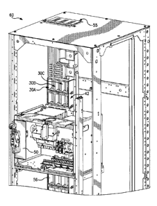
[0026] Figure 1 is a front perspective view from the right side, of a motor
control
center (MCC) cabinet 60 into which has been inserted a motor control unit 50
for
connection to three vertical bus bar phases 54A, 54B, and 54C (shown in
Figures 2 and 3)
via a front portion 30A, 30B, and 30C of three arc attenuating boxes A, B, and
C (shown
in Figure 7) supported in the MCC cabinet 60 by a front bus frame comprising a
vertical
support 42. Each of the front portions 30A, 30B, and 30C of the three arc
attenuating
boxes A, B, and C forms part of a chimney 55 along the respective three
vertical bus bar
phases 54A, 54B, and 54C, to provide directed venting of arc flash energy and
gases out
of the MCC cabinet 60. The motor control unit 50 is not normally connected to
the bus
bars when the unit is initially racked into the MCC cabinet 60. The motor
control unit has
a handle-cam mechanism (not shown) to rack-in the unit into the MCC cabinet,
which
mechanically locks the motor control unit into place in the MCC cabinet. The
operator
must then actuate a separate connect/disconnect handle on the front of the
motor control
unit, to advance movable female connectors, which can be clip-like conductive
structures
of the motor control unit, to electrically connect them to the bus bars.
[0027] Figure 2 is a front perspective view from the left side, of the
motor control
unit 50 in a connected position to the vertical bus bar phases 54A, 548, and
54C, via the
front portions 30A, 30B, and 30C of the three arc attenuating boxes A, B, and
C (shown
in Figure 7). The figure shows the vertical support 42, a horizontal support
44, and a rear
bus frame 51 in the motor control center cabinet 60 (not shown). An exterior
face of a
rear wall of the motor control unit 50 (shown in Figure 8) is configured to be
located
adjacent to the vertical bus bar phases 54A, 54B, and 54C when the motor
control unit 50
has been inserted into the MCC cabinet 60. Referring also to Figure 8,
connector
assemblies of a circuit breaker in the motor control unit 50, are connected to
the vertical
bus bar phases 54A, 54B, and 54C. A connector assembly is comprised of a
female
connector, for example 52A (collectively 52A, 52B, 52C), and one or both of a
connector
-7-
CA 02912085 2015-11-13
protector, e.g. 53A, surrounding the female connector 52A, and a fixed shroud
57A
surrounding the connector protector 53A. In other embodiments, the connector
assembly
may be solely the connector, such as the female connector. Each front portion
30A, 30B,
and 30C of the arc attenuating box A, B, and C fits over a free end of an
individual,
vertical bus bar phase 54A, 54B, 54C at a point of electrical connection
between motor
control unit 50 and the vertical bus bar.
[0028] Figure 3 is an exploded, front perspective view from the right side,
of a
portion of the motor control center (MCC) cabinet 60 of Figure 1, showing a
front bus
frame comprising two front vertical supports 42 and several horizontal
supports 44. In an
example embodiment, a front portion 30A, 30B, and 30C of three arc attenuating
boxes
A, B, and C (shown in Figure 7), may be grouped together and molded together
as a
unitary front cover 56, shown also in Figure 4 and Figure 7. The front cover
56 is
supported by vertically adjacent horizontal supports 44. The front portion
30A, 30B, and
30C of the three arc attenuating boxes A, B, and C fits over the free end of
the respective
vertical bus bar phases 54A, 54B, and 54C.
[0029] A rear portion 30A', 30B', and 30C' of three arc attenuating boxes
A, B,
and C may be grouped together and molded together as a unitary rear cover 56'
(shown in
Figure 7). The rear cover 56' is supported by the rear bus frame 51. The rear
portion
30A', 30B', and 30C' of the three arc attenuating boxes A, B, and C, fits over
a rear side
of the respective vertical bus bar phases 54A, 54B, and 54C.
[0030] The unitary front cover 56 and the unitary rear cover 56' are
snapped
together or otherwise securely joined, so that three snapped-together arc
attenuating boxes
A, B, and C are formed, as shown in Figure 6 and Figure 7. A first snapped-
together arc
attenuating box A is formed by snapping together the front portion 30A with
the rear
portion 30A', surrounding an individual, vertical bus bar phase 54A. A second
snapped-
together arc attenuating box B is formed by snapping together the front
portion 30B with
the rear portion 3013', surrounding an individual, vertical bus bar phase 54B.
A third
snapped-together arc attenuating box C is formed by snapping together the
front portion
30C with the rear portion 30C', surrounding an individual, vertical bus bar
phase 54C.
-8-
CA 02912085 2015-11-13
Each arc attenuating box A, B, and C surrounds the vertical bus bar phase at a
point of
electrical connection between motor control unit 50 and the vertical bus bar.
[0031] In the exploded view of Figure 3, the independently moveable, box-
shaped
shutters 64A, 64B, and 64C are shown aligned with the front portion and the
rear portion
of the respective arc attenuating boxes A, B, and C, to slide horizontally
within the
respective snapped-together arc attenuating boxes A, B, and C, as shown for
example in
Figure 7, for shutter 64C and arc attenuating box C.
100321 An example arc attenuating box A, shown in Figure 7, will surround a
first
phase vertical bus bar phase 54A (Fig. 2), and is configured to provide a
physical barrier
to arc flash energy and gases intruding into an adjacent arc attenuating box,
for example
box B (Fig 7), which will surround an adjacent second phase bus bar 54B (Fig.
2). For
example, side 56B of the arc attenuating box A, shown in Figure 7, helps
separate and
sequester the vertical bus bar first phase 54A and also forms a side wall of
the adjacent
box B. Each arc attenuating box A, B, and C is open at its top and bottom (see
e.g. Figs
6-7) to form a chimney 55A-55C along the respective vertical bus bar phases
54A, 54B,
54C, to provide directed venting of arc flash energy and gases out of the MCC
cabinet 60
(Fig. 1).
[00331 The motor control center may have additional rows of arc attenuating
boxes, e.g. stacked vertically for the various MCU spaces, or "buckets", with
each arc
attenuating box surrounding an individual one of the vertical bus bar phases
54A, 54B,
54C. Each arc attenuating box in the additional rows may be open at its top
and bottom to
form a chimney along a respective vertical bus bar phase, the chimney being
aligned with
the chimney of an arc attenuating box of other rows of arc attenuating boxes,
to provide
directed venting of arc flash energy and gases out of the motor control
center.
[0034] Figure 4 is a front perspective view from the right side, of the
vertical
support 42 holding the front portion 30A, 30B, and 30C of a row of the three
arc
attenuating boxes A, B, and C (Figure 7) grouped together at a front cover 56
for the bus
bars 54A, 54B, and 54C (Fig. 6). The independently moveable, box-shaped
shutters 64A,
64B, and 64C are shown in a closed position. The shutter assembly includes an
insulator
cap 62A, 62B, and 62C on a free end of the respective vertical bus bar phases
54A, 54B,
-9-
CA 02912085 2015-11-13
and 54C. The independently moveable, box-shaped shutters 64A, 64B, and 64C are
composed of an insulator material. The independently moveable, box-shaped
shutters
64A, 64B, and 64C slide horizontally within the arc attenuating boxes A, B,
and C. The
box-shaped shutters 64A, 64B, and 64C are configured to slide along the
respective
vertical bus bar phases 54A, MB, and 54C away from the insulator caps 62A,
6213, and
62C, in response to a force applied by a leading edge of a connector assembly
for the
motor control unit 50 (shown in Figure 8), when the motor control unit 50 is
being
connected to the vertical bus bars. The main body of each box-shaped shutter
64A, 64B,
and 64C has an opening, for example 65C of Fig. 7, through which the
respective vertical
bus bar phase 54A, 54B, and 54C passes when the motor control unit 50 is
connected to
the vertical bus bar.
[0035] Figure 5A is a front perspective view from the left side, of an
independently moveable, box-shaped shutter 64A, 64B, and 64C (shown as 64),
showing
the opening 65 through which the respective vertical bus bar phase passes when
the motor
control unit 50 is connected to the vertical bus bar. The figure shows the
opening or
chimney 55' that is open top to bottom in the box-shaped shutter 64. The
opening or
chimney 55' of the box-shaped shutter 64 aligns with the top to bottom opening
55 in the
arc attenuating box A, B, or C, in both the connected and disconnected
positions of the
motor control unit 50, as part of a chimney formed along each vertical bus
bar.
[0036] Figure 5B is a rear perspective view from the left side, of the
independently moveable, box-shaped shutter of Figure 5A, showing a forward-
biasing
spring 66 on the rear of the box-shaped shutter 64A, 64B, and 64C (shown as
64),
wherein the box-shaped shutter 64 slides horizontally along the vertical bus
54, in
response to a force applied by the spring 66, when the motor control unit 50
is
disconnected from the vertical bus bar.
[0037] Figure 6 is a front perspective view from the top, right side of a
front cover
56 of the front portions 30A, 30B, and 30C of the three arc attenuating boxes
A, B, and C
-10-
CA 02912085 2015-11-13
(shown in Figure 7). The front cover 56 is shown snapped together with the
rear cover
56' of the rear portions 30A', 30B', and 30C' (shown in Figure 7) of the three
arc
attenuating boxes A, B, and C. The rear cover 56' is mounted in the rear bus
frame 51 in
the motor control center cabinet (not shown). In the figure, female connectors
52A, 52B,
52C are placed in progressive states of connection to the bus bars for
explanatory
purposes, but will be understood to move as a unit and be in the same state of
connection
during actual operation. The arc attenuating box A surrounds the vertical bus
bar phase
54A. The arc attenuating box B surrounds the vertical bus bar phase 54B. The
arc
attenuating box C surrounds the vertical bus bar phase 54C. The insulator cap
62A, 62B,
and 62C is shown covering the free, front end of each respective bus bar phase
54A, 54B,
and 54C. Each independently moveable, box-shaped shutter 64A, 64B, and 64C is
located around a respective bus bar phase 54A, 54B, and 54C, and within the
arc
attenuating boxes A, B, and C that also surround each respective bus bar
phase. The
shutter assemblies comprising the independently moveable, box-shaped shutters
64A,
64B, and 64C and respective insulator caps 62A, 62B, and 62C, prevent access
to the
respective bus bars 54A, 54B, and 54C when the motor control unit 50 is in the
disconnected position, and allow access to the respective bus bars 54A, 54B,
and 54C
when the motor control unit 50 is in the connected position of Figure 2.
[0038] Figure 7 shows a row of front portions 30A, 30B, and 30C of three
arc
attenuating boxes A, B, and C, the front portions 30A, 30B, and 30C being
grouped
together as a first front cover 56. Each front portion 30A, 30B, and 30C of
the first arc
attenuating boxes is configured to fit over a free end of a respective one of
three vertical
bus bar phases 54A, 54B, and 54C shown in Figure 6.
[0039] The figure also shows a row of rear portions 30A', 30B', and 30C' of
the
three arc attenuating boxes A, B, and C being grouped together as a rear cover
56'. Each
rear portion 30A', 30B', and 30C' of the arc attenuating boxes is configured
to fit over a
rear end opposite to the free end of a respective one of the plurality of
vertical bus bar
phases 54A, 54B, and 54C shown in Figure 6.
[0040] The front cover 56 and the rear cover 56' are configured to snap
together,
with the front portion 30A, 30B, and 30C of the arc attenuating boxes fitting
over the free
-11-
CA 02912085 2015-11-13
end of the vertical bus bar phases and the rear portion 30A', 30B', and 30C'
of the arc
attenuating boxes fitting over the rear end of the vertical bus bar phases,
each arc
attenuating box surrounding an individual vertical bus bar phase.
[0041] The front cover 56 has vertical wall sides 56A, 56B, 56C, and 56D
with a
rear-facing mating surface 71. The rear cover 56' has vertical wall sides
56A', 56B',
56C', and 56D' with a front-facing mating surface 72. The rear-facing mating
surface 71
of the front cover 56 is configured to mate and interlock with the front-
facing mating
surface 72 of the rear cover 56' to form the internal sides of the arc
attenuating boxes A,
B, and C.
[0042] The insulator caps, collectively 62, are positioned within the front
cover 56
and fit on the front, free end, of their respective bus bars 54, when
assembled. The
insulator caps 62A, 62B, and 62C may be formed as an integral part of the
front cover 56.
Alternately, the insulator cap may be a coating of insulator material on the
free end of the
respective vertical bus bars.
[0043] Figure 8 is a top, rear perspective view from the right, of the
motor control
unit 50, showing the female connectors 52A, 52B, and 52C, sometimes called
"clusters",
with their leading edges projecting out in a position to apply a force on the
respective
shutter 64A, 64B, and 64C to slide the shutter along the bus bar away from the
insulator
cap, when in the connected position. In an alternate embodiment, the connector
assembly
may be a female connector and one or both of a connector protector 53A-53C
surrounding the female connector, and a fixed shroud 57A-57C surrounding the
connector
protector. In an alternate embodiment (not shown), a leading edge of a
connector
protector surrounding the female connector, applies the force on the shutter
to slide the
shutter along the vertical bus bar away from the insulator cap, when in the
connected
position.
[0044] Although specific example embodiments of the invention have been
disclosed, persons of skill in the art will appreciate that changes may be
made to the
details described for the specific example embodiments, without departing from
the spirit
and the scope of the invention.
-12-