Note: Descriptions are shown in the official language in which they were submitted.
CA 02912182 2016-12-16
SYSTEM AND METHODS FOR ANOMALOUS CATHODE EVENT CONTROL WITH
CONTROL OF WELDING CURRENT ACCORDING TO 'THE STATE DETECTED VOLTAGE
BACKGROUND
[0002] The invention relates generally to welding systems, and particularly
to
control of welding systems for gas-metal arc welding (GMAW).
[0003] Arc welding systems generally include a power source that applies
electrical current to an electrode so as to pass an arc between the electrode
and a work
piece, thereby heating the electrode and work piece to create a weld. In many
systems, the electrode consists of a wire that is advanced through a welding
torch.
During the welding process, portions of the molten wire are deposited on the
work
piece via the arc. Unfortunately, instabilities of the arc affect the
application of the
electrode to the weld.
BRIEF DESCRIPTION
[0004] Certain aspects commensurate in scope with the originally claimed
invention are set forth below. It should be understood that these aspects are
presented
merely to provide the reader with a brief summary of certain forms the
invention
might take and that these aspects are not intended to limit the scope of the
invention.
Indeed, the invention may encompass a variety of aspects that may not be set
forth
below.
[0005] In one embodiment, a welding system includes a power source and control
circuitry coupled to the power source. The power source is configured to
supply weld
CA 02912182 2016-12-16
power to a torch in a plurality of pulse periods, wherein each pulse period
includes a
peak phase and a background phase. The weld power includes a weld current and
a
weld voltage. The control circuitry is configured to control the weld current
to a
background current when a voltage value of the weld voltage is greater than a
detect
voltage in the background phase.
[0006] In another embodiment, a method of operating a welding system
includes
supplying a weld current and a weld voltage to an electrode via a plurality of
pulse
periods, where each pulse period of the plurality of pulse periods includes a
background phase and a peak phase. The method also includes detecting the
occurrence of an anomalous cathode event during the background phase of a
first pulse
period of the plurality of pulse periods based at least in part on when a
voltage value of
the weld voltage is greater than a detect voltage. The method also includes
controlling
the weld current to a desired current during a portion of the anomalous
cathode event.
The portion includes an interval of the background phase of the first pulse
period, and
the weld current is controlled independent of the weld voltage during the
portion of the
anomalous cathode event.
[0007] In another embodiment, a method of operating a welding system
includes
supplying a weld current at a peak current value and a weld voltage at a peak
voltage
value to a welding wire in a first peak phase of a first pulse period. The
weld current
is indirectly controlled based at least in part on the weld voltage during the
first peak
phase. The method also includes supplying the weld current at a background
current
value and the weld voltage at a background voltage value to the welding wire
at a first
portion of a background phase of the first pulse period. The method also
includes
controlling the weld current to the background current value independent of
the weld
voltage during a second portion of the background phase of the first pulse
period,
wherein the second portion of the background phase includes an anomalous
cathode
event.
[0007A] In a further embodiment there is provided, a welding system including
a
power source configured to supply weld power to a torch in a plurality of
pulse
2
CA 02912182 2016-12-16
periods. Each pulse period of the plurality of pulse periods includes a peak
phase and a
background phase, and the weld power includes a weld current and a weld
voltage; and
control circuitry coupled to the power source. The control circuitry is
configured to
control the weld current to a background current when a voltage value of the
weld
voltage is greater than a detect voltage in the background phase.
[0007B] In another embodiment there is provided, a method including the steps
of
supplying a weld current at a peak current value and a weld voltage at a peak
voltage
value to an electrode in a first peak phase of a first pulse period. The weld
current is
indirectly controlled based at least in part on the weld voltage during the
first peak
phase; supplying the weld current at a background current value and the weld
voltage
at a background voltage to the electrode at a first portion of a background
phase of the
first pulse period. Controlling the weld current to the background current
value
independent of the weld voltage during a second portion of the background
phase of
the first pulse period. The second portion of the background phase includes an
anomalous cathode event.
2a
CA 02912182 2015-11-10
WO 2014/200825
PCT/US2014/041201
DRAWINGS
[0008] These and other features, aspects, and advantages of the present
invention
will become better understood when the following detailed description is read
with
reference to the accompanying drawings in which like characters represent like
parts
throughout the drawings, wherein:
[0009] FIG. 1 is an embodiment of a MIG welding system with a power source
and a wire feeder;
[0010] FIG. 2 is a chart illustrating pulsed voltage and current waveforms
during
anomalous cathode events;
[0011] FIG. 3 is a chart illustrating pulsed voltage and current waveforms
with a
controlled current waveform during anomalous cathode events; and
[0012] FIG. 4 is a flow chart illustrating steps to control current during
an
anomalous cathode event.
DETAILED DESCRIPTION
[0013] One or more specific embodiments of the present invention will be
described below. In an effort to provide a concise description of these
embodiments,
all features of an actual implementation may not be described in the
specification. It
should be appreciated that in the development of any such actual
implementation, as
in any engineering or design project, numerous implementation-specific
decisions
must be made to achieve the developers' specific goals, such as compliance
with
system-related and business-related constraints, which may vary from one
implementation to another. Moreover, it should be appreciated that such a
development effort might be complex and time consuming, but would nevertheless
be
a routine undertaking of design, fabrication, and manufacture for those of
ordinary
skill having the benefit of this disclosure.
3
CA 02912182 2015-11-10
WO 2014/200825
PCT/US2014/041201
[0014] Turning
now to the drawings, and referring first to FIG. 1, an exemplary
welding system 10 is illustrated as including a power source 12 coupled to a
wire
feeder 14. In the illustrated embodiment the power source 12 is separate from
the
wire feeder 14, such that the wire feeder 14 may be positioned at some
distance from
the power source 12 near a welding location. However, it should be understood
that
the wire feeder 14, in some implementations, may be integral with the power
source
12. The power source 12 may supply weld power to a torch 16 through the wire
feeder 14, or the power source 12 may supply weld power directly to the torch
16.
The wire feeder 14 supplies a wire electrode 18 (e.g., solid wire, cored wire,
coated
wire) to the torch 16. A gas supply 20, which may be integral with or separate
from
the power source 12, supplies a gas (e.g., CO2, argon) to the torch 16. An
operator
may engage a trigger 22 of the torch 16 to initiate an arc 24 between the
electrode 18
and a work piece 26. In some embodiments, the welding system 10 may be
triggered
by an automation interface, including, but not limited to a programmable logic
controller (PLC) or robot controller. The welding system 10 is designed to
provide
welding wire (e.g., electrode 18), weld power, and shielding gas to the
welding torch
16. As will be appreciated by those skilled in the art, the welding torch 16
may be of
many different types, and may facilitate use of various combinations of
electrodes 18
and gases.
[0015] The
welding system 10 may receive data settings from the operator via an
operator interface 28 provided on the power source 12. The operator interface
28 may
be incorporated into a faceplate of the power source 12, and may allow for
selection
of settings such as the weld process (e.g., stick, TIG, MIG), the type of wire
to be
used, voltage and current settings, transfer mode (e.g., short circuit, pulse,
spray,
pulse), and so forth. In particular, the welding system 10 allows for MIG
welding
(e.g., pulsed MIG, spray, short circuit, Regulated Metal Deposition (i.e., RMD
0))
with electrodes 18 (e.g., welding wires) of various materials, such as steel
or
aluminum, to be channeled through the torch 16. The weld
settings are
communicated to control circuitry 30 within the power source 12. Additionally,
or in
the alternative, the control circuitry 30 is within the wire feeder 14, the
torch 16, the
gas supply 20, or another component of the welding system 10.
4
CA 02912182 2015-11-10
WO 2014/200825
PCT/US2014/041201
[0016] The control circuitry 30, described in greater detail below,
operates to
control generation of welding power output that is applied to the electrode 18
by
power conversion circuitry 32 for carrying out the desired welding operation.
In some
embodiments, the control circuitry 30 may be adapted to regulate a pulsed MIG
welding regime that may have aspects of short circuit transfer and/or of spray
transfer
of molten metal from the welding wire to a molten weld pool of a progressing
weld.
As described more fully below, such transfer modes may be controlled during
operation by adjusting operating parameters of current and voltage pulses for
arcs 24
developed between the electrode 18 and the work piece 26. "Pulsed welding" or
"pulsed MIG welding" refers to techniques in which a pulsed power waveform is
generated, such as to control deposition of metal droplets into the
progressing weld
pool. In a particular embodiment of the invention, a pulsed welding regime may
be
implemented in which the weld current of the arc is controlled to a desired
current
during anomalous cathode events that affect the weld voltage. That is, the
weld
current may be controlled independent of the weld voltage during the anomalous
cathode event.
[0017] The control circuitry 30 is coupled to the power conversion
circuitry 32,
which supplies the weld power (e.g., pulsed waveform) that is applied to the
electrode
18 at the torch 16. The power conversion circuitry 32 is coupled to a source
of
electrical power as indicated by arrow 34. The power applied to the power
conversion circuitry 32 may originate in the power grid, although other
sources of
power may also be used, such as power generated by an engine-driven generator,
batteries, fuel cells or other alternative sources. Components of the power
conversion
circuitry 32 may include choppers, boost converters, buck converters,
inverters, and
so forth.
[0018] The control circuitry 30 controls the current and/or the voltage of
the weld
power supplied to the torch 16. The control circuitry 30 may monitor the
current
and/or voltage of the arc 24 based at least in part on one or more sensors 36
within the
wire feeder 14 or torch 16. In some embodiments, a processor 38 of the control
circuitry 30 determines and/or controls the arc length or electrode extension
based at
least in part on feedback from sensors 36. The arc length is defined herein as
the
CA 02912182 2015-11-10
WO 2014/200825
PCT/US2014/041201
length of the arc between the electrode 18 and the work piece 26. The
processor 38
determines and/or controls the arc length or electrode extension utilizing
data (e.g.,
algorithms, instructions, operating points) stored in a memory 40. The data
stored in
the memory 40 may be received via the operator interface 28, a network
connection,
or preloaded prior to assembly of the control circuitry 30. Operation of the
power
source 12 may be controlled in one or more modes, such as a constant voltage
(CV)
regulation mode in which the control circuitry 30 controls the weld voltage to
be
substantially constant while varying the weld current during a welding
operation.
That is, the weld current may be based at least in part on the weld voltage.
Additionally, or in the alternative, the power source 12 may be controlled in
a current
control mode in which the weld current is controlled independent of the weld
voltage.
In some embodiments, the power source 12 is controlled to operate in a
constant
current (CC) mode where the control circuitry 30 controls the weld current to
be
substantially constant while varying the weld voltage during a welding
operation.
[0019] FIG. 2 is an embodiment of weld voltage 50 and weld current 52
waveforms of a pulsed welding process. The weld voltage 50 waveform and the
weld
current 52 waveform over pulse periods A, B, and C are shown. During a peak
phase
54 of each pulse period, the control circuitry increases the weld voltage 50
supplied to
the electrode, forming and/or separating a molten ball from the tip of the
electrode to
be deposited on the work piece or weld pool. The weld voltage 50 increases
from a
background voltage level 60 to approximately a peak voltage 62, thereby
increasing
the weld current 52 from a background current level 56 to approximately a peak
current 58. The weld voltage 50 and weld current 52 may decrease from peak
levels
to a background phase 64. In other words, the weld current 52 is indirectly
controlled
during the peak phase 54 based at least in part on the weld voltage 50. In
some
embodiments, during the background phase 64, the molten ball may briefly join
the
electrode to the weld pool in a short circuit event 66 that decreases the weld
voltage
50. In some embodiments, the molten ball is deposited from the electrode to
the weld
pool without the short circuit event 66. In the background phase 64, the
control
circuitry may generally maintain the weld voltage 50 at the background voltage
60,
and the weld current 52 may remain at approximately the background current 56
to
6
CA 02912182 2015-11-10
WO 2014/200825
PCT/US2014/041201
maintain an arc between the electrode and the work piece. The weld power via
the
weld current 52 and the weld voltage 50 may begin forming another molten ball
at the
tip of the electrode during the background phase 64. Accordingly, each pulse
period
may generally be described by a peak phase 54 during which the weld voltage 50
is
increased and a background phase 64 during which the weld current 52 is
desired to
be at a substantially constant current value.
[0020] As discussed herein, the term pulse period is not intended to be
limited to a
cycle (e.g., peak phase 54, background phase 64) of the weld voltage 50 and
weld
current 52 waveforms for only a pulsed MIG welding regime. As may be
appreciated,
the weld voltage 50 and the weld current 52 of various MIG welding processes
(e.g.,
pulsed MIG, short circuit, spray, and RMD) are cyclical. That is, each cycle
of a MIG
process includes one or more peak phases 54 with an elevated weld voltage 50
and
one or more background phases 64 with a desired substantially constant weld
current
52. For example, a peak phase 54 may include the pinch, clear, and/or ball
stages of
the RMD process, and the background phase 64 may include the blink,
background,
pre-short, and/or wet stages of RMD process. As utilized herein, the term
pulse
period, may include, but is not limited to, a cycle (e.g., one or more
sequences of a
peak phase 54 and a background phase 64) of a pulsed MIG welding regime, a
short
circuit process, a spray process, or an RMD process, or any combination
thereof.
[0021] As may be appreciated, the processor 38 of the control circuitry 30
may
control the weld voltage 50 and weld current 52 values within different ranges
based
at least in part on the desired weld parameters input via the operator
interface, the
electrode, the feed rate of the electrode, the gas, the work piece, or any
combination
thereof For example, the background current level 56 may be between
approximately
25 to 250 amps. The peak current 58 may be between approximately 300 to 700
amps. In some embodiments, the background voltage level 60 may be between
approximately 15 to 25 volts, and the peak voltage 62 may be between
approximately
25 to 40 volts.
[0022] The weld voltage 50 and weld current 52 waveforms of a pulsed
process
may generally resemble pulse period A. However, anomalous cathode events 68
may
7
CA 02912182 2015-11-10
WO 2014/200825
PCT/US2014/041201
begin in the background phase 64 of some pulse periods and persist for various
durations. Some anomalous cathode events 68 may persist only during a portion
of
the background phase 64, and other anomalous cathode events 68 may persist
through
the background phase 64 and into a portion of the peak phase 54. The anomalous
cathode events 68 may affect the weld voltage 50 and weld current 52 as shown
in
pulse periods B and C. The anomalous cathode events 68 of pulse periods B and
C
illustrate the weld voltage 50 and weld current 52 waveforms without
application of
the control algorithm by the control circuitry as described below. After the
peak
phase 54, the weld voltage 50 may rise in the anomalous cathode event 68. The
unmitigated anomalous cathode event 68 affects the arc between the electrode
and the
work piece by restricting or narrowing the arc. That is, the arc during the
anomalous
cathode event 68 of pulse period B may be relatively narrow compared to the
relatively wide and/or bell shaped arc during the background phase 64 of pulse
period
A. Without the control algorithm described below, the weld current 52, which
is
controlled based on the weld voltage 50, may decrease to low current level 70
while
the control circuitry attempts to maintain the weld voltage 50 at the desired
background voltage 60. Effects of the unmitigated anomalous cathode event 68
on
the weld process may include, but are not limited to, increased occurrence of
spatter,
inconsistent ball transfer, irregular weld appearance, decreased arc
stability, or an
increased probability of subsequent anomalous cathode events 68, or any
combination
thereof
[0023] The processor 38 of the control circuitry 30 may determine the
occurrence
of anomalous cathode events and control the weld current 52 with the control
algorithm to decrease the effects on the weld process. FIG. 3 illustrates an
embodiment of weld voltage 50 and weld current 52 waveforms of the pulsed
process
over pulse periods D, E, and F of a welding process. Pulse periods E, F, and G
may
have substantially uniform pulse durations. The control circuitry monitors the
weld
voltage 50 to detect the start (e.g., rising weld voltage 50) of an anomalous
cathode
event 80. In some embodiments, the control circuitry monitors the weld voltage
50
for the start of the anomalous cathode event 80 only during the background
phase 64
and/or not during the peak phase 54. The processor 38 of the control circuitry
30 may
8
CA 02912182 2015-11-10
WO 2014/200825
PCT/US2014/041201
compare the weld voltage 50 to a detect voltage (e.g., Vdetect), which may be
exceeded
at the onset of and during an anomalous cathode event 80. When the weld
voltage 50
is approximately greater than the detect voltage (e.g., during the anomalous
cathode
event 80), the processor 38 of the control circuitry 30 may control the weld
current 52
based at least in part on a control algorithm stored in the memory 40, rather
than
controlling the weld current 52 based on the weld voltage 50. For example, the
control algorithm may direct the control circuitry to control the weld current
52 to
approximately the background current 56 or other desired current value during
the
anomalous cathode event 80 despite deviations of the weld voltage 50 from the
background voltage 60. A duration of the anomalous cathode event 80 may
include,
but is not limited to, an interval (e.g., portion) of the background phase 64
less than
approximately 10, 25, 50, or 75 percent or more of the background phase 64.
The
control algorithm may direct the processor 38 of the control circuitry 30 to
control the
weld current 52 during anomalous cathode events 80 in pulse periods E and F to
approximately the same value during the background phase 64 as during pulse
period
D, thereby controlling the weld current 52 to be substantially unaffected by
the rising
weld voltage 50 during the anomalous cathode event 80. The control algorithm
stored
in the memory 40 may direct the processor 38 of the control circuitry 30 to
control the
weld current 52 to be independent of the weld voltage 50 during at least a
portion of
the anomalous cathode event 80. In some embodiments, the control algorithm
directs
the processor 38 of the control circuitry 30 to substantially maintain the
weld current
52 at the background current 56 during the anomalous cathode event 80 when the
weld voltage 50 is not near the background voltage 60.
[0024] The anomalous cathode event 80 may end when the weld voltage 50 drops
below approximately an end voltage (e.g., Vend). If the anomalous cathode
event 80
ends during the background phase 64, the control algorithm may direct the
processor
38 of the control circuitry 30 to maintain the weld current 52 at the
background
current 56 or another predetermined dynamic current value based on the
operating
point of the electrode for the remainder of the background phase 64. In some
embodiments, the control algorithm may direct the processor 38 of the control
circuitry 30 to resume the voltage regulation method (e.g., constant voltage)
in place
9
CA 02912182 2015-11-10
WO 2014/200825
PCT/US2014/041201
prior to the anomalous cathode event 80. If the anomalous cathode event 80
ends
during another phase (e.g., peak phase 54), the control algorithm may direct
the
processor 38 of the control circuitry 30 to adjust the weld current 52 to an
appropriate
current level. For example, if the anomalous cathode event 80 ends in a peak
phase
54, the control algorithm directs the processor 38 of the control circuitry 30
to control
the weld current 52 to an appropriate current level between the background
current 56
and the peak current level 58, thereby enabling the weld current waveform 52
to
substantially maintain uniformity of the current waveform among pulse periods.
For
example, the background phase 64 may have the same background duration (e.g.,
approximately 1 to 20, 2 to 15, or 3 to 10 milliseconds) for each pulse
period, and the
peak phase 54 may have the same peak duration (e.g., approximately 0.5 to 5,
0.75 to
4, or 1 to 3 milliseconds). The control algorithm enables the processor 38 of
the
control circuitry 30 to control the weld current 52 during the anomalous
cathode event
80 outside of a typical regulation mode (e.g., constant voltage regulation),
thereby
reducing the occurrence of spatter, increasing the consistency of ball
transfer to the
weld pool, improving the appearance of the weld, increasing arc stability, or
decreasing probability of subsequent anomalous cathode events 80, or any
combination thereof
[0025] The detect voltage (Vdetect) and the end voltage (Vend) may be based
at least
in part on the electrode properties, the gas utilized during the welding
operation, the
operating point of the electrode, and/or the operating point of the shielding
gas. The
operating point of the electrode and the operating point of the shielding gas
may be
empirically determined and stored in the memory 40 of the control circuitry
30. For
example, the operating points may be stored in the memory 40 with the control
algorithm. In some embodiments, Vdetect and/or Vend may be greater than the
background voltage 60, and less than the peak voltage 62. For example, Vdetect
may
be between approximately 25 to 35 V, and Vend may be between approximately 15
to
25 V. Voltage values for Vdetect may be approximately 1, 2, 3, 4, 5, 6, 7, 8,
9, or 10 V
or more than the background voltage 60. Additionally, or in the alternative,
Vdetect
may be approximately 1, 2, 3, 5, 10, or 20 percent greater than the background
voltage
60. In some embodiments, values for Vdetect and/or Vend for various
combinations of
CA 02912182 2015-11-10
WO 2014/200825
PCT/US2014/041201
electrodes and gases may be loaded from a memory into the control circuitry
prior to
or during a welding process. The values for Vdetect and/or Vend may be
simulated
voltages based at least in part on the current feedback, electrode extension,
or arc
length, or any combination thereof. The weld voltage 50 during a non-anomalous
cathode pulse periods (e.g., pulse period D) may have voltage components
across the
electrode (e.g., VEE), the arc (e.g., Vare Vanede, Vcathode), and the work
piece. In some
embodiments, the simulated voltage may be based at least in part on a sum of
the
separately calculated voltage components of the weld voltage 50 during one or
more
non-anomalous cathode pulse periods. For example, the simulated voltage may be
based at least in part on feedback from a state observer (e.g., Kalman filter)
that
receives real-time feedback from at least one of the control circuitry, the
power
conversion circuitry, and the sensors. The processor 38 of the control
circuitry 30
may determine the electrode extension and/or arc length based at least in part
on
feedback from the sensors in the torch.
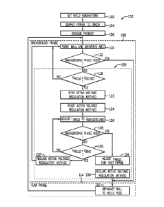
[0026] FIG. 4 illustrates an embodiment of a method 100 for operating the
welding
system and initiating the control algorithm described above. The operator may
set
(block 102) weld parameters for the welding operation via the operator
interface
and/or via coupling components (e.g., wire feeder, torch, gas supply) to the
power
source. Weld parameters may include, but are not limited to, the current,
voltage,
transfer mode, pulse duration, pulse frequency, work piece material,
electrode, and
supply, or any combination thereof The power source supplies (block 104) power
to
the torch, and the operator may engage (block 106) a trigger to initiate an
arc between
the electrode of the torch and the work piece. During a background phase
(block
108), the weld power supplied to the electrode via the torch forms (block 110)
a ball
and maintains the arc between the electrode and the work piece. In some
embodiments, the processor 38 of the control circuitry 30 may control the weld
current and weld voltage to substantially constant values during the
background
phase. After the processor 38 of the control circuitry 30 determines (node
112) that
the background phase is over (e.g., time t in background phase has exceeded a
background interval of the pulse period), the control circuitry 30 may
transition to the
peak phase (block 114). During the peak phase (block 114), the molten ball may
11
CA 02912182 2015-11-10
WO 2014/200825
PCT/US2014/041201
separate (block 116) from the electrode for deposit in the weld pool. The
control
circuitry 30 may control the weld current and weld voltage to increase during
the peak
phase. The background phase (block 108) and peak phase (block 114) may repeat
for
the duration of the weld process while the operator engages the trigger (block
106) or
automation interface engages the welding system. In some embodiments, the
processor 38 of the control circuitry 30 may control the weld current and weld
voltage
with additional phases between the repeated background and peak phases.
[0027] During the background phase (block 108), the processor 38 of the
control
circuitry 30 monitors the weld voltage. At node 118, the processor 38 of the
control
circuitry 30 compares the weld voltage to the voltage detect value (Vdetect)
to
determine if an anomalous cathode event is occurring. Vdetect may be
dynamically
determined and/or loaded from a memory of the control circuitry. If the weld
voltage
is greater than the voltage detect value, the processor 38 of the control
circuitry 30
utilizes the control algorithm 120 to mitigate effects of the anomalous
cathode event
on the weld process. In the control algorithm 120, the processor 38 of the
control
circuitry 30 stops (block 122) or suspends the active voltage regulation
method. For
example, the processor 38 of the control circuitry 30 may utilize a voltage
regulation
method (e.g., constant voltage method) to control the weld voltage and/or weld
current to maintain a desired arc length or electrode extension. In some
embodiments,
the processor 38 of the control circuitry 30 may reset (block 124) the active
voltage
regulation method, such as by clearing stored data (e.g., running average,
sensor
feedback) from the memory 40. Resetting the active voltage regulation method
may
increase the accuracy and/or reliability of the voltage regulation method,
thereby
increasing the stability of the arc. For example, the active voltage
regulation method
may utilize previously measured current and/or voltage measurements stored in
the
memory 40. The conditions of the arc (e.g., measured current and/or voltage)
during
the anomalous cathode event are different than during the background phase of
a non-
anomalous cathode event (e.g., pulse period D). Accordingly, the previously
measured current and/or voltage measurements stored in the memory 40 utilized
for
the active voltage regulation method are reset (block 124) to enable the
active voltage
regulation method to be resumed at block 132 without utilizing measured
current
12
CA 02912182 2015-11-10
WO 2014/200825
PCT/US2014/041201
and/or voltage measurements from the anomalous cathode event for the active
voltage
regulation method.
[0028] The control algorithm 120 directs the processor 38 of the control
circuitry
30 to adjust (block 126) the weld current to the desired background current, a
predetermined current value, or a dynamically determined current value. In
some
embodiments, the desired background current may be approximately the same as
the
background current during the prior background phase from the previous pulse
period.
The processor 38 of the control circuitry 30 may increase or decrease the weld
current
to the desired background current at a ramp rate (e.g., linear) based at least
in part on
the electrode, wire, or any combination thereof. The ramp rate may be stored
in the
memory 40 or otherwise determined within the control circuitry 30 during the
background phase. Additionally, or in the alternative, the ramp rate may be
empirically determined and stored in the memory 40 with the algorithm.
[0029] If the processor 38 of the control circuitry 30 determines (node
128) the
background phase is not over (e.g., time t in background phase has not
exceeded
background interval), then the processor 38 of the control circuitry 30
determines
(node 130) whether the weld voltage is less than the end voltage Vend. If the
weld
voltage is less than Vend, the control algorithm may determine that the
anomalous
cathode event has ended, and the control algorithm directs the processor 38 of
the
control circuitry 30 to resume (block 132) the active voltage regulation
method and
return to block 110. If the weld voltage is greater than Vend, the control
algorithm may
adjust (block 126) the weld current to the background current, and cycle
through
nodes 128 and 130 until the background phase ends or the weld voltage is less
than
Vend (e.g., anomalous cathode event ends). If the background phase ends while
the
weld voltage is greater than Vend, the control algorithm directs the control
circuitry to
adjust (block 134) the weld current for the next phase (e.g., peak phase 114)
and
resume (block 136) the active voltage regulation method. For example, if the
anomalous cathode event persists into the peak phase 114, the control
algorithm
directs the processor 38 of the control circuitry 30 to increase the weld
current to the
appropriate weld current to substantially correspond with prior peak weld
current
13
CA 02912182 2015-11-10
WO 2014/200825
PCT/US2014/041201
waveforms, thereby reducing the effect of the anomalous cathode event on the
peak
phase of the weld current.
[0030] While only certain features of the invention have been illustrated
and
described herein, many modifications and changes will occur to those skilled
in the
art. It is, therefore, to be understood that the appended claims are intended
to cover
all such modifications and changes as fall within the true spirit of the
invention.
14