Note: Descriptions are shown in the official language in which they were submitted.
CA 02912191 2015-11-09
WO 2015/021182 PCT/US2014/049981
IMAGE-BASED DIRECT NUMERICAL SIMULATION OF PETROPHYSICAL
PROPERTIES UNDER SIMULATED STRESS AND STRAIN CONDITIONS
* * * * *
BACKGROUND OF THE INVENTION
[0001] This disclosure relates generally to methods and systems for
analyzing
images of rock samples to determine petrophysical properties.
[0002] In hydrocarbon production, obtaining accurate subsurface
estimates of
petrophysical properties of the rock formations is important for the
assessment of
hydrocarbon volumes contained in the rock formations and for formulating a
strategy for
extracting the hydrocarbons from the rock formation. Traditionally, samples of
the rock
formation, such as from core samples or drilling cuttings, are subjected to
physical laboratory
tests to measure petrophysical properties such as permeability, porosity,
formation factor,
elastic moduli, and the like. As known in the art, some of these measurements
require long
time periods, extending over several months in some cases, depending on the
nature of the
rock itself The equipment used to make these measurements can also be quite
costly.
[0003] Often, petrophysical rock properties are measured in the
laboratory at
ambient environmental conditions, with the rock sample at room temperature and
surface
atmospheric pressure. However, the sub-surface environment of the rock in the
formation
can differ significantly from that of ambient laboratory conditions. For
example, the weight
of overburden sedimentation on formation rock, which increases with increasing
burial
depth, causes compaction of the formation rock, which is reflected in reduced
porosity and
permeability as compared with surface ambient conditions.
[0004] Subsurface rock formations are also subjected to changes in in situ
stress/strain conditions as a result of hydrocarbon development and
production. For instance,
the stress conditions at a point in a rock formation adjacent to a drilled
borehole will differ
from the original in situ stress conditions at that same point prior to
drilling. In addition, the
injection and extraction of pore fluids, as occurs in field production, sets
up changes in pore
fluid pressure from that prior to production, which also causes changes in in
situ stress
conditions. Different stress or strain conditions from these and other causes
can significantly
alter the petrophysical properties of rock relative to the same rock under
ambient conditions.
CA 02912191 2015-11-09
WO 2015/021182 PCT/US2014/049981
Of course, it is the subsurface petrophysical properties of the rock under its
in situ stress
conditions that are of most interest for purposes of appraisal, development,
and production
of the field.
[0005] To compensate for the effect of changes in in situ stress,
conventional
laboratory measurements of porosity, permeability, electrical conductivity,
and other
petrophysical properties can be physically measured in the laboratory under a
variety of
stress and strain conditions. It has been observed, however, that the
equipment and
technician time required to artificially apply these physical conditions in
the laboratory can
be prohibitively expensive, as compared with tests performed under room
ambient
conditions, and can also require significantly more time to carry out,
especially for
complicated rock types. Moreover, the range of laboratory-applied stress and
strain
conditions for the measurement of a particular petrophysical property is often
quite limited,
and may not accurately represent the in situ subsurface conditions.
[0006] Even if equipment for measuring rock properties under
confining stresses and
pressures is available, the estimation of petrophysical properties of a given
rock sample
under several different stress/strain conditions is often not possible,
because the
microstructure of the rock sample may be permanently deformed by one or more
of the
loading and unloading stress/strain cycles. This deformation may occur, for
instance, when
measuring petrophysical properties of a given rock sample initially under
hydrostatic stress
conditions (i.e., where the sample is subjected to uniform confining pressure)
and then
measuring the petrophysical properties of the same rock under uniaxial stress
conditions (i.e.,
where stress is applied in only a single direction, with no applied stress in
all other
directions). In that case, subsequent iterations of the measurement experiment
on the same
sample can result in a different petrophysical property value or other change
in physical
behavior that is not representative of the true stress/strain response of the
rock. The measured
petrophysical properties in the second and subsequent stress experiments may
thus differ
significantly from the true in situ values sought for those stress
experiments.
[0007] Because of the cost and time required to directly measure
petrophysical
properties, the technique of "direct numerical simulation" has been developed
for efficiently
estimating physical properties, such as porosity, absolute permeability,
relative permeability,
formation factor, elastic moduli, and the like of rock samples, including
samples from
difficult rock types such as tight gas sands or carbonates. According to this
approach, a
2
CA 02912191 2015-11-09
WO 2015/021182 PCT/US2014/049981
three-dimensional tomographic image of the rock sample is obtained, for
example by way
of a computer tomographic (CT) scan. Voxels in the three-dimensional image
volume are
"segmented" (e.g., by "thresholding" their brightness values or by another
approach) to
distinguish rock matrix from void space. Numerical simulation of fluid flow or
other
physical behavior such as elasticity or electrical conductivity is then
performed, from which
porosity, permeability (absolute and/or relative), elastic properties,
electrical properties, and
the like can be derived. A variety of numerical methods may be applied to
solve or
approximate the physical equations simulating the appropriate behavior. These
methods
include the Lattice-Boltzmann, finite element, finite difference, finite
volume numerical
methods and the like.
[0008] However, conventional direct numerical simulation is generally
limited to
rock samples under ambient stress/strain conditions, in that images obtained
by X-ray
tomographic images or other imaging techniques (e.g., FIBSEM) are generally
acquired
under ambient conditions. This is because the mechanical equipment required to
induce
stress/strain conditions are not routinely attached to imaging equipment, or
cannot feasibly
be so attached, due to the nature of either or both of the imaging and
mechanical devices. In
those cases in which imaging and mechanical testing have been combined, such
as by using
special sample holders that are transparent to X-ray tomography, such combined
experimental apparatus is highly specialized and extremely expensive, and may
involve
health and safety risks.
3
CA 02912191 2015-11-09
WO 2015/021182 PCT/US2014/049981
BRIEF SUMMARY OF THE INVENTION
[0009] Embodiments of this invention provide a system and method for
simulating
the subsurface conditions found in rock formations in the direct numerical
simulation of
physical processes from which petrophysical properties are derived.
[0010] Embodiments of this invention provide such a system and method that
substantially reduce the time and cost of traditional laboratory tests while
improving the
accuracy of those tests.
[0011] Embodiments of this invention provide such a system and method
that can be
implemented into conventional test and analysis equipment.
[0012] Other objects and advantages of embodiments of this invention will
be
apparent to those of ordinary skill in the art having reference to the
following specification
together with its drawings.
[0013] Embodiments of this invention may be implemented into an
analysis method,
system, and computer-readable medium storing executable program instructions
for
performing such analysis, based on a three-dimensional (3D) image of a rock
sample, in
which voxels or other portions of the 3D image corresponding to solid material
in the rock
sample are differentiated from voxels or other portions of the image
corresponding to pores
in that rock sample. An unstructured mesh overlaid onto the regions of the
image
corresponding to the solid material, followed by the numerical application of
a simulated
deformation, in the nature of stress, strain, force, displacement, or the
like, to that
unstructured mesh, for example by way of boundary conditions for a finite
element system
of equations. The simulated deformation can represent the subsurface
environment of the
rock sample at its original location in the formation. The effects of the
simulated
deformation, as represented by changes in the unstructured mesh, are intended
to emulate
deformations in the rock sample at the stress or strain levels in the sub-
surface. At least one
petrophysical property of the rock sample is then numerically or analytically
determined for
the unstructured mesh, as deformed by the simulated deformation.
4
CA 02912191 2015-11-09
WO 2015/021182 PCT/US2014/049981
BRIEF DESCRIPTION OF THE SEVERAL VIEWS OF THE DRAWING
[0014] Figure 1A is a generic block diagram that illustrates examples
of sources of
rock samples for a testing system constructed and operating according to
embodiments of
the invention.
[0015] Figure 1B is an electrical diagram, in block form, of a testing
system for
analyzing rock samples according to embodiments of the invention.
[0016] Figure 1C is an electrical diagram, in block form, of the
construction of a
computing device in the system of Figure 1B, according to embodiments of the
invention.
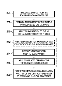
[0017] Figure 2 is a flow diagram illustrating a method of operating
a testing system
in analyzing rock samples, according to embodiments of the invention.
[0018] Figure 3A is a cross-sectional microphotograph of a rock
sample to which
embodiments of the invention may be applied.
[0019] Figure 3B through 3D are digital representations of the rock
sample of Figure
3A, to which embodiments of the invention may be applied.
[0020] Figure 3E is a digital plot illustrating an unstructured mesh as
applied to a
digital representation of a rock sample, before deformation.
[0021] Figure 3F is a digital plot illustrating the applied mesh of
Figure 3E under an
example of simulated stress field and corresponding pore space deformation,
according to
embodiments of the invention.
[0022] Figures 4A through 4F are digital representations of a rock sample,
to which
an embodiment that involves the analysis of grain contact regions is applied.
[0023] Figures 4G and 4H are plots illustrating the consideration of
grain contact
regions as described relative to the embodiment illustrated in Figures 4A
through 4F.
[0024] Figures 5A through 5D are flow diagrams illustrating the
method of Figure 2
according to each of several embodiments of the invention.
[0025] Figure 6 is a plot of porosity of a rock sample versus volume
change resulting
from displacement applied in one direction, as determined by application of an
embodiment
of the invention.
5
CA 02912191 2015-11-09
WO 2015/021182 PCT/US2014/049981
[0026] Figure 7 is a comparison of cross-sectional views resulting
from the
conversion of the unstructured grid after deformation by a simulated stress to
structured grids
of varying resolution, according to an embodiment of the invention
corresponding to Figure
5B.
[0027] Figure 8 is a plot of directional permeability of a rock sample
versus porosity,
as determined by application of an embodiment of the invention.
[0028] Figure 9 is a plot of formation factor of a rock sample versus
porosity, as
determined by application of an embodiment of the invention.
[0029] Figure 10 is a plot of resistivity index of a rock sample
versus water
saturation, as determined by application of an embodiment of the invention.
6
CA 02912191 2015-11-09
WO 2015/021182 PCT/US2014/049981
DETAILED DESCRIPTION OF THE INVENTION
[0030] This invention will be described in connection with its
embodiments, namely
as implemented into methods, systems, and corresponding software for analyzing
samples
of sub-surface formations by way of direct numerical simulation, with stress
and strains
numerically applied to those samples to investigate sub-surface effects of in
situ stress and
other conditions, as it is contemplated that this invention will be
particularly beneficial when
utilized for such results. However, it is contemplated that the invention can
be beneficially
applied to other applications, for example to replicate mechanical laboratory
testing, and to
determine other physical properties beyond those described in this
specification.
Accordingly, it is to be understood that the following description is provided
by way of
example only, and is not intended to limit the true scope of this invention as
claimed.
[0031] Embodiments of this invention are directed to systems and
methods for
numerical simulation of petrophysical properties under simulated stress/strain
arising from
the numerical application of stress, strain, force, or displacement boundary
conditions and
the numerical solution of appropriate constitutive equations for elasticity,
which relate
material stresses, strains, and other properties. More specifically, a testing
system performs
an image based direct numerical simulation of the petrophysical properties of
a sample of
rock, where the deformation is a result of the numerical application of
stress, strain, force,
or displacement boundary conditions and the numerical solution of the
appropriate
constitutive equations. Moreover, the application of specific stress, strain,
force, or
displacement boundary conditions may represent one or more subsurface
conditions, such as
the in situ stress conditions experienced by the rock in its original
subsurface location. Other
boundary conditions beyond stress, strain, force, and displacement, such as
those involving
rotations, rate-dependent displacements or strains, and the like, as well as
those formulations
that can be utilized to solve problems involving plasticity and other non-
linearities, among
others, may alternatively be used in connection with the disclosed
embodiments, and are
contemplated to be within the scope of the claims.
[0032] While certain embodiments will be described in this
specification with
reference to analysis of the effects of subsurface stress/strain conditions on
the petrophysical
properties of rock, it is contemplated that these embodiments can also be
utilized to explore
the general effect of different stress/strain paths on the petrophysical
properties of rock, even
though such paths may or may not correspond directly to subsurface
stress/strain conditions
7
CA 02912191 2015-11-09
WO 2015/021182 PCT/US2014/049981
or to the evolution of subsurface stress/strain conditions. In particular,
according to some
embodiments, gradual or incremental increases in stress or strain may be
numerically
applied, with petrophysical properties simulated at each incremental step.
These stress/strain
conditions may stand in direct analogy to traditional laboratory experiments
designed to test
the mechanical properties of rock, such experiments including hydrostatic
tests, uniaxial
compression, uniaxial strain, triaxial tests, and the like.
[0033] Figure lA illustrates, at a high level, the acquiring of rock
samples and their
analysis according to embodiments of this method. It is contemplated that
embodiments of
this invention will be especially beneficial in analyzing rock samples from
sub-surface
formations that are important in the production of oil and gas. As such,
Figure lA illustrates
environments 100 from which rock samples 104 to be analyzed by testing system
102 can
be obtained, according to various implementations. In these illustrated
examples, rock
samples 104 can be obtained from terrestrial drilling system 106 or from
marine (ocean, sea,
lake, etc.) drilling system 108, either of which is utilized to extract
resources such as
hydrocarbons (oil, natural gas, etc.), water, and the like. As is fundamental
in the art,
optimization of oil and gas production operations is largely influenced by the
structure and
physical properties of the rock formations into which terrestrial drilling
system 106 or marine
drilling system 108 is drilling or has drilled in the past.
[0034] It is contemplated, in embodiments of this invention, that the
manner in which
rock samples 104 are obtained, and the physical form of those samples, can
vary widely.
Examples of rock samples 104 useful in connection with embodiments of this
invention
include whole core samples, side wall core samples, outcrop samples, drill
cuttings, and
laboratory generated synthetic rock samples such as sand packs and cemented
packs.
[0035] As illustrated in Figure 1A, environment 100 includes testing
system 102 that
is configured to analyze images 128 of rock samples 104 in order to determine
the physical
properties of the corresponding sub-surface rock, such properties including
petrophysical
properties in the context of oil and gas exploration and production. Figure 1B
illustrates, in
a generic fashion, the constituent components of testing system 102 in
performing such
analysis.
[0036] In a general sense, testing system 102 includes imaging device 122
for
obtaining two-dimensional (2D) or three-dimensional (3D) images, as well as
other
representations, of rock samples 104, such images and representations
including details of
8
CA 02912191 2015-11-09
WO 2015/021182 PCT/US2014/049981
the internal structure of those rock samples 104. An example of imaging device
122 is a X-
ray computed tomography (CT) scanner, which as known in the art emits x-ray
radiation 124
that interacts with an object and measures the attenuation of that x-ray
radiation 124 by the
object in order to generate an image of its interior structure and
constituents. The particular
type, construction, or other attributes of CT scanner 122 can correspond to
that of any type
of x-ray device, such as a micro CT scanner, capable of producing an image
representative
of the internal structure of rock sample 104. In this example, imaging device
122 generates
one or more images 128 of rock sample 104, and forwards those images 128 to
computing
device 120.
[0037] The form of images 128 produced by imaging device 122 in this
example may
be in the form of a three-dimensional (3D) digital image volume consisting of
or generated
from a plurality of two-dimensional (2D) sections of rock sample 104. In this
case, each
image volume is partitioned into 3D regular elements called volume elements,
or more
commonly "voxels". In general, each voxel is cubic, having a side of equal
length in the x,
y, and z directions. Digital image volume 128 itself, on the other hand, may
contain different
numbers of voxels in the x, y, and z directions. Each voxel within a digital
volume has an
associated numeric value, or amplitude, that represents the relative material
properties of the
imaged sample at that location of the medium represented by the digital
volume. The range
of these numeric values, commonly known as the grayscale range, depends on the
type of
digital volume, the granularity of the values (e.g., 8 bit or 16 bit values),
and the like. For
example, 16 bit data values enable the voxels of an x-ray tomographic image
volume to have
amplitudes ranging from 0 to 65,536 with a granularity of 1.
[0038] As mentioned above, imaging device 122 forwards images 128 to
computing
device 120, which in the example of Figure 1B may be any type of conventional
computing
device, for example, a desktop computer or workstation, a laptop computer, a
server
computer, a tablet computer, and the like, and as such computing device 120
will include
hardware and software components typically found in a conventional computing
device. As
shown in Figure 1B, these hardware and software components of computing device
120
include testing tool 130 that is configured to analyze images 128 to determine
the
petrophysical properties of rock sample 104 under one or more simulated
deformation
conditions, including stress and strain conditions that may be encountered by
rock formations
in the sub-surface. In this regard, testing tool 130 may be implemented as
software,
9
CA 02912191 2015-11-09
WO 2015/021182 PCT/US2014/049981
hardware, or a combination of both, including the necessary and useful logic,
instructions,
routines, and algorithms for performing the functionality and processes
described in further
detail below. In a general sense, testing tool 130 is configured to analyze
image volume 128
of rock sample 104 to perform numerical simulation of the petrophysical
properties under
the simulated deformation representing subsurface conditions of rock
formations.
[0039] Figure 1C generically illustrates the architecture of
computing device 120 in
testing system 102 according to embodiments of the invention. In this example
architecture,
computing device 120 includes one or more processors 902, which may be of
varying core
configurations and clock frequencies as available in the industry. The memory
resources of
computing device 120 for storing data and also program instructions for
execution by the
one or more processors 902 include one or more memory devices 904 serving as a
main
memory during the operation of computing device 120, and one or more storage
devices 910,
for example realized as one or more of non-volatile solid-state memory,
magnetic or optical
disk drives, random access memory. One or more peripheral interfaces 906 are
provided for
coupling to corresponding peripheral devices such as displays, keyboards,
mice, touchpads,
touchscreens, printers, and the like. Network interfaces 908, which may be in
the form of
Ethernet adapters, wireless transceivers, or serial network components, are
provided to
facilitate communication between computing device 120 via one or more networks
such as
Ethernet, wireless Ethernet, Global System for Mobile Communications (GSM),
Enhanced
Data rates for GSM Evolution (EDGE), Universal Mobile Telecommunications
System
(UMTS), Worldwide Interoperability for Microwave Access (WiMAX), Long Term
Evolution (LTE), and the like. In this architecture, processors 902 are shown
as coupled to
components 904, 906, 908, 910 by way of a single bus; of course, a different
interconnection
architecture such as multiple, dedicated, buses and the like may be
incorporated within
computing device 120.
[0040] While illustrated as a single computing device, computing
device 120 can
include several computing devices cooperating together to provide the
functionality of a
computing device. Likewise, while illustrated as a physical device, computing
device 120
can also represent abstract computing devices such as virtual machines and
"cloud"
computing devices.
[0041] As shown in the example implementation of Figure 1C, computing
device
120 includes software programs 912 including one or more operating systems,
one or more
CA 02912191 2015-11-09
WO 2015/021182 PCT/US2014/049981
application programs, and the like. According to embodiments of the invention,
software
programs 912 include program instructions corresponding to testing tool 130
(Figure 1B),
implemented as a standalone application program, as a program module that is
part of
another application or program, as the appropriate plug-ins or other software
components for
accessing testing tool software on a remote computer networked with computing
device 120
via network interfaces 908, or in other forms and combinations of the same.
[0042] The program memory storing the executable instructions of
software
programs 912 corresponding to the functions of testing tool 130 may physically
reside within
computing device 120 or at other computing resources accessible to computing
device 120,
i.e. within the local memory resources of memory devices 904 and storage
devices 910, or
within a server or other network-accessible memory resources, or distributed
among multiple
locations. In any case, this program memory constitutes computer-readable
medium that
stores executable computer program instructions, according to which the
operations
described in this specification are carried out by computing device 120, or by
a server or
other computer coupled to computing device 120 via network interfaces 908
(e.g., in the
form of an interactive application upon input data communicated from computing
device
120, for display or output by peripherals coupled to computing device 120).
The computer-
executable software instructions corresponding to software programs 912
associated with
testing tool 130 may have originally been stored on a removable or other non-
volatile
computer-readable storage medium (e.g., a DVD disk, flash memory, or the
like), or
downloadable as encoded information on an electromagnetic carrier signal, in
the form of a
software package from which the computer-executable software instructions were
installed
by computing device 120 in the conventional manner for software installation.
It is
contemplated that those skilled in the art will be readily able to implement
the storage and
retrieval of the applicable data, program instructions, and other information
useful in
connection with this embodiment of the invention, in a suitable manner for
each particular
application, without undue experimentation.
[0043] The particular computer instructions constituting software
programs 912
associated with testing tool 130 may be in the form of one or more executable
programs, or
in the form of source code or higher-level code from which one or more
executable programs
are derived, assembled, interpreted or compiled. Any one of a number of
computer
languages or protocols may be used, depending on the manner in which the
desired
11
CA 02912191 2015-11-09
WO 2015/021182 PCT/US2014/049981
operations are to be carried out. For example, these computer instructions for
creating the
model according to embodiments of this invention may be written in a
conventional high
level language such as JAVA, FORTRAN, or C++, either as a conventional linear
computer
program or arranged for execution in an object-oriented manner. These
instructions may
also be embedded within a higher-level application. In any case, it is
contemplated that those
skilled in the art having reference to this description will be readily able
to realize, without
undue experimentation, embodiments of the invention in a suitable manner for
the desired
installations.
[0044] The particular functions of testing tool 130, including those
implemented by
way of software programs 912, to analyze rock samples under simulated stress
and strain
conditions according to embodiments of the invention, will now be described
with reference
to the flow diagram of Figure 2 in combination with Figures lA through 1C.
[0045] In process 204, testing system 102 acquires rock sample 104 to
be analyzed,
such as from a sub-surface rock formation obtained via terrestrial drilling
system 106 or
marine drilling system 108, or from other sources. Process 204 typically
prepares the
specific rock sample 104 from a larger volume of the sub-surface rock
formation, to be of a
size, dimension, and configuration that may be imaged by imaging device 122
(e.g., a CT
scanner), for example by drilling or cutting out a portion of the larger
volume of the rock
formation of interest.
[0046] According to an embodiment of the invention, imaging device 122 in
combination with computing device 120 of testing system 102 generates digital
image
volume 128 representative of rock sample 104, including its interior
structure, in process
208. For the example in which imaging device 122 is a CT scanner, process 208
is carried
out by x-ray imaging of rock sample 104 (i.e., emitting radiation directed at
rock sample 104
and measuring the attenuation) to generate image volumes 128 of or from 2D
slice images.
Specific conventional techniques for acquiring and processing 3D digital image
volumes 128
of rock sample 104 in process 208 include, without limitation, X-ray
tomography, X-ray
micro-tomography, X-ray nano-tomography, Focused Ion Beam Scanning Electron
Microscopy, and Nuclear Magnetic Resonance.
[0047] Figure 3A illustrates an example of one 2D slice image 300 of a 3D
image of
a rock sample, which shows a cross-sectional slice of the structural details
of that rock
sample, including the features of solid material 302 and pores or void space
304. The image
12
CA 02912191 2015-11-09
WO 2015/021182 PCT/US2014/049981
data at this point may be in the form of grayscale values representative of
the attenuation of
the x-ray radiation by the constituents of rock sample 104. While Figure 3A
illustrates one
2D slice image 300, 3D digital image volume 128 of rock sample 104 is
typically composed
of multiple 2D slice images at locations stepped along one axis of rock sample
104, together
forming a 3D image of rock sample 104. The combining of the 2D slice images
into 3D
digital image volume 128 may be performed by computational resources within
imaging
device 122 itself, or by computing device 120 from the series of 2D slice
images 128
produced by imaging device 122, depending on the particular architecture of
testing system
102.
[0048] In process 210, testing system 102 performs segmentation or other
image
enhancement techniques on digital image volume 128 of rock sample 104 to
distinguish and
label different components of image volume 128 from the grayscale values of
the image.
More specifically, computing device 120 performs this segmentation in order to
identify the
significant elastic components, such as pore space and mineralogical
components (e.g., clays
and quartz), that can affect the elastic characteristics of rock sample 104,
such as its stress-
strain response. In some embodiments, testing tool 130 is configured to
segment image
volume 128 into more than two significant elastic phases, representing such
material
constituents as pore space, clay fraction, quartz fraction, and other various
mineral types.
[0049] To accomplish process 210, computing device 120 can utilize
any one of a
number of types of segmentation algorithms. One approach to segmentation
process 210 is
the application of a "thresholding" process to image volume 128, in which
computing device
120 chooses a threshold value within the voxel amplitude range. Those voxels
having an
amplitude below the threshold value are assigned one specific numeric value
that denotes
pore space, while those voxels having an amplitude above the threshold are
assigned another
numeric value that denotes matrix space (i.e., solid material). In this
approach, thresholding
process 210 will convert a grayscale image volume to a segmented volume of
voxels having
one of two possible numeric values, commonly selected to be 0 and 1. Figure 3B
illustrates
an example of the segmentation performed on a 3D digital image volume in
thresholding
process 210. As illustrated, segmentation allows the structural details of a
rock sample to be
distinguished, in this example with the solid material 302 shown in light
gray, and pores or
void space 304 shown in black. Further segmentation can be applied one or more
times to
differentiate various features within a grayscale image. If simple
thresholding is used,
13
CA 02912191 2015-11-09
WO 2015/021182 PCT/US2014/049981
multiple threshold values can distinguish among different materials exhibiting
different x-
ray attenuation characteristics, such as clay, quartz, feldspar, etc.
[0050] Computing device 120 may alternatively utilize other
segmentation
algorithms in process 120. An example of such an alternative algorithm is
known in the art
as Otsu's Method, in which a histogram based thresholding technique selects a
threshold to
minimize the combined variance of the lobes of a bimodal distribution of
grayscale values
(i.e., the "intra-class variance"). Otsu's method can be readily automated,
and may also be
extended to repeatedly threshold the image multiple times to distinguish
additional material
components such as quartz, clay, and feldspar. Other examples of automated
segmentation
algorithms of varying complexity may alternatively or additionally be used by
computing
device 120 to distinguish different features of an image volume, such
algorithms including
Indicator Kriging, Converging Active Contours, Watershedding, and the like.
[0051] As part of process 210, computing device 120 may also utilize
other image
enhancement techniques to enhance or improve the structure defined in image
volume 128
to further differentiate among structure, to reduce noise effects, and the
like. Likewise, while
computing device 120 can perform the segmentation or other image enhancement
techniques
in process 210, it is contemplated that other components of testing system
102, for example
imaging device 122 itself, may alternatively perform image enhancement process
210 in
whole or in part.
[0052] Also in process 210, computing device 120 may formulate an
assignment
volume from the segmented image volume 128, within which appropriate elastic
parameters
are assigned to each distinct elastic phase. According to embodiments of the
invention, and
as will be described in detail below, testing tool 130 will apply boundary
conditions on a
meshed version of this assignment volume to represent the desired in situ
deformation under
which the constitutive governing equations appropriate for linear elasticity,
viscoelasticity,
plasticity, or other physical laws are to be solved to simulate the
appropriate physical
response of the rock volume to the deformation.
[0053] Process 212 is an optional process by way of which testing
system 102
performs grain partitioning and grain contact identification to identify the
separate grains
and contact regions between each grain of rock sample 104 as represented by
image volume
128. Contact regions correspond to those portions of the surfaces of
individual grains that
are in contact with other grains. In some embodiments of the invention,
analysis of the
14
CA 02912191 2015-11-09
WO 2015/021182 PCT/US2014/049981
contact regions between grains and their characteristics, such as degree of
cement, rugosity,
etc., is useful as these contact characteristics can have an effect on the
stress-strain response
of the rock. Figures 3C and 3D illustrate examples of the grain partitioning
and grain contact
identification performed on the segmented 2D slice image 300 of Figure 3B, in
an instance
of optional process 212. As illustrated in Figure 3C, each unique grain in the
2D slice image
is randomly shaded to a different grayscale value to distinguish the grains
from one another.
The particular grayscale value to which each individual grain is shaded
reflects a unique
numeric label utilized to identify an individual grain in the solid matrix. As
illustrated in
Figure 3D, the grain to grain contacts for each unique grain are highlighted
with a different
grayscale value from the body of their respective grains, as a result of
optional process 212.
[0054] Process 210 (including optional process 212 if performed) thus
associates the
voxels in the segmented digital image volume with the particular material (or
pore space, as
the case may be) at the corresponding location within rock sample 104. In
process 210 (and
optional process 212 if performed), some or all of the voxels are each labeled
with one or
more material properties corresponding to the particular material constituent
assigned to that
voxel by processes 210, 212, such constituents including pore space, matrix
material, clay
fraction, individual grains, grain contacts, mineral types, and the like. The
particular elastic
or other material properties of those identified constituents are associated
with corresponding
voxels to the extent useful for the analysis to be performed, i.e. grains and
minerals within
the volume are assigned appropriate densities and elastic properties.
[0055] For instance, when individual grains, minerals, and contacts
are assumed to
behave according to linear elasticity, it is useful to assign values for
Young's modulus E and
Poisson's ratio v to each voxel that is labelled as an individual grain,
mineral, or contact. As
known in the art, Young's modulus is a measure of the stiffness of a material
undergoing
uniaxial stress deformation that is linear (i.e., the relationship of stress
as a function of strain
is linear, with a slope equal to the value of Young's modulus E). Also as
known in the art,
Poisson's ratio is a measure of the lateral and longitudinal strain under
conditions of uniaxial
stress behavior. Alternatively, values for bulk modulus K and shear modulus G
may be
assigned to grains, minerals, and contacts in the material to describe the
elastic behavior of
those components. As known in the art, bulk modulus is a measure of the
elastic response
of a material to hydrostatic pressure, while shear modulus is a measure of the
elastic response
of a material to shear strains. As known in the art, all of these elastic
coefficients are
CA 02912191 2015-11-09
WO 2015/021182 PCT/US2014/049981
interrelated with one another by way of well-known transforms. It is
contemplated that, for
those cases in which linear elastic materials are concerned, Young's modulus
and Poisson's
ratio will typically be ascribed to components of the material because values
for these
parameters can be determined directly through experiments.
[0056] In circumstances where minerals, grains, or contacts are assumed to
exhibit
viscoelastic behavior, such that the deformation in response to an applied
stress or strain is
rate dependent, it is necessary to assign appropriate model parameters, like
stiffness and
viscosity, if for example Maxwell materials are assumed. There are a multitude
of other
constitutive models known in the art that are appropriate for viscoelastic and
plastic
materials, and which may be utilized to describe various types of
stress/strain behavior. In
any case, the model parameters assigned to the materials should be those
appropriate for the
specific constitutive model that is assumed.
[0057] Process 214 is then executed by testing system 102 to generate
a finite
element mesh for the solid material (or for the partitioned identified grains
and contact
regions from process 212) in the segmented 3D image volume of rock sample 104.
In
embodiments of this invention, computing device 120 executes testing tool 130
to create this
finite element mesh as an unstructured mesh applied to the segmented 3D image
volume.
This finite element mesh is "unstructured" in the sense that it consists of a
number of
polygonal elements in an irregular pattern (i.e., with irregular
connectivity), in contrast to a
"structured" mesh of polygonal elements in a regular pattern (i.e., with
regular connectivity).
In embodiments of this invention in which grain contacts are identified in
optional process
212, the unstructured mesh can be refined (i.e., more finely patterned) in and
near the
identified contact regions. Computing device 120 then assigns the material
properties of
each labeled component of each voxel to corresponding elements of the
unstructured mesh,
also in process 214.
[0058] Figure 3E illustrates an example of an unstructured mesh as
created in process
214 from a 3D segmented image volume generated in processes 210, 212. The view
shown
in Figure 3E is a 2D representation of a 3D unstructured mesh, in which the
portions of the
image slice representing solid material 302 are represented by finite elements
that are of
differing size and connectivity from one another. Each of these finite
elements are also
assigned the material properties corresponding to the labeled component (e.g.,
solid material
302 generally, or the particular material represented) that it overlays. While
Figure 3E
16
CA 02912191 2015-11-09
WO 2015/021182 PCT/US2014/049981
illustrates a single 2D slice image 300 and the cross-sections (shown as
triangles) of each
finite element in that view, the finite elements of the unstructured mesh are
considered as
three-dimensional (tetrahedral) elements that have been applied to 3D digital
image volume
128 composed of a series of such 2D slice images. While Figure 3E illustrates
mesh
generation using tetrahedral elements, it is contemplated that any type of
element or
combination of different element types may be used to create an unstructured
mesh of solid
material 302.
[0059] In process 216, testing system 102 applies a simulated
deformation
corresponding to one or more of stress, strain, force, displacement and the
like to the
unstructured mesh of 3D image volume 128. In some embodiments of the
invention, testing
tool 130 is configured to execute one or more software programs 912 including
an finite
element (FE) solver to simulate the deformation conditions encountered by rock
sample 104
in situ at its sub-surface location in the formation. As known in the art, FE
analysis is used
to solve complex problems by dividing the solution domain into smaller
subregions or finite
elements. In the context of an unstructured mesh, as mentioned above, a
variety of element
shapes and sizes are employed in the same solution domain. Each element is
associated with
a number of nodal points at which neighboring elements are connected to one
another,
generally with an interpolation function (commonly known as a shape function)
representing
the variation of the field variable over the element. A system of simultaneous
algebraic
equations for the overall system is typically formulated, based on physical
arguments
establishing equilibrium and compatibility at the nodal points. Boundary
conditions are
imposed on the edges of the solution domain by assigning specific nodal values
of the
dependent variables, or nodal loads/force. This system of equations is then
solved for
unknown nodal values such as stress, strain, force, and displacement. In this
case, testing
tool 130 is configured to include a FE solver, realized as the necessary
logic, algorithms,
etc., capable of performing this FE analysis in process 216 upon the
unstructured mesh
defined in process 214. The particular FE solver can be any type of
conventional known FE
solver, such as a linear direct solver, an iterative solver, an eigensolver, a
nonlinear equation
solver, or another FE solver.
[0060] In embodiments of the invention in which testing tool 130 utilizes
finite
element techniques to simulate a deformation applied to a volume of rock
represented by
digital image volume 128, process 216 is executed by computing device 120
subjecting the
17
CA 02912191 2015-11-09
WO 2015/021182 PCT/US2014/049981
unstructured mesh of finite elements with labeled material properties to FE
analysis to solve
a system of elastic, viscoelastic, or other appropriate constitutive governing
equations in light
of boundary conditions that are assigned to the faces of the meshed volume, in
a manner
representative of the desired in situ sub-surface deformation conditions to be
simulated. For
example, these boundary conditions may take the form of applied displacements,
in which
case the FE solver calculates stress and strain for each finite element of the
mesh volume.
In other implementations, tractions (i.e. stresses) are applied to the
unstructured mesh, in
which case the FE solver calculates stress and strain for each finite element
of the mesh
volume. The magnitude and direction of the applied deformation preferably
correspond to
the desired in situ stress-strain condition, examples of which include
hydrostatic, uniaxial,
and triaxial stress-strain. In either case, testing tool 130 executes process
216 by numerically
solving the appropriate governing equations (i.e., such as those for linear
elasticity) across
the volume represented by the unstructured mesh for the applied boundary
conditions. From
these stress-strain computations for linear elasticity, the FE solver can also
calculate effective
elastic properties (Young's modulus, Poisson's ratio, bulk modulus, and shear
modulus, and
the like) of the entire image volume 128. These elastic parameters are usually
recovered by
solving for the stifthess matrix, which relates stress to strain, or for the
compliance matrix,
which relates strain to stress. The effects of the simulated deformation
affect the structure
and attributes of the unstructured mesh. Figure 3F illustrates an example of a
simulated
deformation where material stresses have been calculated on the mesh shown in
Figure 3E
in response to an applied displacement boundary condition. As evident from a
comparison
of Figures 3E and 3F, this simulated deformation effects a compression of
image volume
300 in the x-direction in this example.
[0061] In Figure 3F, the elastic properties (E, v) of the solid
matrix are assumed to
be homogeneous throughout the volume, and are kept constant during the
deformation stage.
When clays or other significantly different elastic materials are present, it
is useful to perform
the simulations with elastic properties assigned to each mineral (quartz,
clay, etc.).
Moreover, when grain contacts are considered to have a significant impact on
the overall
mechanical behavior of the rock, such as with weakly consolidated sands, it is
useful to take
into account contact compliance/stifthess, which arises due to the presence of
grain contacts.
Usually, elastic properties that vary with applied stress/strain are assigned
a stress dependent
contact compliance (normal and tangential), using a variety of approaches,
such as analytical
models, experimental data, or heuristic functions. Analytical models for
contact behavior
18
CA 02912191 2015-11-09
WO 2015/021182 PCT/US2014/049981
(Hertz, Mindlin, Walton, Digby, etc.) usually assume that spherical grains are
in contact and
that the contact region is circular. These models can be applied within a
simulation to adjust
the elastic properties of the contact regions for each individual grain,
taking into account
each grains coordination number, which refers to the number of grain contacts
for that grain.
Moreover, as these models are usually functions of applied stress, the contact
elastic
properties can be adjusted as the deformation proceeds, depending upon the
incremental
stress or strains computed in the contact regions. As noted above, another
approach to
assigning elastic properties to the contact regions is to utilize experimental
data, where
dynamic elastic properties (compressional and shear wave velocities) measured
as a function
of stress are used to calibrate contact compliance, for example by assuming
that the static
elastic properties (Young's modulus, Poisson's ratio) of sample 128 to be
equivalent to the
dynamic elastic properties (Young's modulus, Poisson's ratio) extracted from
the measured
wave velocities.
[0062] In order to take into account contact stiffness/compliance
effects in the
simulated deformation, it is necessary to perform optional process 212 in
which grain and
contact partitioning is applied to the segmented volume. Figure 4A and 4B
illustrate an
example of this grain and contact partitioning. In Figure 4A, the solid matrix
material is
shown prior to partitioning process 212. Figure 4B shows the same material
following
process 212, with the grain partitions shown by black values and the contacts
between grans
identified by light gray values. Figure 4C shows the mesh created in process
214 for the
grain-partitioned volume of Figure 4B. In the example of Figure 4C, refinement
of the mesh
in the vicinity of the contact regions is shown in Figure 4C by the smaller
triangles, relative
to the larger triangle sizes in the interior of the solid grains. The desired
stress/strain
conditions are implemented numerically in smaller increments, with a series of
deformations
performed, to reach the desired in situ stress/strain condition. After each
incremental
deformation, a new grain and contact partition for the volume is typically
created using
process 212 on a voxelized representation of the deformed volume. Mesh
refinement within
the contact in this fashion is often useful because of the significant
differences in the elastic
properties between the contact regions and grain regions. This incremental
mesh refinement
approach, in which processes 212, 214, 216 are repeated, is illustrated in
Figure 2 by way of
the dashed line. Alternatively, behavior in the contact region can be
characterized by using
suitably small mesh elements for both the interior of the solid grains and the
contact regions,
19
CA 02912191 2015-11-09
WO 2015/021182 PCT/US2014/049981
at a cost of increased computational requirements due to the larger number of
elements in
the model.
[0063] As discussed above, the elastic properties of the contact
regions can be
modelled using analytical models, approximated from experiments, or postulated
to behave
according to heuristic functions. In Figure 4G, two different functions are
displayed for
varying elastic properties of the contact regions as a function of
displacement (expressed as
percentage volume change in this example). The plot using the diamond symbols
assumes
that Young's modulus for the contact regions is less than the Young's modulus
of the solid
grains, and is constant with increasing deformation. The plot using the cross
symbols
assumes that Young's modulus of the contact regions varies non-linearly with
increasing
deformation. It is also possible to change the elastic properties of
individual grains with
deformation, if it is suspected that the grains contain compliant porosity
below the image
resolution. In Figures 4D through 4F, the normal strain is shown in the volume
before
deformation (Figure 4D), after one incremental step in deformation without
grain contact
behavior (Figure 4E), and with grain contact behavior assumed to vary
according to a non-
linear heuristic function (Figure 4F). These Figures 4D through 4F illustrate
clear
differences in grain shape and pore space result from deformation that does
include contact
behavior, as compared with deformation not including contact behavior. In
particular, more
deformation in the volume appears when taking contact behavior into account,
as evident by
a reduction in porosity and by the change in grain shapes. Figure 4F also
shows that vastly
different strains are induced in the contact regions relative to those within
the grain regions.
In particular, Figure 4F shows that, after one increment in deformation, some
grains are now
in contact that were not prior to the incremental deformation, requiring grain
partitioning
process 212 to be repeated before subsequent deformations are performed.
[0064] In Figure 4H, porosity is plotted for three different deformation
scenarios.
The first assumption is that the elastic properties are homogeneous throughout
the volume,
with no contact behavior (Figure 4E). The second assumption is that the
heuristic function
for contact behavior is constant with deformation, and the third assumption is
that the
heuristic function for contact behavior is non-linear with deformation (Figure
4F), both of
which are shown in Figure 4G. As shown by these Figures, additional
deformation is evident
from the significant reductions in porosity that appear when taking contact
behavior into
account using the heuristic functions.
CA 02912191 2015-11-09
WO 2015/021182 PCT/US2014/049981
[0065] In process 220, testing tool 130 then performs digital
numerical simulation to
analyze one or more physical properties of rock sample 104 under the simulated
in situ
deformation conditions applied in process 216. It is contemplated that process
220 may be
carried out by numerical analysis of the corresponding rock in the sub-surface
under
conditions represented by the final evolved stress state of the rock digital
image volume 128.
In the context of oil and gas exploration and production, petrophysical
properties of interest
such as porosity, formation factor, absolute and relative permeability,
electrical properties
(such as formation factor, cementation exponent, saturation exponent,
tortuosity factor),
capillary pressure properties (such as mercury capillary injection), elastic
moduli and
properties (such as bulk modulus, shear modulus, Young's modulus, Poisson's
ratio, Lame
constants), and the like, may also be determined in process 220. These
petrophysical
properties may be estimated using an appropriate discretization of the
deformed volume
combined with appropriate numerical simulation, e.g. the direct numerical
simulation of
single phase fluid flow for computation of absolute permeability. The
determination of some
of these petrophysical properties in process 220 may also require numerical
simulation using
finite element methods, finite difference methods, finite volume methods,
Lattice Boltzmann
methods or any variety of other numerical approaches. As will be discussed in
further detail
below, relationships of different petrophysical properties of the material
represented by
image volume 128 with porosity, or relationships of other pairs of those
properties, may also
be estimated in process 220.
[0066] In the process described above with reference to Figure 2,
testing system 102
has simulated the application of a deformation representing one subsurface
condition. It is
contemplated that testing system 102 may repeat this process for multiple
simulated
deformation conditions, including deformations of different amplitudes,
directions, or types,
in order to determine the petrophysical properties under different subsurface
conditions, as
well as to derive functions expressing the relationships of those properties
to varying
deformations. For example, Figure 6 presents a graph of the calculated
porosity for a given
rock sample 104 under different simulated deformation conditions, in this
example by
plotting porosity as a function of displacement in the x-direction (i.e.,
compression,
expressed as percentage volume change).
[0067] Referring now to Figures 5A through 5D, various detailed
processes 220a
through 220d by way of which process 220 may be carried out to determine
physical
21
CA 02912191 2015-11-09
WO 2015/021182 PCT/US2014/049981
properties of the rock formation from which rock sample 104 was acquired,
under simulated
conditions corresponding to the in situ deformation encountered in the sub-
surface, will now
be described. These approaches to determining physical properties are not
mutually
exclusive of one another, and as such one or more of these processes may be
used in any
given instance of process 220, depending on the particular properties to be
characterized. It
is further contemplated that those skilled in the art having reference to this
specification will
identify other similar techniques that may alternatively or additionally be
used, such other
alternatives being within the scope of the invention as hereinafter claimed.
[0068] Figure 5A illustrates, in detail, process 220a by way of which
porosity and
other petrophysical properties of the sampled rock formation under the
simulated
deformation condition may be determined according to an embodiment of the
invention. In
process 410, testing tool 130 extracts the deformed volumetric mesh of the
solid material of
digital image volume 128 as produced by process 216, with the deformation
resulting from
the application of the simulated deformation conditions emulating the sub-
surface
environment, as described above. In process 412, testing tool 130 analyzes the
full volume
containing the deformed volumetric mesh to calculate the ratio of the volume
of the solid
phase to the total volume fraction (i.e., containing the solid material and
deformed pore
space). This ratio gives the volume fraction of the solid material, which can
be utilized to
determine the volume fraction of the pore space (known as porosity) through
the simple
relationship that the two fractions together add to unity. As illustrated in
the example of
Figure 6, porosity decreases with increasing displacement due to the applied
deformation.
As such, it is contemplated that the porosity calculated in process 412 will
be a good estimate
of the porosity of the corresponding sub-surface rock formation from which
rock sample 104
originated, as compared with porosity estimates based on analysis of images
from rock
samples at ambient surface conditions.
[0069] It is known in the art that certain petrophysical properties
correlate to
porosity. Examples of such porosity-correlated properties include
permeability, formation
factor. In process 414, testing tool 130 estimates one or more of these
correlated properties
from the porosity calculated in process 412, using rules of thumb that are
established or
otherwise known in the industry, or using correlations developed from
laboratory
experiments. The porosity value and any such correlated petrophysical
properties are then
22
CA 02912191 2015-11-09
WO 2015/021182 PCT/US2014/049981
stored in a memory resource of computing device 120 or a networked memory
resource, as
desired, for use in further analysis of the reservoir in the conventional
manner.
[0070] Figure 5B illustrates process 220b, according to which testing
tool 130 in
testing system 102 calculates certain petrophysical properties according to
another
embodiment of the invention. Process 220b begins with process 410, which as
described
above extracts the deformed volumetric mesh of the solid phase constituents of
digital image
volume 128 as produced by process 218, with the deformation resulting from the
application
of the simulated deformation conditions emulating the sub-surface environment,
as
described above.
[0071] In process 420, testing tool 130 operates to convert the deformed
mesh
geometry from process 410 into a voxelized geometry that is consistent with
the input
requirements of geometries used in a particular numerical analysis technique
for determining
the desired petrophysical properties. For example, the conversion of process
420 may
voxelize the deformed unstructured mesh geometry into a structured grid or
mesh form that
is suitable for application to such algorithms as finite difference
algorithms, Lattice
Boltzmann algorithms, or both.
[0072] For example, computing device 120 may perform process 420 by
converting
the unstructured deformed mesh representing the solid material into a
structured mesh
representing the pore phase. Computing device 120 can then, also in conversion
process
420, overlay a structured mesh onto the unstructured deformed mesh and
extrapolate a point
that exists at the center of each structured mesh block, followed by using a
point detection
algorithm to determine whether the center of each structured mesh block is
inside or outside
of the unstructured domain. Following this point detection, computing device
120 then
determines whether a mesh block on the structured mesh should be identified as
residing in
the pore space or in the solid phase. Figure 7 illustrates the result of this
algorithm for one
case of a deformed mesh, where the resolution of the overlaying structured
grid dictates how
well the structured grid represents the unstructured grid at different
resolutions of the
vox eliz ation.
[0073] Following conversion process 420, testing tool 130 applies the
desired
numerical algorithm to compute the petrophysical properties, in process 422.
For example,
following the conversion into structured grids in process 420, computing
device 120
(executing testing tool 130) may utilize existing Lattice-Boltzmann (LB)
models to simulate
23
CA 02912191 2015-11-09
WO 2015/021182 PCT/US2014/049981
single phase fluid flow in the pore space, from which properties such as
permeability can be
readily recovered. Figure 8 illustrates the results of Lattice-Boltzmann
simulation analysis
for a set of geometries deformed by varying simulated deformation conditions,
as resulting
from linear elasticity computations in each of the primary flow directions (x,
y, z). These
results summarized in Figure 8 support the expectation that permeability
should decrease
with the decreasing porosity resulting from uniaxial strain.
[0074] Alternatively or in addition, process 422 may be used to
calculate electrical
properties using a structured mesh representing the deformed rock sample as
generated in
process 420. For example, a finite difference algorithm executed by computing
device 120
can solve the Laplace equation for voltage distribution within the porous
sample, from which
the conductivity of the porous material can be recovered. Based on this
conductivity
analysis, computing device 120 can calculate such electrical properties as
formation factor
(FF) and resistivity index (RI), each of which is useful in the oil and gas
exploration and
production context. In the case of formation factor, the pore space is assumed
to be entirely
saturated with water, while in the case of resistivity index, oil and water
are assumed to be
distributed within the pore space. Figures 9 and 10 depict the dependence of
FF and RI,
respectively, with varying porosity at varying simulated deformation
conditions. In these
examples, a water wet scenario was considered where the distribution of oil
and water at
varying water saturation (Sw) was based on a maximum inscribed sphere of the
pore space.
As illustrated, both FF and RI increase with decreasing porosity. In Figure 9,
FF is calculated
for all deformed geometries in each of the primary directions, while in Figure
10, RI is shown
only in the x-direction for the case of 5% total volume compression.
[0075] These electrical and other petrophysical properties as
obtained from process
220b are then stored in a memory resource of computing device 120 or a
networked memory
resource, as desired, for use in further analysis of the reservoir in the
conventional manner.
[0076] Figure 5C illustrates process 220c, according to which testing
tool 130 in
testing system 102 calculates certain petrophysical properties according to
another
embodiment of the invention. As in the case of processes 220a, 220b, process
220c similarly
begins with process 410, which as described above extracts the deformed
volumetric mesh
of the solid phase constituents of digital image volume 128 as produced by
process 218, with
the deformation resulting from the application of the simulated deformation
conditions
emulating the sub-surface environment, as described above.
24
CA 02912191 2015-11-09
WO 2015/021182 PCT/US2014/049981
[0077] In process 430 of process 220c, testing tool 130 identifies
those elements of
the deformed unstructured mesh that correspond to surface elements of the pore
space, i.e.
the pore "wall". The result of process 430 is a representation of the outer
surfaces of the
pore space of the portion of rock sample 104 represented by digital image
volume 128,
desirably in a form compatible with a conventional volume "meshing" software
package. In
process 432, testing tool 130 utilizes such a volume meshing package to
construct or
otherwise define a volumetric mesh of the pore space defined by the pore wall
surface
elements identified in process 430, desirably in a format suitable for
analysis by an
appropriate finite element analysis tool or other numerical tool, such as
Lattice-Boltzmann.
The volumetric mesh of the pore space generated in process 432 may be a
structured mesh
(i.e., a regular pattern of polygonal elements) or an unstructured mesh (i.e.,
an irregular
pattern of polygonal elements with irregular connectivity), as desired.
[0078] Once the volumetric mesh of the pore space is generated in
process 432,
testing tool 130 then executes a finite element solver or other numerical
algorithm in process
434 to compute the desired petrophysical properties based on that volumetric
mesh of the
pore space. One example of process 434 that may be carried out by computing
device 120
and testing tool 130 is a computation of absolute permeability of rock sample
104 by
modeling single phase fluid flow using a finite element solution of the Navier-
Stokes
equations, under boundary conditions that impose a pressure drop across the
modeled
volume. Other properties may also or alternatively be computed in process 434,
using finite
element solutions, or using other techniques such as finite difference, finite
volume, Lattice-
Boltzmann, network modeling, and the like to compute those properties as well
as absolute
permeability.
[0079] The petrophysical or other properties obtained from process
220c are then
stored in a memory resource of computing device 120 or a networked memory
resource, as
desired, for use in further analysis of the reservoir in the conventional
manner.
[0080] Figure 5D illustrates process 220d, according to which testing
tool 130 in
testing system 102 calculates certain petrophysical or material properties
using analytical
models, according to another embodiment of the invention. Examples of
properties that are
contemplated to be recoverable by way of process 220d include those properties
that are
determined by or related to pore topology within the rock. As in the case of
processes 220a
through 220c described above, process 220d similarly begins with process 410,
which as
CA 02912191 2015-11-09
WO 2015/021182 PCT/US2014/049981
described above extracts the deformed volumetric mesh of the solid phase
constituents of
digital image volume 128 as produced by process 218, with the deformation
resulting from
the application of the simulated deformation conditions emulating the sub-
surface
environment, as described above.
[0081] In process 440, geometrical properties are extracted by testing tool
130 from
the deformed volumetric mesh identified in process 410. Examples of these
geometrical
properties include measures such as surface-to-volume ratio of the grains or
pores, the
critical pore throat diameter recoverable from topological measures extracted
from a
deformed volumetric mesh of the pore space, as well as other structural
parameters or model
parameters identifiable from the deformed mesh. The particular format or data
representing
these geometrical properties extracted in process 440 should be compatible
with one or more
analytical models to be applied, in process 442, to determine or calculate the
desired material
property. In this process 442, testing tool 130 executes one or more
particular analytical
models capable of estimating the desired petrophysical property of interest
from the
extracted geometrical properties for the solid. Examples of these properties
include flow
properties and electrical properties, among others.
[0082] An example of a material and petrophysical property that may
be determined
by application of process 220d is the "tortuosity" of the material. As known
in the art, the
tortuosity of a porous material reflects the extent to which fluid paths
through the material
are twisted, or involve turns. For example, a material having a high number of
closely-
spaced sharp turns in its fluid paths of its pore space will exhibit a higher
tortuosity than will
a porous material in which the fluid paths are relatively straight. For the
example of
tortuosity, testing tool 130 may execute process 440 by representing the pore
space by a
population of maximum-sized inscribed spheres that fit within that pore space.
A
"streamline" is then defined in this process 440 by connecting the centroids
of those inscribed
spheres along each fluid path. Process 442 can then calculate tortuosity of
the material by
applying a measure such as the "arc-chord" ratio of the length of the curve
represented by
the centroid-to-centroid streamline to the distance between its ends (i.e., as
the "crow flies").
[0083] Other tortuosity calculations known in the art may
alternatively or
additionally be applied by testing tool in process 442. For example, "rule of
thumb"
relationships may be used to determine properties such as absolute
permeability according
to the functional relationship of permeability to critical pore throat radius
parameters
26
CA 02912191 2015-11-09
WO 2015/021182 PCT/US2014/049981
extracted in process 440. Additionally, following the computation of one or
more
petrophysical properties in this manner, testing tool 130 may compute other
properties of the
material in process 442 based on those results. In any case, the petrophysical
or other
properties obtained from process 220d can then be stored in a memory resource
of computing
device 120 or a networked memory resource, as desired, for use in further
analysis of the
reservoir in the conventional manner.
[0084]
As mentioned above, the particular detailed techniques 220a through 220d
for performing process 220 in the overall method of Figure 2 may be applied
individually,
or in some combination. It is further contemplated that those skilled in the
art having
reference to this specification will readily identify variations of these
approaches, as well as
alternative implementations and embodiments of the invention, and that such
variations and
alternatives are properly within the scope of the invention as claimed below.
[0085]
As will also be evident to the skilled reader of this specification, these
embodiments provide important benefits in the analysis of porous materials,
such as samples
of sub-surface formations at or near potential reservoirs of oil and gas. In
particular,
embodiments of this invention enable the use of direct numerical simulation
techniques to
analyze material properties, including petrophysical properties, of sub-
surface formations
under the deformation conditions applied to those formations in their sub-
surface
environment. This improves the ability of laboratory systems and analytical
equipment to
accurately characterize the sub-surface, over conventional direct numerical
simulation
techniques applied to image volumes acquired at surface ambient conditions.
Furthermore,
by simulating the in situ subsurface conditions of a rock sample using an
image volume and
additional numerical analysis according to embodiments of the invention, the
time and cost
for determining petrophysical properties can be reduced.
Relative to laboratory
measurements, which may take months to complete, the turnaround time for image
based
computation of stress/strain related petrophysical properties, can be reduced
to days or less.
Furthermore, by using a simulation approach to obtain estimates of subsurface
properties
under stress, it is possible to obtain many different evolved stress states
from the one image
of a rock volume, such an ensemble assisting an understanding the evolution of
subsurface
petrophysical properties during the development and production of reservoir
rock. These
and other advantages and benefits are contemplated to be made available by
embodiments
27
CA 02912191 2015-11-09
WO 2015/021182 PCT/US2014/049981
of the invention, as may be applicable to particular materials, situations,
and
implementations.
[0086] While this invention has been described according to its
embodiments, it is
of course contemplated that modifications of, and alternatives to, these
embodiments, such
modifications and alternatives obtaining the advantages and benefits of this
invention, will
be apparent to those of ordinary skill in the art having reference to this
specification and its
drawings. It is contemplated that such modifications and alternatives are
within the scope
of this invention as subsequently claimed herein.
28