Note: Descriptions are shown in the official language in which they were submitted.
CA 02912356 2015-11-12
WO 2014/185780
PCT/NL2014/050306
1
Title: Apparatus and method for deterring birds by laser
The present invention concerns the deterring of birds. Birds can cause
nuisance problems, in particular at airports for airplanes and helicopters,
but also in orchards, where the birds typically consume the fruit.
According to the prior art, an apparatus for deterring birds is known which
is provided with a fixedly disposed frame, a laser light generator connected
with the frame, including a laser light source for generating a laser light
beam, a supply circuit for supplying the laser light source, driving means
connected with the laser light generator, for having at least a part of the
laser light generator move, and a control element for controlling the laser
light source and the drivable part of the laser light generator.
This known apparatus upon activation generates a laser beam, which is to
deter the birds. As the apparatus is fixedly disposed, the laser beam will be
stationary and the deterrent effect is low, in particular as the birds
habituate to the presence of the laser beam.
The object of the invention is to provide such an apparatus, whose deterrent
effect is greater.
This object is achieved in that the driving means are arranged for causing a
repetitive movement to be executed of at least a drivable part of the laser
light generator. These measures thus cause a moving laser beam, which has
a much greater dissuasive and deterrent effect than a stationary beam. It is
noted that the birds see the laser beam as a physical object and are thereby
deterred faster.
CA 02912356 2015-11-12
WO 2014/185780
PCT/NL2014/050306
2
The invention also concerns a method for deterring birds, which comprises
generating in a fixedly disposed apparatus a bird deterrent laser beam,
wherein the laser light beam performs a repetitive movement.
According to a first embodiment, the drivable part of the laser light
generator is arranged for causing the laser light beam to move in a single
direction. This embodiment has the advantage of a simple construction.
According to another embodiment, the drivable part of the laser light
generator is arranged for causing the laser light beam to move in a second
direction. With this, more variation in the pattern is obtained, so that
habituation of the birds will occur less rapidly.
It is possible, in principle, to have the laser light source move, in
particular
when the laser light source has a simple construction. When quick,
high-frequency movements are to be performed, however, it is preferred that
the laser light generator comprises a deflecting device connected after the
laser light source, provided with mirrors; that the laser light source is
fixedly connected with the frame, and that the driving means are arranged
for driving the deflecting device. This configuration can be used not only
with the laser beam movable in a single direction, requiring only a single
movable mirror, but also with a laser beam movable in two directions,
requiring two movable mirrors or other deflecting elements.
As the apparatus according to the invention attempts to deter birds, it is
important that the birds actually see the deterrent laser beam or the light
spot generated thereby. In particular with air traffic, the laser beam
hindering pilots or other persons should be prevented. To this end, it is
preferred that the laser light source is arranged for generating laser light
CA 02912356 2015-11-12
WO 2014/185780
PCT/NL2014/050306
3
having a wavelength of between 300 nm and 400 nm. The invention also
concerns a method, whereby laser light having a wavelength of between
300 nm and 400 nm is generated. It is noted incidentally that it is also
possible to work with light visible to people, in particular green light.
While a single laser beam may scare away the birds, the area where the
birds are in fact scared away by the laser beam is small. Accordingly, there
is a need for a phenomenon that occupies a larger volume, so that the
deterrent effect extends over a larger area. This object is achieved in that
the control element is arranged for causing the laser beam to move with
such a high frequency that a bird perceives the moving laser beam as a
surface. The surface then apparently occupies a considerably larger volume
than the stationary laser beam, so that the deterrent effect is greater. This
embodiment also concerns a method, whereby the laser beam is moved with
such a high frequency that a bird perceives the moving laser beam as a
surface.
Aiming the laser beam at the ground causes a light spot, which, in
particular when it moves towards the birds, deters the birds. The laser
beam per se, when it has sufficient power, and the environment is
sufficiently dark, is also visible to birds. To be able to utilize both
effects, it
is attractive when the apparatus is arranged for aiming the laser beam both
at fixed structures and into the air.
When the apparatus is placed on a moving structure, such as a ship, the
danger exists of the laser beam radiating to above the horizon, which is
undesirable. To prevent this, for such a situation, the apparatus is provided
with means for limiting the angle of elevation of the exiting laser beam.
Also, it is possible, in combination with the above feature or without this
CA 02912356 2015-11-12
WO 2014/185780
PCT/NL2014/050306
4
feature, to dynamically adjust the angle of elevation and the direction to the
movements of the structure.
To enhance the repellent effect of the laser beam, it is preferred that the
apparatus is arranged for causing the laser beam to move jerkily.
To protect structures such as wind turbines or drilling rigs from birds, the
apparatus, according to a preferred embodiment, is arranged for causing a
figure to be described which forms the envelope of a structure.
After the birds have been deterred by the apparatus according to the
invention, they typically return to the position they have been deterred
from, in particular when these positions are attractive to the birds, for
instance because of the presence of edible crops. To deter the birds again
upon their return, a preferred embodiment proposes that the control
element is arranged for causing a program to be executed repeatedly by the
laser beam. It is then possible that the program is executed at regular
intervals, but also that the frequency is irregular. Also, it is possible that
the program is repeated only at twilight and in darkness.
Because of the simple design, it is attractive when the control element is
arranged for each time executing the same program.
It is also possible, however, that the control element is arranged for each
time executing a different program. The deterrent effect is then greater as
the birds are surprised by the pattern changing each time, since habituation
by the birds will hardly occur. In that case, the control element has to be
arranged for controlling the different patterns.
CA 02912356 2015-11-12
WO 2014/185780
PCT/NL2014/050306
In particular when the apparatus works autonomously, that is, without
detection or prediction of birds, it is attractive when the control element is
arranged for executing a program at predetermined points of time. These
points of time may be determined with varying intervals, as, for instance,
5 determined by a random generator, but it is also possible that the
program
is executed at fixed points of time or with fixed intervals. It is
incidentally
noted that it is also possible to take the influence of the light into account
in
determining the points of time at which the program is executed and in the
choice of the program.
According to a preferred embodiment, the control element is provided with
input means and the input means are arranged for inputting the properties
of the path to be described by the laser. The term properties is understood to
mean, for instance, extreme positions or parts of the path.
To avoid unnecessary energy consumption and to prevent bird habituation
to a pattern, the apparatus, according to a preferred embodiment, is
provided with a bird detection element for detecting birds in the
surroundings of the apparatus, the bird detection element is connected with
the control element, and the control element is arranged for executing a
program after detection of a number of birds by the bird detection element.
With these features, the program is executed only when birds are actually
present. The invention further concerns a method, whereby after detection
of a number of birds the laser beam executes a program.
Alternatively, or in combination with the above-mentioned feature, the
apparatus is provided with a prediction element for predicting an airplane
approaching the surroundings of the apparatus, the prediction element is
connected with the control element and the control element is arranged for
executing a program when the prediction element predicts the approach of
CA 02912356 2015-11-12
WO 2014/185780
PCT/NL2014/050306
6
an airplane. An airplane is understood to mean any body traveling through
the air, such as a helicopter or an unmanned airplane. This feature takes
the high speed of airplanes into account, so that the birds will have been
scared away in good time before the arrival of the airplane in the area
where the apparatus is disposed. This embodiment also concerns a method,
whereby after detection of a number of birds the laser beam executes a
program.
According to a further preferred embodiment, the apparatus is arranged for
generating a laser beam moving fast in a direction, which is perceived by
birds as a surface, upon prediction of the approach of an airplane. By
generating such a 'surface', the deterrent action against the birds is
enhanced, while through a suitable positioning of the 'surface' with respect
to the runway, birds are prevented from approaching the runway.
In some situations, for instance in glaring sunlight, the laser beams and the
spots on the ground or on fixed structures are poorly perceptible to the
birds. To be able to scare the birds effectively in such a condition too, a
further embodiment proposes that the apparatus is provided with
alternative bird deterrent means for deterring birds in a different manner
than with laser light and that the control element is arranged for controlling
the alternative bird deterrent means. The presence of glaring sunlight or
light coming from a different source can be detected by a light detector.
Although the possibility of activating the alternative bird deterrent means
prior to or after the laser light generator is not excluded, it is preferred
that
the control element is arranged for activating the alternative bird deterrent
means simultaneously with the laser light generator.
CA 02912356 2015-11-12
Printed: 26/03/2015 DESCPAMD
N12014050306
7
Furthermore, it is preferred when the control element is arranged for, after
executing a program with the laser light generator, executing a presence
detection of birds and, in the presence of birds, activating the alternative
bird deterrent means. This makes it possible to initially utilize the bird
deterrent means working with laser light and, in situations where these
have proved not to be effective, to utilize alternative bird deterrent means.
The alternative bird deterrent means comprise, for instance, an apparatus
for generating a water jet or means for producing sound.
W02009/010961 discloses a positional deterrence device that is aimed at the
azimuth and elevation of a detected intruding animal. To create a
multidirectional coverage, a rapid scanning may be realized to provide a
scanning volume. However, this disclosure does not persistently keep birds
16 away from a volume defined by a fixed structure such as a runway.
The present invention will now be elucidated on the basis of the
accompanying drawings in which the figures represent the following:
Fig. 1: a schematic side view of an apparatus according to the invention;
Fig. 2: a schematic top plan view of the apparatus depicted in Fig. 1;
Fig. 3: a side elevation of an apparatus according to the invention and the
laser beam generated thereby;
Fig. 4: a top plan view of a specific configuration according to the
invention;
Fig. 5: a top plan view of a variant of the configuration represented
in Fig. 4;
Fig. 6: a perspective view of another embodiment; and
Fig. 7: a side view of a configuration suitable specifically for wind
turbines.
1 AMENDED SHEET
16/03/2015
CA 02912356 2015-11-12
Printed: 26/03/2015 DESCPAMD
NL2014050306
,
7a
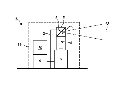
The apparatus depicted in Figs. 1 and 2, designated as a whole with 1,
comprises a fixedly disposed frame 2, in which a laser source 3 is mounted,
with its optical axis 4 directed upwards. Placed above the laser source 3 and
connected with the frame 2 are a pair of bearings 5, in which a shaft 6 is
rotatably bearing-mounted. The shaft 6 is drivable for rotation by an electric
motor 7. Arranged on the shaft is a mirror 8. By drive of the electric motor 7
2
16/03/2015
AMENDED SHEET
CA 02912356 2015-11-12
WO 2014/185780
PCT/NL2014/050306
8
the rotation position of the mirror 8 is adjusted to thereby control the
amount of deflection of the laser beam 4 exiting from the laser source 3 in a
horizontal plane. For the supply of the laser source 3 a supply unit 9 is
present, and for the control of the electric motor 7 and the laser source 3 a
control unit 10 is in place. The whole is accommodated in a housing 11. The
supply unit may be formed by a battery, typically combined with a PV panel,
but may also be formed by a connection to a supply network.
Upon activation of the apparatus, by means of the supply unit 9 and the
control unit 10 the laser source 3 is switched on so that a laser beam 4 exits
from the laser source 3 along the optical axis. This laser beam 4 strikes the
mirror 8, which has an oblique position, so that the laser beam 12 reflected
by the mirror 8 exits in a horizontal direction. With this, the apparatus is
suitable for generating a stationary laser beam, which, as has been
described above, exits in horizontal direction and which is perceived by the
birds, so that the birds are scared away. The laser beam 12, under the
influence of the control unit 10 and the mirror 8, may also exit upwardly
inclined or downwardly inclined. In the latter case the laser beam will then
hit the ground and cause a light spot on the ground which scares away the
birds.
The above concerns a stationary solution; it is also possible, as has already
been explained, to utilize a movable laser beam. To this end, in the above
embodiment, the electric motor 7 is to drive the mirror such that the exiting
laser beam 12 moves in the vertical direction. By the dynamics resulting
from this, the birds are deterred more easily. Such a situation is represented
in Fig. 3. When the mirror is driven with a high speed, the birds perceive
the laser beam as a surface 13. This embodiment requires a fast moving
mirror. While to this end use can be made of a fast rotating electric motor,
CA 02912356 2015-11-12
WO 2014/185780
PCT/NL2014/050306
9
as in the above-described embodiment, it is also possible to utilize for this
purpose an electric driving element having the structure of a galvanometer.
Fig. 4 shows a situation in which two apparatuses la, lb like the one shown
in Fig. 3 are placed on opposite sides of a runway 15. With these, two laser
beams 12 are generated which, as a result of their rapid movement,
apparently form a vertical surface. In the situation shown in Fig. 4, it is
clear how these surfaces keep the runway 15 clear of birds 16 in order to
minimize the danger of an airplane 17 hitting a bird. It is obviously
necessary here that prior to generating the radiation pattern represented in
Fig. 4 the birds 16 be scared off the runway 15, for instance by having either
or both of the laser beams 12 sweep above the runway 15.
Naturally, other configurations are possible; thus, it is possible to dispose
the apparatuses 1 in such a manner that the apparent surfaces 13 extend
transversely to the runway 15. This prevents birds 16 from moving in the
longitudinal direction of the runway to the part where the airplanes 17 land
and take off. It is incidentally noted that it is more attractive when only a
single apparatus 1 according to the invention is present and the laser beam
exiting from the apparatus 1 moves not only in the vertical plane but also in
the horizontal plane. Particularly when the movements in the vertical plane
are fast and the movements in the horizontal plane slower, a surface is
obtained that, to the birds, apparently swerves. This configuration, for that
matter, can also be used in other situations.
Furthermore, the above described apparatuses may be coupled with a
prediction device for predicting the arrival of an airplane, so that the
apparatus is switched on only then. To this end, a link with the installations
of the air traffic control can be made. Also, a link with a presence detector
CA 02912356 2015-11-12
WO 2014/185780
PCT/NL2014/050306
for birds can be made in order to generate a laser beam only when birds are
present.
Finally, Fig. 6 shows a situation in which an apparatus 21 according to the
5 invention is disposed on a helicopter platform 22, for instance on an oil
rig.
On a steel construction 23, which is part of an oil rig not further shown, the
helicopter platform 22 has been placed, as well as an apparatus 21
according to the invention. This apparatus is arranged for generating a laser
beam 25, which is directed towards the helicopter platform 22. The laser
10 beam can then move over the platform 22 in both directions to scare away
birds present on the platform. Furthermore, the apparatus according to the
invention comprises a water cannon 27 placed on the apparatus 21. The
control of the water cannon 27 is then programmed such that the water jet
28 exiting from the water cannon 27 is aimed at the same part of the
platform 22 as the laser beam 25 exiting from the apparatus 21. Upon
simultaneous operation of the laser beam 25 and the water jet 28, the birds
are deterred in two ways at the same time. It is also possible, however, to
use the water jet as an alternative to the laser beam, for instance when due
to glaring sunlight the laser beam is poorly visible to the birds. Also, it is
possible to use the two media alternately.
Also in this embodiment, the laser source or the water cannon may be
arranged to be activated only upon detection of birds or in anticipation of
the arrival or departure of a helicopter. Finally, as in the initially
discussed
embodiment, it is possible to aim the water jet or the laser beam at the place
where birds have been observed.
The embodiment shown in Fig. 7 is suitable for placement on a wind turbine
30. The apparatus 31 according to the invention is placed on a ring 32,
which is arranged rotatably around the tower 33 of the wind turbine 30. The
CA 02912356 2015-11-12
WO 2014/185780
PCT/NL2014/050306
11
apparatus 31 is movable along the ring 32 by drive means not shown. The
apparatus 31 is arranged for radiating a laser beam 34 which extends
obliquely upwards at an angle to the tower 33. The angle is then chosen
such that the laser beam 34 upon rotation of the apparatus along the ring
describes a cone, the cone enveloping the path of the blades 35 of the wind
turbine 30.