Note: Descriptions are shown in the official language in which they were submitted.
81792948
BASE RAIL WITH BUMPER GUARD FOR A TRAILER
[0001] This application claims priority to U.S. Patent Application Ser.
No. 62/096,081 filed December 23, 2014 entitled BASE RAIL OF A TRAILER HAVING
A BUMPER GUARD.
Field Of The Invention:
[0002] The present invention relates generally to semi-trailers, such as
van-type
trailers, for example, In particular, the present invention relates to a
bumper rail for a
semi-trailer.
BACKGROUND OF THE INVENTION
[0003] A typical base rail includes an upper portion that is coupled to
an inner
surface of the sidewalls of the trailer and extends substantially along a
length of the
trailer. During normal use of the trailer, during loading and unloading of
cargo, for
example, the base rail may become damaged due to normal wear and tear. For
example, the wheels of lift trucks that are driven into the storage container
portion of a
trailer may damage the base rail of the trailer due to abrasion of the wheels
against the
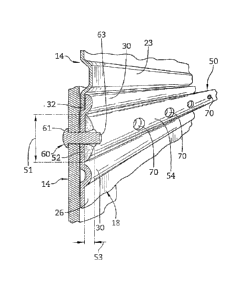
base rail. The lift truck wheels typically include a hard, steel portion that
may impact
and abrade the base rail which is typically extruded from a softer metal such
as
aluminum. The base rail provides structural support to the trailer and
continued
damage to the base rail may result in failure of base rail and possibly to the
accompanying sidewall of the trailer.
[0004] Steel bumper rail covers have been provided in an attempt to cover
and
protect the upper portion of the base rail from the aforementioned damage.
Such
bumper rail covers are fabricated to cover the entire height of the upper
portion of the
base rail such that no portion of the base rail above the floor assembly is
exposed.
While such covers may operate to protect the base rail from damage, such
bumper rail
covers can be costly and heavy and may not be desirable for these reasons.
Date Recue/Date Received 2020-11-19
CA 02912490 2015-11-19
WNC-2014-02
2
SUMMARY
[0005] The present invention may comprise one or more of the features
recited in
the attached claims, and/or one or more of the following features and
combinations
thereof.
[0006] According to one aspect of the present disclosure, a base rail
configured
to be coupled to a sidewall and floor assembly of the trailer includes an
upper portion
configured to be coupled to the inner surface of a sidewall of a trailer. The
upper
portion includes a plurality of spaced-apart ridges configured to extend
inwardly away
from an inner surface of the upper portion and into a storage area of the
trailer. The
base rail further includes a lower portion configured to be coupled to the
floor assembly
of the trailer, a bumper guard coupled to the inner surface of the upper
portion and
positioned between spaced-apart ridges, and a plurality of rivets coupling the
bumper
guard to the base rail. A head of each rivet is configured to be positioned
adjacent an
outside surface of the sidewall of the trailer and an end of each rivet is
substantially
flush With an inner surface of the bumper guard. The bumper guard extends
further
inwardly into the storage area of the trailer than the spaced-apart ridges,
and the
bumper guard is made from a material that is harder than the upper portion of
the base
rail.
[0007] In one illustrative embodiment, the bumper guard may be
approximately 1
inch tall and 5/16 inch wide.
[0008] In another illustrative embodiment, the bumper guard may be made of
steel and the upper portion of the base rail may be made of aluminum.
[0009] In still another illustrative embodiment, the bumper guard may be
generally half-oval in cross-sectional shape such that bumper guard may
include a
planar, outer surface adjacent the inner surface of the upper portion. The
inner surface
of the bumper guard may be curved and configured to extend inwardly into an
interior of
the storage area of the trailer.
[0010] In yet another illustrative embodiment, the bumper guard may include
a
plurality of apertures formed therethrough. Illustratively, each aperture may
be tapered
from an inner surface of the bumper guard to an outer surface of the bumper
guard.
81792948
3
[0011] In still another illustrative embodiment, the bumper guard may be
positioned between the two upper-most raised ridges of the upper portion.
Illustratively, a planar surface of the upper portion between the two upper-
most raised
ridges may define approximately the same height as the bumper guard. Further
illustratively, the bumper guard may be positioned between the two upper-most
rivets
of the plurality of rivets.
[0012] In yet another illustrative embodiment, the bumper guard may be
spaced-apart from the floor assembly and is positioned within an upper half of
the
upper portion.
[0013] According to another aspect of the present disclosure, there is
provided
a base rail configured to be coupled to a sidewall and floor assembly of a
trailer,
comprising: an upper portion configured to be coupled to the inner surface of
a
sidewall of a trailer, wherein the upper portion includes a plurality of
spaced-apart
ridges configured to extend inwardly away from an inner surface of the upper
portion
and into a storage area of the trailer; a lower portion configured to be
coupled to the
floor assembly of the trailer; and a bumper guard coupled to the inner surface
of the
upper portion and positioned between spaced-apart ridges, wherein the bumper
guard includes a plurality of pre-punched apertures formed therethrough, and
wherein each pre-punched aperture is tapered from an inner surface of the
bumper
guard to an outer surface of the bumper guard.
[0014] In one illustrative embodiment, a width of the bumper guard may be
greater than a width of the raised ridges.
[0015] In another illustrative embodiment, the bumper guard may be made
of a
different material than the upper portion of the base rail.
[0016] In yet another illustrative embodiment, the bumper guard may be
made
of a harder material than the upper portion of the base rail.
[0017] In still another illustrative embodiment, the bumper guard may
include a
plurality of apertures formed therethrough. Illustratively, each aperture may
be
tapered from an inner surface of the bumper guard to an outer surface of the
bumper
guard. Further illustratively, the base rail may also include a plurality of
rivets coupling
Date Recue/Date Received 2020-11-19
81792948
3a
the bumper guard to the upper portion of the base rail. Each of the plurality
of rivets
may include a head configured to be positioned adjacent an outside surface of
the
sidewall of the trailer, and an end adjacent and flush with the inner surface
of the
bumper guard.
Date Recue/Date Received 2020-11-19
CA 02912490 2015-11-19
WNC-2014-02
4
[0018] According to yet another aspect of the present disclosure, a
method of
coupling a base rail to a trailer includes coupling an upper portion of the
base rail to an
=
inner surface of the sidewall and placing a bumper guard adjacent an inner
surface of
the upper portion between two raised ridges of the upper portion of the base
rail.
Illustratively, the bumper guard includes pre-punched apertures. The method
further
includes drilling holes through the upper portion of the base rail and the
sidewall using
the pre-punched apertures of the bumper guard as a guide, and inserting rivets
through
the drilled holes and pre-punched apertures from outside the sidewall to
position the
head of the rivet adjacent an outside surface of the sidewall.
[0019] In one illustrative embodiment, inserting rivets may include
bucking an end
of the rivet to create a smooth, inner surface of the base rail.
[0020] In another illustrative embodiment, coupling an upper
portion of the base
rail may include inserting rivets through the base rail and the sidewall in
order to
position the head of the rivets adjacent an inside surface of the upper
portion of the
=. . base rail.
[0021] In still another illustrative embodiment, the method also
includes removing
the bumper guard from the upper portion of the base rail, and coupling a
second
bumper guard to the upper portion of the base rail.
BRIEF DESCRIPTION OF THE DRAWINGS
[0022] FIG. 1 is a sectional view of a portion of a storage
container of a trailer
showing a sidewall of the trailer, a floor assembly of the trailer, and a base
rail coupled
to the floor assembly and the sidewall of the trailer, and further showing a
bumper guard
of the present disclosure to be coupled to an upper portion of the base rail.
[0023] FIG. 2 is a sectional view similar to FIG. 1 further showing
the bumper
guard of the present disclosure coupled to the upper portion of the base rail
in order to
prevent damage to the upper portion of the base rail from the wheel of a lift
truck (not
shown), for example.
[0024] FIG. 3 is a perspective view of a portion of the sidewall
and the base rail of
FIG. 2.
CA 02912490 2015-11-19
WNC-2014-02
[0025] FIG. 4 is a perspective view similar to FIG. 3 showing a rivet
inserted from
the outside of the trailer through the sidewall, the upper portion of the base
rail, and the
bumper guard to provide a smooth outer surface of the bumper guard.
[0026] FIG. 5 is a sectional view of a portion of an alternative storage
container of
a trailer showing a sidewall of the trailer, a floor assembly of the trailer,
an alternative
base rail coupled to the floor assembly and the sidewall and including the
bumper guard
coupled to the upper portion of the alternative base rail.
DETAILED DESCRIPTION OF THE PREFERRED EMBODIMENT
[0027] For the purposes of promoting an understanding. of the principles of
the
invention, reference will now be made to illustrative embodiments shown in the
attached
drawings and specific language will be used to describe the same. While the
concepts
of this disclosure are described in relation to a truck trailer, it will be
understood that
they are equally applicable to other vehicles or storage containers generally,
and more
specifically to conventional box or van type trailers, examples of which
include, but
should not be limited to, straight truck bodies, small personal and/or
commercial trailers
and the like. Accordingly, those skilled in the art will appreciate that the
present
invention may be implemented in a number of different applications and
embodiments
and is not specifically limited in its application to the particular
embodiments depicted
herein.
[0028] A trailer of the present disclosure includes a storage container
having
spaced-apart sidewalls 14 (only a portion of one of which is shown in FIG. 1)
and a floor
assembly 16 coupled to and extending between the sidewalls 14. The storage
container of the trailer further includes a rear end wall assembly (not shown)
and a front
end wall assembly (not shown) each coupled to both the sidewalls 14 and the
floor
assembly 16, as well as a roof assembly (not shown) coupled to the sidewalls
16 and
the rear end wall assembly. A base rail 13 of the storage container is coupled
to each
sidewall 14 and to the floor assembly 16 to run along the length of the
storage
container, as shown in FIG. 1.
CA 02912490 2015-11-19
WNC-2014-02
6
[0029] Illustratively, the base rail 18 includes an upper portion 20
positioned
generally above the floor assembly 16 and a lower portion 22 coupled to and
positioned
generally below the upper portion 20. As shown in FIGS. 1 and 2, the upper
portion 20
is coupled to an inner surface 23 of the sidewall 14 typically using the three
illustrative
rivets 24 shown in FIG. 1 (the upper-most rivet 24 is shown in phantom). As
shown in
FIG. 1, the rivets 24 are inserted from the inside surface 26 of the upper
portion 20 of
the base rail 18 through the sidewall 14 such that the rivet heads 28 are
positioned
adjacent the inside surface 26 of the upper portion 20 and the rivet ends 29
are
positioned adjacent an outside surface 62 of the sidewall 14 of the trailer.
While
illustrative rivets 24 are shown, it is within the scope of this disclosure
for the upper
portion 20 of the base rail 18 to be coupled to the sidewall 14 using any
suitable
fastener and/or adhesive.
[0030] The illustrative upper portion 20 of the base rail 18 includes
raised ridges
30 which, extend horizontally along a length of the base rail 18. Four
illustrative raised
ridges N are provided, though, it is within the scope of this disclosure for
the base rail
18 to include any number of raised ridges 30. The illustrative raised ridges
30 protrude
inwardly toward the interior of the storage container and are vertically
spaced-apart from
each other to define three generally flat, or planar areas 32 therebeween. The
rivets 24
are located within the flat areas 32 so that the heads 28 of the rivets 24 do
not generally
protrude inwardly toward the interior of the storage container beyond the
raised ridges
30.
[0031] The lower portion 22 of the base rail 18 is generally planar and is
coupled
to the floor assembly 16, as shown in FIGS. 1 and 2. The lower portion 22 of
the base
rail 18 is specifically coupled to an outer end of the cross-members 40 of the
floor
assembly 16 using the illustrative nut and bolt fasteners 42 shown. It should
be
understood that any suitable fastener may be used as well. The lower portion
22 of the
base rail 18 is positioned generally directly below the sidewall 14. The base
rail 18
further includes a ledge 44 coupled to and positioned between the upper and
lower
portions 20, 22 of the base rail 18. The ledge 44 extends outwardly away from
an outer
surface of each of the upper and lower portion portions 20, 22 to define an
upper
= = =
=
CA 02912490 2015-11-19
WNC-2014-02
7
surface 46 upon which the lower end of the sidewall 14 rests. The base rail 18
is
typically made of aluminum, though any suitable material may be used.
[0032] In use, the raised ridges 30 of the upper portion 20 of the base
rail 18 are
provided in an effort to protect the rivet heads 28 from general wear and tear
of the
base rail 18 during loading and unloading of cargo to and from the interior of
the storage
container, for example. However, the steel rim of lift truck wheels (not
shown)
oftentimes operates to significantly wear down the raised ridges 30 of the
aluminum
upper portion 20 of the base rail 18. In this event, the steel rim of the lift
truck wheels
may also snag a rivet head 28 and tear the rivet head 28 off. In particular,
the two
upper-most raised ridges 30 typically see the most abrasion by the steel rim
of the lift
= truck wheels such that the rivet head 28 of the uppermost rivets 24 of
the base rail 18
is able to be snagged and torn off the base rail 18. Such damage to the upper
portion
20 of the base rail 18 may lead to structural damage of the base rail 18 and
even failure
of the base rail 18.
[0033] In order to prevent damage to the aluminum base rail .18 due to
abrasion
from the steel rim of the lift truck wheels, .the base rail 18 of the present
disclosure =
includes a bumper guard 50 coupled to the upper portion 20 of the base rail
18. The
illustrative bumper guard 50, shown in FIGS. 1-4 is made of steel, rather than
aluminum, and is therefore much more durable when abraded or impacted by an
object,
such as the steel wheels of the lift truck, for example. Illustratively, while
the bumper
guard 50 is made from steel, it should be understood that the bumper guard 50
may be
made from any suitable material that is harder than the upper portion 20 of
the base rail
20. In particular, the bumper guard 50 may be made from any one or more
plastic(s),
composite(s), metal(s), or metal alloy(s), for example. The illustrative
bumper guard 50
generally forms a semi-oval in cross-section, as shown in FIG. 2, to define a
planar,
outer surface 52 and a curved, inner surface 54. However, the bumper guard 50
may
define any suitable cross-sectional shape such as, for example, rectangular,
square,
triangular, etc. The planar surface 52 of the bumper guard 50 is coupled to
and
engaged with a planar portion 32 of the inner surface 26 of the upper portion
20 of the
base rail 18. In particular, the planar surface 54 of the bumper. guard 50 is
coupled to
. .
. = = = = = = = =
CA 02912490 2015-11-19
WNC-2014-02
8
the upper-most planar surface 32 of the base rail 18 and is, therefore,
positioned
between the two upper-most raised ridges 30 of the base rail 18, as shown in
FIGS. 2-4.
It should be understood, however, that the bumper guard 50 may be coupled to
any of
the planar surfaces 32 of the upper portion 20 of the base rail 18.
[0034] The illustrative bumper guard 50 defines a height 51 of
approximately 1
inch and a width 53 of approximately 5/16 inch. However, the bumper guard 50
may
define any suitable height and width. The width of the bumper guard 50 is
greater than
a width of the raised ridges 30 such that an inward-most portion of the curved
surface
54 of the bumper guard 50 protrudes inwardly into the interior of the storage
container
beyond an inward-most portion of the raised ridges 30 of the upper portion 20
of the
= base rail 18. As such, an object within the interior of the storage
container may impact
the bumper guard 50 instead of the raised ridges 30 of the upper portion 20 of
the base
rail 18. Because the bumper guard 50 is made from a harder material than the
upper
portion 20 of the base rail 18, the bumper guard 50 is better able to resist
damage from
being impacted and abraded by objects within the.storage container.
Accordingly, the
bumper guard 50 operates to protect .the upper portion 20 of the base rail 18
from
damage due to impact and/or abrasion of objects such as, for example, the
steel wheels
of a lift truck.
[0035] Illustratively, the bumper guard 50 is coupled to the upper
portion 20 of the
base rail 18 by rivets 60 inserted from the outside surface 62 of the sidewall
14, through
the sidewall 14, through the upper portion 20 of the base rail 18, and through
the
bumper guard 50, as shown in FIG. 2. As such, the rivet head 61 is located
adjacent
the outer surface 62 of the sidewall 14 while the rivet end 63 is located
adjacent the
curved inner surface 54 of the bumper guard 50. Positioning the rivet head 61
outside
the trailer may operate to resist separation of the bumper guard 50 and upper
portion 20
of the base rail 18 from the sidewall 14 in the event that the trailer
sidewalls 14 are
urged to bow outwardly due to typical stresses seen during normal activity and
use of
the trailer. Illustratively, the bumper guard 50 is pre-punched to form
apertures 70, as
shown in FIGS. 3 and 4. The apertures 70 are pre-punched from the curved
surface 54
through the bumper guard 50 to the planar surface 52 of the bumper guard 50
using a
=
=
=
. .
CA 02912490 2015-11-19
VVNC-2014-02
9
die to create a naturally-tapered through hole. As such, the apertures 70 are
slightly
tapered from the curved surface 54 of the bumper guard 50 to the planar
surface 52 of
the bumper guard 50. The rivet 60 is installed from outside the trailer and is
bucked to
fill the punched and tapered aperture 70 of the bumper guard 50. As such, the
end 63
of the rivet 60 is bucked such that it sits generally flush with the curved
surface 54 in
order to provide a generally snag-free curved surface 54 of the bumper guard
50.
Illustratively, a distance between the centers of adjacent apertures 70 is
approximately
4 inches; however, it should be understood that the apertures 70 may be spaced
any
suitable distance apart from each other.
[0036] In the original manufacture of a trailer, the upper portion 20
of the base rail
18 is coupled to the sidewall 14 of the trailer using the rivets 24 while
leaving off the top- =
most row of the rivets 24 (shown in phantom in FIG. 1) that are typically used
when a
base rail without a bumper guard, such as the bumper guard 50, is provided.
The
bumper guard 50 is then placed between the two top-most raised ridges 30 and
holes
are drilled through the upper portion 20 of the base rail 18 and the sidewall
14 to align
=
with the pre-punched apertures 70. of the bumper guard 50. The apertures 70 of
the =
bumper guard 50 are used as a guide when drilling the holes through the
sidewall and
upper portion 20 of the base rail 18. Once the holes are drilled, rivets 60
are inserted
from the outside of the trailer through the holes in the sidewall 14 and the
upper portion
20 of the base rail 18 as well as through the apertures 70 of the bumper guard
50. As
noted above, the ends 63 of the rivets 60 are bucked to fill the naturally
tapered holes
70 and to create a generally smooth, snag-free outer surface 54 of the bumper
guard
50.
[0037] The bumper guard 50 may also be retrofit onto existing
trailers that
already include a base rail without a bumper guard. To retrofit the bumper
guard 50
onto an existing trailer, any of the remaining top-most rivets 24 (shown in
phantom in
FIG. 1) coupling the upper portion 20 of the base rail to the sidewall 14 of
the trailer are
removed. The bumper guard 50 (including the pre-punched apertures 70) is then
placed onto the upper-most planar surface 32 of the upper portion 20 between
the two
upper-most raised ridges 30. Holes are then back-drilled through the sidewall
14 and
. .
= = = = . .
CA 02912490 2015-11-19
\NNC-2014-02
the upper portion 20 of the base rail using the existing apertures 70 of the
bumper guard
50 as a guide. New rivets 60 are then inserted from the outside surface 62 of
the
sidewall 14 of the trailer, through the new apertures of the sidewall 14 and
the upper
portion of the base rail, as well as through the pre-punched apertures 70 of
the bumper
guard 50, in order to couple the bumper guard 50 to the base rail 18. As noted
above,
the rivets 60 are bucked to fill the naturally tapered holes 70 of the bumper
guard 50
and to create a generally smooth, snag-free outer surface 54 of the bumper
guard 50.
As an alternative to drilling new holes through the sidewall 14 and upper
portion of the
base rail 18, the pre-punched apertures 70 of the bumper guard 50 may be
aligned with
the pre-existing apertures of the sidewall 14 and upper portion of the base
rail through
which the now-removed rivets 24 were located. New rivets may 60 then be
installed
from outside the trailer.
[0038] The bumper guard 50 generally extends the length of the
trailer and may
include any number of base rail sections having any suitable length.
Illustratively, the
= bumper guard 50 operates to .resist the damage from the steel wheel of a
truck lift, or
other cargo or equipment within the storage container. Further, any section of
the
bumper guard 50 is able to be replaced after any amount of wear and tear to
that
= section of the bumper guard 50 occurs. Thus, damage to the upper portion
20 of the
base rail 18, which provides structural support to the trailer, is minimized
if not
prevented, and removal or replacement of the entire base rail 18 due to wear
is
generally eliminated. Further, the bumper guard 50 is a much less-costly and
lighter
option than base rail covers which function to cover the entire upper portion
20 of the
base rail 18 while also effectively and efficiently operating the protect the
most damage-
prone portion of the base rail 18.
[0039] Looking now to FIG. 5, an alternative base rail 118 is
provided. The
alternative base rail 118 is similar to the base rail 18. Thus, like reference
numerals are
used to denote the same or similar components. For example, the alternative
base rail
118 includes an alternative upper portion 120, the ledge 44, and the lower
portion 22.
The alternative upper portion 120 is coupled to the inner surface 23 of the
sidewall 14
=
and the lower portion 22 is coupled to the end of the cross-members 40 of the
floor.
= = = . .
CA 02912490 2015-11-19
VVNC-2014-02
11
assembly 16. The sidewall 14 rests upon the upper surface 46 of the ledge 44
of the
alternative base rail 118. As with the base rail 18, the alternative base rail
118 provides
structural support for the attachment of the sidewall 14 to the floor assembly
26 of the
trailer.
[0040] The alternative base rail 118 includes three rivets 24
coupling the upper
portion 120 of the base rail 118 to the inner surface 23 of the sidewall 14,
As With the
base rail 18, the rivets 24 are positioned so that the rivet heads 28 protrude
inwardly
from the inner surface 26 of the upper portion 120 of the base rail 118 into
the interior of
the storage container. The alternative base rail 118 also includes a plurality
of raised
ridges 30 extending along a length of the base rail 118 and protruding
inwardly into the
interior of the storage container. The alternative base rail 118, however,
only includes
three raised ridges 30, as shown in FIG. 5. Specifically, the base rail 118 is
lacking the
second-highest raised ridge 30 of the base rail 18. In other words, the base
rail 118
extrusion has eliminated the second-highest raised ridge 30 provided on the
base rail
. . 18. The base rail 118 includes the lower-most planar surface 32 of
the inner surface of
= . = the base rail 118 between the two lower-most raised ridges 30 and a
larger planar
surface 132 between the upper-most raised ridge 30 and the middle raised ridge
30.
[0041] The alternative base rail 118 also includes the bumper
guard 50 of the
present disclosure. The bumper guard 50 is positioned between the two top
rivets 24
(i.e., between the upper-most rivet 24 and the middle rivet 24) such that the
planar
surface 52 of the bumper guard 50 is adjacent to and engaged with the large
planar
surface 132 of the base rail 118, and the curved inner surface 54 of the
bumper guard
50 is curved inwardly to extend away from the inner surface 23 of the base
rail 118 into
the interior of the storage container. As with the base rail 18, the bumper
guard 50 of
the base rail 118 is configured to extend further inwardly into the interior
of the storage
container than the rivet heads 28 coupling the upper portion 120 of the base
rail 118 to
the sidewall 14.
[0042] While the invention has been illustrated and described in
detail in the
foregoing drawings and description, the same is to be considered as
illustrative and not
restrictive in character, it being understood that only illustrative
embodiments thereof
= -=
CA 02912490 2015-11-19
VVNC-2014-02
12
have been shown and described and that all changes and modifications that come
within the spirit of the invention are desired to be protected.' =
=
=
=
=
= .