Note: Descriptions are shown in the official language in which they were submitted.
CA 02912704 2015-11-16
WO 2014/186518 PCT/US2014/038093
METHOD AND DEVICE FOR MONITORING OPHTHALMIC LENS
MANUFACTURING CONDITIONS
TECHNICAL FIELD
[0001] The disclosure generally relates to a method and a communication system
device used to monitor manufacturing conditions. More particularly, it relates
to the
method of monitoring controlled manufacturing conditions of an ophthalmic lens
and
generating an unique identifier.
BACKGROUND
[0002] Traditionally, ophthalmic devices, such as a hydrogel lens, an
intraocular
lens or a punctal plug, include corrective, cosmetic or therapeutic qualities.
A contact
lens, for example, may provide vision correcting functionality, cosmetic
enhancement,
and/or therapeutic effects. Each function is provided by a physical
characteristic of the
contact lens. For example, a refractive quality may provide a vision
corrective function,
a pigment may provide a cosmetic enhancement, and an active agent may provide
a
therapeutic functionality.
[0003] Ophthalmic lens manufacturing processes include, for example,
sandwiching a monomer between back curve (upper) and front curve (lower) mold
sections carried in a mold array. The monomer is polymerized, thus forming a
lens,
which is then removed from the mold sections and further treated in a
hydration bath and
packaged for consumer use. A more recently developed manufacturing process for
manufacturing high quality customized ophthalmic lenses is disclosed in U.S.
Patent No.
7,905,594 to Widman, et al. which is assigned to the assignee of the present
disclosure.
[0004] In order to reach greater design ranges and higher optical quality,
currently, these and other manufacturing techniques are carried out by
partially
automated and semi-automated apparatus and processes with strict process
controls and
tight tolerances necessary for the production of high quality ophthalmic
lenses. Evolving
1
CA 02912704 2015-11-16
WO 2014/186518 PCT/US2014/038093
techniques employ different process controls seeking to improve or add a
particular
manufacturing step. Examples of newly developed methodologies include new ways
of
demolding the lens from the mold part, the application of binder layers to the
mold parts,
polymerization techniques, lens hydration techniques, metrology techniques,
lens
material development, and the such.
[0005] With new methods and lens components being developed, the complexity
of troubleshooting the desired automated process controls is sometimes
greater. In
addition, because some faults may not be detected prior to the detection of a
defective
ophthalmic lens during quality control, fault identification and correction
can often be
subject to a time delay wasting production time and materials. As a result,
while the
aforementioned production processes have some efficacy in the production of
soft contact
lenses, they suffer a number of disadvantages which can hinder the development
of a
high speed automated production line capable of producing high quality
ophthalmic
lenses. Furthermore, with the increasing risk of these high quality ophthalmic
lenses
being counterfeited, it is desirous for the ophthalmic lens to include a
communication
system useful to provide information about the ophthalmic lens' production.
[0006] Therefore, there is a need for a communication system that can be
incorporated in an ophthalmic lens and/or mold part during early stages of
manufacturing
and which can be useful to generate a unique identifier with correlated
production
information.
SUMMARY
[0007] Accordingly, the foregoing needs are met, to a great extent, by one or
more embodiments of the communication system. In accordance with some
embodiments, the communication system includes a nano-antenna incorporated
into or
onto an ophthalmic device during manufacturing and is coded with an unique
identifier.
2
CA 02912704 2015-11-16
WO 2014/186518 PCT/US2014/038093
[0008] According to aspects of the disclosure, a method of monitoring
ophthalmic lens manufacturing controlled conditions is disclosed. The method
can
comprise: placing a communication system on a lens forming surface of a mold;
energizing a communication system; storing a unique identifier in the
communication
system; measuring a controlled condition during manufacturing of the
ophthalmic lens
using at least one or more sensor(s) in the communication system; transmitting
sensor
data relating to the measured condition to a processor; and identifying a
deficiency in the
controlled condition using the sensor data and the unique identifier.
[0009] In some embodiments of the disclosure, an ophthalmic lens can include:
a
hydrogel portion supporting a communication system; the communication system
comprising: a processor in logical communication with one or more sensor(s)
configured
to measuring a controlled condition during manufacturing of the ophthalmic
lens; a
nano-antenna capable of receiving energy to energize the processor and the one
or more
sensor(s) and transmit sensor data relating to the measured controlled
condition; and
wherein the processor is capable of storing a unique identifier.
[0010] Certain implementations of the ophthalmic device and communication
system including the antenna configuration have been outlined so that the
detailed
description below may be better understood.
There are, of course, additional
implementations that will be described below and which will form the subject
matter of
the claims.
[0011] In this respect, before explaining at least one implementation in
detail, it is
to be understood that the hydrogel lens including the communication system is
not
limited in its application to the details of construction and to the
arrangements of the
components set forth in the following description or illustrated in the
drawings. Also, it
is to be understood that the phraseology and terminology employed herein, as
well as in
the Abstract, are for the purpose of description and should not be regarded as
limiting.
3
CA 02912704 2015-11-16
WO 2014/186518 PCT/US2014/038093
[0012] As such, those skilled in the art will appreciate that the conception
upon
which this disclosure is based may readily be utilized as a basis for the
designing of other
structures, methods, and systems for carrying out the several purposes of the
ophthalmic
lens including the control, subsequent to the manufacturing of the ophthalmic
lens, of
dynamic components that may be included in some embodiments. It is understood,
therefore, that the claims include such equivalent constructions insofar as
they do not
depart from the spirit and scope of the present application.
BRIEF DESCRIPTION OF THE DRAWINGS
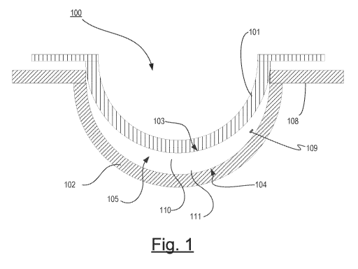
[0013] FIG. 1 illustrates a cross section of a mold assembly apparatus
according
to some embodiments of the disclosure.
[0014] FIG. 2 illustrates an ophthalmic lens with a communication system
including an energy receptor according to some embodiments of the disclosure.
[0015] FIG. 3 illustrates another ophthalmic lens with a media insert
comprising a
communication system according to some embodiments of the disclosure.
[0016] FIG. 4 illustrates a schematic design of a communication system
comprising an exemplary nano-antenna according to some aspects of the
disclosure.
[0017] FIG. 5 illustrates an ophthalmic lens manufacturing apparatus that may
be
used to position a communication system in a mold part for an ophthalmic lens.
[0018] FIG. 6 illustrates a processor that may be used to implement some
embodiments of the disclosure.
[0019] FIG. 7 illustrates method steps that may be used to generate an
ophthalmic
lens pedigree profile during manufacturing.
[0020] FIG. 8 illustrates method steps that may be used to monitor and/or
troubleshoot manufacturing controlled conditions.
4
CA 02912704 2015-11-16
WO 2014/186518 PCT/US2014/038093
DETAILED DESCRIPTION
[0021] A communication system for an ophthalmic lens is disclosed. The
communication system may be used to monitor manufacturing controlled
conditions and
identify deficiencies in the system in a sensible manner. In some embodiments,
the
communication system can also be used to generate a Lens Pedigree Profile that
can be
useful to ensure the correct ophthalmic lens reaches the consumer. For
example, the Lens
Pedigree Profile can include lens design information useful to verify the
authenticity of
the ophthalmic lens.
GLOSSARY
[0022] In the description and the claims, various terms may be used for which
the
following definitions will apply:
[0023] Active Lens Insert: as used herein, may refer to an electronic or
electromechanical insert device with controls based upon logic circuits.
[0024] Communication System: as used herein, may refer to a wireless
communication device that can be configured to transmit and receive
electromagnetic
radiation from its components. In some embodiments, the communication system
can
include a nano-antenna, such as a nano-fractal antenna or a nano-yagi-uda type
of
antenna architecture, and a nano-scale sensor, processor and nano-transceiver.
In some
preferred embodiments, the communication system can be of negligible size and
be
without consequence in most optical plastic polymer or resin applications. In
alternative
embodiments, significantly opaque components of larger communication systems
that
would impede vision may be positioned outside of the optical zone, for
example, forming
part of a Media Insert.
[0025] Energized: as used herein, may refer to the state of being able to
supply
electrical current to or to have electrical energy stored within.
CA 02912704 2015-11-16
WO 2014/186518 PCT/US2014/038093
[0026] Energy: as used herein, may refer to the capacity of a physical system
to
do work. Many uses within this disclosure may relate to the said capacity
being able to
perform electrical actions in doing work.
[0027] Energy Receptor: as used herein, may refer to a medium that can
functions
as an antenna for receiving wireless energy, such as, for example via radio
wave
transmission.
[0028] Energy Source: as used herein, may refer to device or layer which is
capable of supplying Energy or placing a logical or electrical device in an
Energized
state.
[0029] Functionalized Layer Insert: as used herein, may refer to an insert for
an
ophthalmic device formed from multiple functional layers from which at least a
portion
of the multiple functional layers are stacked. The multiple layers may have
unique
functionality for each layer; or alternatively mixed functionality in multiple
layers. In
some embodiments, the layers can be rings.
[0030] Lens Design: as used herein, may refer to form, function and/or
appearance of a desired Lens, which if fabricated, may provide functional
characteristics
comprising but not limited to optical power correction, color appearance,
therapeutic
functionality, wearability, acceptable permeability, shape, composition,
conformability,
acceptable lens fit (e.g., corneal coverage and movement), and acceptable lens
rotation
stability.
[0031] Lens Forming Mixture: as used herein, the term "lens forming mixture"
or
"Reactive Mixture" or "RMM"(reactive monomer mixture) refers to a monomer or
prepolymer material which can be cured and crosslinked or crosslinked to form
an
Ophthalmic Lens. Various embodiments can include lens forming mixtures with
one or
more additives such as: UV blockers, tints, photoinitiators or catalysts, and
other
additives one might desire in an ophthalmic lenses such as, contact or
intraocular lenses.
6
CA 02912704 2015-11-16
WO 2014/186518 PCT/US2014/038093
[0032] Lens Forming Surface: as used herein, may refer to a surface that is
used
to mold at least a portion of a lens. In some embodiments, any such surface,
for example
103-104, can have an optical quality surface finish, which indicates that it
is sufficiently
smooth and formed so that a lens surface fashioned by the polymerization of a
lens
forming material in contact with the molding surface is optically acceptable.
Further, in
some embodiments, the lens forming surface can have a geometry that is
necessary to
impart to the lens surface the desired optical characteristics, including
without limitation,
spherical, aspherical and cylinder power, wave front aberration correction,
corneal
topography correction and the like as well as any combinations thereof
[0033] Media Insert: as used herein, may refer to a formable or rigid
substrate
capable of supporting an energization element, such as a battery, within an
ophthalmic
lens. In some embodiments, the media insert also includes one or more variable
optic
lenses and communication systems.
[0034] Mold: as used herein, may refer to a rigid or semi-rigid object that
may be
used to form lenses from uncured formulations. Some molds can include one or
more
mold parts used to form a hydrogel lens comprising raised portions.
[0035] Ocular Surface: as used herein, may refer to the anterior surface area
of
the eye.
[0036] Ophthalmic Lens: as used herein, may refer to any ophthalmic device
that
resides in or on the eye. These devices can provide optical correction or may
be
cosmetic. For example, the term lens can refer to a contact lens, intraocular
lens, overlay
lens, ocular insert, optical insert or other similar device through which
vision is corrected
or modified, or through which eye physiology is cosmetically enhanced (e.g.
iris color)
without impeding vision. In some embodiments, the preferred lenses of the
disclosure
are soft contact lenses are made from silicone elastomers or hydrogels, which
include but
are not limited to silicone hydrogels, and fluorohydrogels.
7
CA 02912704 2015-11-16
WO 2014/186518 PCT/US2014/038093
[0037] Optical Zone: as used herein, may refer to an area of an ophthalmic
device
or lens through which a wearer of the ophthalmic lens sees after the lens is
formed.
[0038] Peripheral Zone: as used herein, the term "peripheral zone" or "non-
optic
zone" may refer to an area of an ophthalmic lens outside of the optic zone of
the
ophthalmic lens, and therefore outside of a portion of the ophthalmic lens
through which
a lens wearer sees while wearing the ophthalmic lens on, near or in the eye in
a normally
prescribed fashion.
[0039] Pedigree Profile: as used herein, may refer to the background and/or
manufacturing history of an ophthalmic lens. In some preferred embodiments,
the
pedigree profile can include, for example, one or more of: lens corrective
specifications,
base curve, material(s), encrypted digital identification data, manufacturing
facility
information, and authentication data.
[0040] Released from a Mold: as used herein, may refer to a lens that is
either
completely separated from the mold, or is only loosely attached so that it can
be removed
with mild agitation or pushed off with a swab.
[0041] Referring now to Fig. 1, a diagram of an exemplary Mold for an
Ophthalmic Lens with a Communication System 109 is illustrated. As used
herein, the
term Mold can include a mold assembly 100 having a cavity 105 into which a
Lens
forming mixture 110 can be dispensed such that upon reaction or cure of the
Lens
Forming Mixture, an Ophthalmic Lens of a desired shape is produced. In some
embodiments, the Molds and mold assemblies 100 may be made up of more than one
"mold parts" or "mold pieces" 101-102. For example, the mold parts 101-102 can
be
brought together such that a cavity 105 is formed between the mold parts 101-
102 in
which a lens can be formed. This combination of mold parts 101-102 is
preferably
temporary. Upon formation of the Ophthalmic Lens, the mold parts 101-102 can
again
be separated and the Ophthalmic Lens can be Released from a Mold.
8
CA 02912704 2015-11-16
WO 2014/186518 PCT/US2014/038093
[0042] At least one mold part 101-102 has at least a portion of its Lens
Forming
Surface 103-104 in contact with the Lens Forming Mixture such that upon
reaction or
cure of the Lens Forming Mixture 110 that surface 103-104 provides a desired
shape and
form to the portion of the Ophthalmic Lens with which it is in contact. The
same may be
true of at least one other mold part 101-102.
[0043] Thus, for example, in one preferred embodiment a mold assembly 100 can
be formed from two parts 101-102, a female concave piece (front piece) 102 and
a male
convex piece (back piece) 101 with a cavity formed between them. The portion
of the
concave surface 104 which can make contact with Lens Forming Mixture 110 has
the
curvature of the front curve of an Ophthalmic Lens to be produced in the mold
assembly
100 and is sufficiently smooth and formed such that the surface of an
Ophthalmic Lens
formed by polymerization of the Lens Forming Mixture which is in contact with
the
concave surface 104 is optically acceptable.
[0044] In some embodiments, the front mold piece 102 can also have an annular
flange integral with and surrounding circular circumferential edge 108 and
extends from
it in a plane normal to the axis and extending from the flange (not shown).
[0045] A Lens Forming Surface can include a surface 103-104 with an optical
quality surface finish, which indicates that it is sufficiently smooth and
formed so that an
Ophthalmic Lens surface fashioned by the polymerization of a Lens Forming
Mixture in
contact with the molding surface is optically acceptable. Further, in some
embodiments,
the Lens Forming Surface 103-104 can have a geometry that may be necessary to
impart
to the lens surface the desired optical characteristics, including without
limitation,
spherical, aspherical and cylinder power, wave front aberration correction,
corneal
topography correction and the like as well as any combinations thereof
[0046] Mold part 101-102 material can include a polyolefin of one or more of:
polypropylene, polystyrene, polyethylene, polymethyl methacrylate, and
modified
9
CA 02912704 2015-11-16
WO 2014/186518 PCT/US2014/038093
polyolefins. A preferred alicyclic co-polymer contains two different alicyclic
polymers
and is sold by Zeon Chemicals L.P. under the trade name ZEONOR. There are
several
different grades of ZEONOR. Various grades may have glass transition
temperatures
ranging from 105 C to 160 C. A specifically preferred material is ZEONOR
1060R.
Other Mold materials that may be combined with one or more additives to form
an
Ophthalmic Lens Mold include, for example, Zieglar-Natta polypropylene resins
(sometimes referred to as znPP). On exemplary Zieglar-Natta polypropylene
resin is
available under the name PP 9544 MED. PP 9544 MED is a clarified random
copolymer
for clean molding as per FDA regulation 21 CFR (c)3.2 made available by
ExxonMobile
Chemical Company. PP 9544 MED is a random copolymer (znPP) with ethylene group
(hereinafter 9544 MED). Other exemplary Zieglar-Natta polypropylene resins
include:
Atofina Polypropylene 3761 and Atofina Polypropylene 3620WZ. Still further, in
some
embodiments, the Molds of the disclosure may contain polymers such as
polypropylene,
polyethylene, polystyrene, polymethyl methacrylate, modified polyolefins
containing an
alicyclic moiety in the main chain and cyclic polyolefins. This blend can be
used on
either or more Mold parts, for example, where it is preferred that this blend
is used on the
back curve and the front curve consists of the alicyclic co-polymers.
[0047] In some preferred methods of making Molds 100, injection molding can
be utilized according to known techniques, however, embodiments can also
include
Molds fashioned by other techniques including, for example: lathing, diamond
turning, or
laser cutting. Typically, lenses are formed on at least one surface of both
Mold parts 101-
102. However, in some embodiments, one surface of an Ophthalmic Lens may be
formed from a Mold part 101-102 and another surface of a lens can be free-
formed as
described by other methods.
Lenses
CA 02912704 2015-11-16
WO 2014/186518 PCT/US2014/038093
[0048] Referring now to Fig. 2, an exemplary Ophthalmic Lens 201 is
illustrated
with a Communication System 109, including a nano-antenna 401 (shown in Fig.
4) and a
nano-processing device 404 (shown in Fig. 4). As shown in Fig. 4, the nano-
antenna 401
can be an Energy Receptor and may be a fractal nano-antenna of a conductive
material,
such as, a metallic material. Suitable metallic materials can include, for
example, gold,
grapheme, silver and copper. Conductive fibers such as conductive carbon
fibers can
also be suitable.
[0049] The nano-antenna 401 can be in electrical communication with a
processing device 404. The processing device 404 can include any semiconductor
type
chip. In some specific embodiments, the processing device includes one or more
nan-
sensor(s) 406 (shown in Fig. 4). The processing device 404 may also include
multiple
devices or circuitry. In an effort to provide simplicity in this description,
the one or more
devices will generally be referred to in the singular.
[0050] Referring back to Fig. 2, as illustrated, the Communication System 109
can be located outside of an Optical Zone 202, wherein the Optical Zone 202
includes
that portion of the Ophthalmic Lens 201 providing line of sight for a wearer
of the
Ophthalmic Lens 201. In some embodiments, the Communication System 109 may be
small enough to not have a significant optical effect when it is placed in the
Optical Zone
202 and its location may not be constrained to the Peripheral Zone.
[0051] A preferred Ophthalmic Lens type can include a Ophthalmic Lens 201 that
includes a silicone containing component. A "silicone-containing component" is
one that
contains at least one [-Si-0-] unit in a monomer, macromer or prepolymer.
Preferably,
the total Si and attached 0 are present in the silicone-containing component
in an amount
greater than about 20 weight percent, and more preferably greater than 30
weight percent
of the total molecular weight of the silicone-containing component. Useful
silicone-
containing components preferably comprise polymerizable functional groups such
as
11
CA 02912704 2015-11-16
WO 2014/186518 PCT/US2014/038093
acrylate, methacrylate, acrylamide, methacrylamide, vinyl, N-vinyl lactam, N-
vinylamide, and styryl functional groups. Suitable silicone containing
components
include compounds of:
Formula I
R1 R1 R1
I I I
R1¨Si¨O-Si-O-Si-R1
1 1 1
R1- RI_b Fl
where Rl is independently selected from monovalent reactive groups, monovalent
alkyl groups, or monovalent aryl groups, any of the foregoing which may
further
comprise functionality selected from hydroxy, amino, oxa, carboxy, alkyl
carboxy,
alkoxy, amido, carbamate, carbonate, halogen or combinations thereof; and
monovalent
siloxane chains comprising 1-100 Si-0 repeat units which may further comprise
functionality selected from alkyl, hydroxy, amino, oxa, carboxy, alkyl
carboxy, alkoxy,
amido, carbamate, halogen or combinations thereof; where b = 0 to 500, where
it is
understood that when b is other than 0, b is a distribution having a mode
equal to a stated
value; wherein at least one Rl comprises a monovalent reactive group, and in
some
embodiments between one and 3 Rl comprise monovalent reactive groups.
[0052] As used herein "monovalent reactive groups" are groups that can undergo
free radical and/or cationic polymerization. Non-limiting examples of free
radical
reactive groups include (meth)acrylates, styryls, vinyls, vinyl ethers,
Ci_6alkyl(meth)acrylates, (meth)acrylamides,
Ci_6alkyl(meth)acrylamides, N-
vinyllactams, N-vinylamides, C2_12alkenyls, C2_12alkenylphenyls,
C2_12alkenylnaphthyls,
C2_6 alkenylphenyl C1_6 alkyls, 0-vinylcarbamates and 0-vinylcarbonates. Non-
limiting
examples of cationic reactive groups include vinyl ethers or epoxide groups
and mixtures
thereof In one embodiment the free radical reactive groups comprises
(meth)acrylate,
acryloxy, (meth)acrylamide, and mixtures thereof Suitable monovalent alkyl and
aryl
12
CA 02912704 2015-11-16
WO 2014/186518 PCT/US2014/038093
groups include unsubstituted monovalent Ci to C16 alkyl groups, C6-C14 aryl
groups, such
as substituted and unsubstituted methyl, ethyl, propyl, butyl, 2-
hydroxypropyl,
propoxypropyl, polyethyleneoxypropyl, combinations thereof and the like.
[0053] In one embodiment b is zero, one Rl is a monovalent reactive group, and
at least 3 Rl are selected from monovalent alkyl groups having one to 16
carbon atoms,
and in another embodiment from monovalent alkyl groups having one to 6 carbon
atoms.
Non-limiting examples of silicone components of this embodiment include 2-
methyl-,2-
hydroxy-3-[3-[1,3,3,3 -tetramethy1-1-[(trimethylsily1)oxy]
disiloxanyl]propoxy]propyl
ester ("SiGMA"), 2-hydroxy-3-methacryloxypropyloxypropyl-tris
(trimethylsiloxy)
silane, 3-methacryloxypropyltris(trimethylsiloxy)silane ("TRIS"),
3-methacryloxypropylbis(trimethylsiloxy)methylsilane and
3 -methacryloxypropylp entamethyl disiloxane.
[0054] In another embodiment, b is 2 to 20, 3 to 15 or in some embodiments 3
to
10; at least one terminal Rl comprises a monovalent reactive group and the
remaining Rl
are selected from monovalent alkyl groups having 1 to 16 carbon atoms, and in
another
embodiment from monovalent alkyl groups having 1 to 6 carbon atoms. In yet
another
embodiment, b is 3 to 15, one terminal Rl comprises a monovalent reactive
group, the
other terminal Rl comprises a monovalent alkyl group having 1 to 6 carbon
atoms and the
remaining Rl comprise monovalent alkyl group having 1 to 3 carbon atoms. Non-
limiting examples of silicone components of this embodiment include (mono-(2-
hydroxy-
3-methacryloxypropy1)-propyl ether terminated polydimethylsiloxane (400-1000
MW))
("OH-mPDMS"), monomethacryloxypropyl terminated mono-n-butyl terminated
polydimethylsiloxanes (800-1000 MW), ("mPDMS"). In another embodiment b is 5
to
400 or from 10 to 300, both terminal Rl comprise monovalent reactive groups
and the
remaining Rl are independently selected from monovalent alkyl groups having 1
to 18
13
CA 02912704 2015-11-16
WO 2014/186518 PCT/US2014/038093
carbon atoms which may have ether linkages between carbon atoms and may
further
comprise halogen.
[0055] In one embodiment, where a silicone hydrogel lens is desired, the lens
of
the present disclosure will be made from a reactive mixture comprising at
least about 20
and preferably between about 20 and 70% wt silicone containing components
based on
total weight of reactive monomer components from which the polymer is made. In
another embodiment, one to four Rl comprises a vinyl carbonate or carbamate of
the
formula:
Formula II
H2C=6-(CH2)q-0-8-Y
wherein: Y denotes 0-, S- or NH-; R denotes, hydrogen or methyl; d is 1, 2, 3
or
4; and q is 0 or 1.
[0056] The silicone-containing vinyl carbonate or vinyl carbamate monomers
specifically include: 1,3 -bis [4-(vinyloxycarbonyloxy)but-l-yl] tetramethyl-
disiloxane ; 3-
(vinyloxycarbonylthio) propyl-[tris (trimethylsiloxy)silane]; 3-
[tris(trimethylsiloxy)silyl]
propyl allyl carbamate; 3-[tris(trimethylsiloxy)silyl] propyl vinyl carbamate;
trimethylsilylethyl vinyl carbonate; trimethylsilylmethyl vinyl carbonate, and
where biomedical devices with modulus below about 200 are desired, only one Rl
shall
comprise a monovalent reactive group and no more than two of the remaining Rl
groups
will comprise monovalent siloxane groups.
-
o
CH3 CH3 -cH3 o
11 I I I II
H2c=c¨oco(cH3)4 si o ____________ Si ¨O __ si (cH2)4oco-c=c1-12
H
1 1 1 H
CH3 CH3 CH3
- -25
[0057] Another class of silicone-containing components includes polyurethane
macromers of the following formulae:
14
CA 02912704 2015-11-16
WO 2014/186518 PCT/US2014/038093
Formula IV-VI
(*D*A*D*G)a *D*D*El; E(*D*G*D*A)a *D*G*D*E1 or; E(*D*A*D*G)a
*D*A*D*E1
wherein: D denotes an alkyl diradical, an alkyl cycloalkyl diradical, a
cycloalkyl
diradical, an aryl diradical or an alkylaryl diradical having 6 to 30 carbon
atoms, G
denotes an alkyl diradical, a cycloalkyl diradical, an alkyl cycloalkyl
diradical, an aryl
diradical or an alkylaryl diradical having 1 to 40 carbon atoms and which may
contain
ether, thio or amine linkages in the main chain; * denotes a urethane or
ureido linkage; a
is at least 1; A denotes a divalent polymeric radical of formula:
Formula VII
¨R11¨ R11
I I
¨(CH2)y¨SiO¨Si¨(C H2)y¨
RIi i RI1 1
¨ ¨11
R" independently denotes an alkyl or fluoro-substituted alkyl group having 1
to10 carbon atoms which may contain ether linkages between carbon atoms; y is
at least
1; and p provides a moiety weight of 400 to 10,000; each of E and El
independently
denotes a polymerizable unsaturated organic radical represented by formula:
Formula VIII
R12
1
R13CH=C¨(CH2)w¨(X)x¨(Z)z¨(Ar)y¨R14¨
wherein: R12 is hydrogen or methyl; R13 is hydrogen, an alkyl radical having 1
to
6 carbon atoms, or a ¨CO--Y--R'5 radical wherein Y is ¨0¨,Y¨S¨ or ¨NH¨;
R14 is a divalent radical having 1 to 12 carbon atoms; X denotes ¨CO¨ or
¨000¨; Z
denotes ¨0¨ or ¨NH¨; Ar denotes an aromatic radical having 6 to 30 carbon
atoms;
w is 0 to 6; x is 0 or 1; y is 0 or 1; and z is 0 or 1. A preferred silicone-
containing
component is a polyurethane macromer represented by the following formula:
CA 02912704 2015-11-16
WO 2014/186518
PCT/US2014/038093
Formula IX
0
0
9 2 r3 } 4II II II 1H3
C H2= C- COCI-12 - CC N- R16- NOCCH 2CH 2CC H2CH 20CN- R16-NCC(CH2)e0)&¨(CH26
OCN-Ris- NOCCH2CH2OCH CO220022CH2CCN¨ R16¨ O¨CH2CH2COOCH2
H I I I I I
CH3 CH3 H H H H
a
wherein R16 is a diradical of a diisocyanate after removal of the isocyanate
group, such as
the diradical of isophorone diisocyanate. Another suitable silicone containing
macromer
is compound of formula X (in which x + y is a number in the range of 10 to 30)
formed
by the reaction of fluoroether, hydroxy-terminated polydimethylsiloxane,
isophorone
diisocyanate and isocyanatoethylmethacrylate.
Formula X
0 0
)t
NH
0
-,'"11 ."==-/NHK'cr-(S14e20)25SMe20
NH
0
0cH2cF2¨(0cF2)x¨(0cF2cF2)y-0cF2,-,20
-- NH1-0(S14e20)25S14e2 O I\11,_
NH
[0058] Other silicone containing components suitable for use in this
disclosure
include macromers containing polysiloxane, polyalkylene ether, diisocyanate,
polyfluorinated hydrocarbon, polyfluorinated ether and polysaccharide groups;
polysiloxanes with a polar fluorinated graft or side group having a hydrogen
atom
attached to a terminal difluoro-substituted carbon atom; hydrophilic siloxanyl
methacrylates containing ether and siloxanyl linkanges and crosslinkable
monomers
containing polyether and polysiloxanyl groups. Any of the foregoing
polysiloxanes can
also be used as the silicone containing component in this disclosure.
[0059] Referring now to Fig. 3 a three dimensional cross section
representation is
illustrated of an exemplary Ophthalmic Lens 300 including a Functionalized
Layer Media
Insert 320 configured to include Communication System components on one or
more of
its layers 330, 331, 332. In the present exemplary embodiment, the Media
Insert 320
16
CA 02912704 2015-11-16
WO 2014/186518 PCT/US2014/038093
surrounds the entire periphery of the Ophthalmic Lens 300. One skilled in the
art can
understand that the actual Media Insert 320 may comprise a full annular ring
or other
shapes that still may reside inside or on the hydrogel portion of the
Ophthalmic lens 300
and be within the size and geometry constraints presented by the ophthalmic
environment
of the user.
[0060] Layers 330, 331 and 332 are meant to illustrate three of numerous
layers
that may be found in a Media Insert 320 formed as a stack of functional
layers. In some
embodiments, for example, a single layer may include one or more of: active
and passive
components and portions with structural, electrical or physical properties
conducive to a
particular purpose including the Communication System functions described in
the
present disclosure. Furthermore, in some embodiments, a layer 330 may include
an
Energy Source, such as, one or more of: a battery, a capacitor and a receiver
within the
layer 330. Item 331 then, in a non-limiting exemplary sense may comprise
microcircuitry in a layer that detects actuation signals for the Ophthalmic
Lens 300. In
some embodiments, a power regulation layer 332, may be included that is
capable of
receiving power from external sources, charges the battery layer 330 and
controls the use
of battery power from layer 330 when the Ophthalmic Lens 300 is not in a
charging
environment. The power regulation may also control signals to an exemplary
active lens,
demonstrated as item 310 in the center annular cutout of the Media Insert 320.
[0061] An energized lens with an embedded Media Insert 320 may include an
energy source, such as an electrochemical cell or battery as the storage means
for the
energy and in some embodiments, encapsulation, and isolation of the materials
comprising the energy source from an environment into which an Ophthalmic Lens
is
placed. In some embodiments, a Media Insert 320 can also include a pattern of
circuitry,
components, and energy sources. Various embodiments may include the Media
Insert
320 locating the pattern of circuitry, components and Energy Sources around a
periphery
17
CA 02912704 2015-11-16
WO 2014/186518 PCT/US2014/038093
of an Optic Zone through which a wearer of an Ophthalmic Lens would see, while
other
embodiments may include a pattern of circuitry, components and Energy Sources
which
are small enough to not adversely affect the sight of the Ophthalmic Lens
wearer and
therefore the Media Insert 320 may locate them within, or exterior to, an
Optical Zone.
[0062] Referring now to Fig. 4, a schematic design of the exemplary
Communication System 109 of Fig. 1 comprising a nano-antenna 401 according to
some
aspects of the disclosure is illustrated. In some preferred embodiments, the
nano-antenna
401 can be a fractal antenna configured to operate at different frequencies.
The nano-
antenna 401 may be made up of a conductive material, such as, a metallic
material.
Suitable metallic materials can include, for example, gold, grapheme, silver
and copper.
Conductive fibers such as conductive carbon fibers can also be suitable. The
nano-
antenna may function as an energy receptor configured to provide a self-
powered nano-
Communication System 109, for example, when it is exposed to a heavy radial
frequency
field absorbing enough energy to power other electronic components. A fractal
shape
may include a repeating pattern or any other mathematical set that has a
dimension that
usually exceeds its topological dimension. Another type of nano-antenna 401
can include
a nano-optical Yagi-Uda antenna or the such.
[0063] In some embodiments, the nano-antenna 401 can be in communication
nano-transceiver 402 which may be configured to perform functions including
baseband
processing, frequency conversion, filtering and power amplification, of the
received
signals transmitted into and/or out of the nano-antenna 401. A nano-actuator
403 may
also be included in the Communication System 109 to allow one or more nano-
sensor(s)
406 to interact with the surrounding environment. Nano-
sensors can include, for
example, one or more of: physical nano-sensors capable of measuring mass,
pressure,
force, and/or displacement; chemical nano-sensors configured to measure
chemical
compositions and/or concentrations; and, biological nan-sensors configured to
measure
18
CA 02912704 2015-11-16
WO 2014/186518 PCT/US2014/038093
antibody/antigen interaction, DNA interaction, and/or enzymatic interactions.
Nano-
actuator 403 may include one or more of: physical, chemical or biological
actuators. A
nano-processing device 404 comprising nano-memory 405 in communication with
the
sensor 406 can function, for example, to control the recording measured
conditions by the
sensor 406, execute operational sequences, generate and/or transmit data
related to the
Ophthalmic Lens Pedigree Profile.
[0064] In general, according to the embodiments previously described, a Media
Insert 320 and/or self-powered nano-Communication System 109 can be embodied
within or on an ophthalmic lens via automation which can places/deposit the
components
on a desired location relative to a mold part used to fashion the Ophthalmic
Lens.
Apparatus
[0065] Referring now to Fig. 5, automated apparatus 510 is illustrated with
one or
transfer interfaces 511. As illustrated, multiple mold parts can each be
associated with a
mold part receptacle 514 contained within a pallet 513 and presented to the
transfer
interface(s) 511. The transfer interface(s) 511 can place or deposit a
standalone
Communication System (shown in Fig. 4) or a Media Insert (shown in Fig. 3)
containing
the Communication System configured to generate an Ophthalmic Lens Pedigree
Profile.
Embodiments can include, for example, a single interface individually placing
a single
Communication System on a programmed manner onto a mold part receptacle 514,
or
multiple interfaces (not shown) simultaneously placing multiple Communication
Systems
within multiple mold parts, and in some embodiments, within each mold part.
[0066] Another aspect of some embodiments includes apparatus to support the
Communication System while the hydrogel body of the Ophthalmic Lens is molded
around the Communication System. For example, in some embodiments the
communication system may affix to holding points in a Mold (not illustrated).
In some
19
CA 02912704 2015-11-16
WO 2014/186518 PCT/US2014/038093
embodiments, the holding points may preferably be affixed with polymerized
material of
the same type that will be formed into the lens body.
[0067] Referring now to Fig. 6, a schematic diagram of a controller 600 that
may
be used with some embodiments of the present disclosure is illustrated. The
controller
600 includes a processor 610, which may include one or more processor
components
coupled to a communication device 620. In some embodiments, a controller 600
can be
used to transmit energy to the energy source placed in the Ophthalmic Lens.
[0068] The controller 600 can include one or more processors 610, coupled to a
communication device 620 configured to communicate logical signals via a
communication channel. The communication device 620 may be used to
electronically
control one or more of: the placement of a microcontroller and a flexible
media into the
Ophthalmic Lens and the transfer of command to operate a component or the
microcontroller.
[0069] The communication device 620 may also be used to communicate, for
example, with one or more controller apparatus or manufacturing equipment
components.
[0070] The processor 610 is also in communication with a storage device 630.
The storage device 630 may comprise any appropriate information storage
device,
including combinations of magnetic storage devices (e.g., magnetic tape and
hard disk
drives), optical storage devices, and/or semiconductor memory devices such as
Random
Access Memory (RAM) devices and Read Only Memory (ROM) devices.
[0071] The storage device 630 can store a program 640 for controlling the
processor 610. The processor 610 performs instructions of the program 640, and
thereby
operates in accordance with the present disclosure. For example, the processor
610 may
transmit data including, for example, unique identifier, sensor data, design
information
and other data that can be included in the Pedigree Profile. The storage
device 630 can
also store ophthalmic related data in one or more databases 650-660. The
database may
CA 02912704 2015-11-16
WO 2014/186518 PCT/US2014/038093
include customized user data, Ophthalmic Lens Pedigree profiles, metrology
data, and
specific control sequences for controlling energy to and from the
Communication
System.
[0072] In some embodiments, an Ophthalmic Lens with an activation component
operative to provide energy from an energy source incorporated into a Media
Insert.
[0073] Referring now to Fig. 7, method steps that can be used to generate an
Ophthalmic Lens Pedigree Profile are shown. At 701, a Communication System is
energized. Energization may take place, for example, using an internal Energy
Source
contained in a Media Insert and/or through a nano-antenna configured to be an
energy
receptor and energize other components of the Communication System when it is
placed
in a high frequency field.
[0074] At 705, data relating to a unique identifier can be transmitted to a
database
included in one or both of a database stored in memory contained within the
Communication System and a database of an external processor in communication
with
the Communication System. The unique identifier may be a serial number that
can be
recorded during the manufacturing of the die and/or a numerical value assigned
to a
Pedigree Profile generated throughout the manufacturing of the Ophthalmic Lens
710. In
some preferred embodiments, the unique identifier may be stored in a database
and
correlated to additional information. Additional information can include, for
example,
lens manufacturer information, customer/user data, lens design, Pedigree
Profile and the
like. Further, in some embodiments, the unique identifier can be encrypted and
recorded
in a coded signal that can be used to access said Pedigree Profile. The coded
signal can
be recorded in the Communication System and accessed by an external system,
for
example, on demand to protect the user by ensuring the Ophthalmic Lens is not
a
counterfeited product. In addition to ensuring authenticity, additional
information
21
CA 02912704 2015-11-16
WO 2014/186518 PCT/US2014/038093
relating to the Ophthalmic Lens, patient, and/or manufacturer that may be
stored in a
database and associated with the Ophthalmic Lens may be accessed.
[0075] Referring now to Fig. 8, exemplary method steps that may be used to
monitor and/or troubleshoot manufacturing controlled conditions are shown. At
801, a
Communication System is placed on a Lens Forming Surface. At 805, the
Communication System can be energized. At 810, a Lens Forming Mixture is put
in
contact with the Lens Forming Surface by immersion of the Lens Forming Mixture
onto a
container or depositing the Lens Forming Mixture to the Mold including the
Lens
Forming Surface. At 815, the Ophthalmic Lens can be formed according to an
Ophthalmic Lens design using a suitable manufacturing method. Controlled
conditions
or processed during the depositing of the Lens Forming Mixture 810 and/or the
forming
of the Ophthalmic Lens 815 can be monitored using one or more sensors in
communication with, and/or comprised by, the Communication System. At 820,
data
relating to a controlled condition can be transmitted to a processor. At 825,
the processor
can compare predetermined thresholds values to the transmitted data to conform
to the
Ophthalmic Lens design. At 830, when the measured data is determined to be
outside the
predetermined threshold, the processor may modify a subsequent process
controlled
condition to counteract the previous deficiency if appropriate. At 835, the
processor may
categorize the Ophthalmic Lens as a non-conforming one that should be
discarded.
[0076] At 840, the Ophthalmic Lens may undergo quality control procedures in
which controlled conditions may also be monitored. When a non-conformity/fault
is
identified, either during the manufacturing 835 or the quality control process
840, the
recorded data may be used to identify the accounted process fault for the non-
conformity
in the manufacturing line 845. In some preferred embodiments, the processor
may
additionally send an alert to the manufacturing line operator/controller and
stop the line
until further input is provided by the operator/controller. As previously
mentioned, all of
22
CA 02912704 2015-11-16
WO 2014/186518 PCT/US2014/038093
the transmitted data may be recorded in a database and used to generate the
Pedigree
Profile corresponding to the unique identifier stored in the Communication
System 850.
[0077] Additional features, advantages, and aspects of the disclosure may be
set
forth or apparent from consideration of the following detailed description,
drawings, and
claims. Moreover, it is to be understood that both the foregoing summary of
the
disclosure and the following detailed description are exemplary and intended
to provide
further explanation without limiting the scope of the disclosure as claimed.
23