Note: Descriptions are shown in the official language in which they were submitted.
CA 02912837 2015-11-17
WO 2014/189962 PCT/US2014/038832
WORK PLATFORM SYSTEM INCLUDING
SUSPENDED PANELED PORTION AND
METHOD OF IMPLEMENTING SAME
HELD OF THE INVENTION
100011 The present invention relates, generally, to the field of work
platform
systems that are erected to facilitate accessing various parts of various
structures. More
particularly, the present invention relates to work platform systems that are
capable of
being erected to extend lengthwise over significant distances between end
regions, where
the work platform systems further extend beneath at least some portions of the
structures
with respect to which the work platform systems are facilitating access.
BACKGROUND OF THE INVENTION
[00021 A number of types of work platform systems are available on the
market
for use in a variety of environments, circumstances, and projects including,
for example,
construction or maintenance projects. Whether a project is a public works
project (e.g.,
Low bid), or a private project, reducing costs and/or maintaining costs at
reasonable levels
are important considerations for the parties involved (e.g., contractors
and/or the owner).
One environment in which work platform systems are used is along and
particularly
beneath structures that extend significant distances lengthwise, such as
bridges. Such
work platform systems can be employed for various reasons including, for
example, to
allow workers to perform various maintenance procedures (such as inspecting,
cleaning,
painting, repairing, or refurbishing) or construction procedures with respect
to the
structures, particularly in relation to regions along or proximate underside
regions of the
structures such as along the undersides of bridges. Also, such work platform
systems can
serve to perform a shielding function in terms of limiting the extent to which
debris
arising from such maintenance or construction procedures or otherwise can fall
to regions
beneath the work platform systems.
100031 Various conventional work platform systems exist that can be
implemented in such environments, and these various work platform systems vary
in a
1
CA 02912837 2015-11-17
WO 2014/189962 PCT/US2014/038832
number of their attributes. At least some such conventional work platform
systems are
catenary-based systems in which deck portions are mounted on wires that extend
between
end regions of the overall work platform systems, where the wires are further
suspended
at various intervals along the lengths of the wires by way of additional
supports.
100041 Although some such catenary-based systems can be relatively
inexpensive
to implement, at least some of these systems can be disadvantageous in certain
respects.
Among other things, one or more conventional catenary-based systems can be
relatively
difficult to erect or require conditions (e.g., lane closure) or expertise for
proper
implementation that are difficult. to obtain or guaranteeõAlso, one or more
conventional
catenary-based systems are made of components that are limited in terms of
lifespan or
reusability, and/or employ components that lack sufficient durability or
stability or are
ergonomically undesirable for other reasons. Further, at least some such
conventional
systems provide walking surfaces that lack desired levels of flatness (e.g.,
the walking
surfaces bend or experience excessive undulation).
100051 For at least these reasons, therefore, it would be advantageous
if a new or
improved work platform system and/or method of use (e.g., in terms of
installing the
work platform system) could be developed that addressed one or more of the
above-
described concerns, and/or other concerns.
SUMMARY OF THE INVENTION
100061 in at least some exemplary embodiments, the present invention
relates to a
work platform system for implementation in relation to a structure. The work
platform
system includes a first flexible element and a second flexible element, where
a respective
first end of each of the flexible elements is coupled at least indirectly to a
first support
component and a respective second end of each of the flexible elements is
coupled at
least indirectly to a second support component. The work platform system also
includes
a plurality of panel structures supported upon the flexible elements and
substantially
extending between the first flexible element and the second flexible element,
wherein the
panel structures are positioned in succession with one another so as to form a
row of the
panel structures extending along the flexible elements. Each of the panel
structures
includes a first pair of opposed edges each extending substantially parallel
to the flexible
2
CA 02912837 2015-11-17
WO 2014/189962 PCT/US2014/038832
elements and a second pair of opposed edges each extending between the first
pair of
opposed edges. A first of the panel structures includes a first support
extension extending
outward away from a first one of the respective second pair of opposed edges
of the first
panel structure. Additionally, the first support extension of the first panel
structure
includes a first formation into which a second one of the respective second
pair of
opposed edges of a second of the panel structures is positioned, the first
formation
serving to at least partly limit movement of the second panel structure
relative to the first
panel structure.
100071 Additionally, in at least some embodiments, the present invention
relates
to a work platform system for implementation in relation to a structure. The
work
platform system includes a first pair of flexible elements and a second pair
of flexible
elements, where a respective first end of each of the flexible elements is
coupled at least
indirectly to a first support component and a respective second end of each of
the flexible
elements is coupled at least indirectly to a second support component. The
work
platform system also includes a plurality of panel structures supported upon
the flexible
elements and substantially extending between the first pair of flexible
elements and the
second pair of flexible elements, where the panel structures are positioned in
succession
with one another so as to form a row of the panel structures extending along
the 'flexible
elements. Each of the panel structures includes a first pair of opposed edges
each
extending substantially parallel to the flexible elements and a second pair of
opposed
edges each extending between the first pair of opposed edges. A first of the
panel
structures includes a first support extension extending outward away from a
first one of
the respective second pair of opposed edges of the first panel structure.
Additionally, the
first support extension of the first panel structure includes a first
formation into which a.
second one of the respective second pair of opposed edges of a second of the
panel
structures is positioned, the first formation serving to at least partly limit
movement of
the second panel structure relative to the first panel structure.
100081 Additionally, in at least some embodiments, the present invention
relates
to a work platform system for implementation in relation to a structure. The
work
platform system includes a first pair of flexible elements, a second pair of
flexible
elements, and a third pair of flexible elements, where a respective first end
of each of the
3
CA 02912837 2015-11-17
WO 2014/189962 PCT/US2014/038832
flexible elements is coupled at least indirectly to a first support component
and a
respective second end of each of the flexible elements is coupled at least
indirectly to a
second support component. The work platform system further includes a
plurality of
panel structures supported upon the flexible elements. Each of the panel
structures
includes a first pair of opposed edges each extending substantially parallel
to the flexible
elements and a second pair of opposed edges extending between the first pair
of opposed
edges. A first of the panel structures is supported upon at least one flexible
element of
the first and second pairs of flexible elements, substantially extending
between the first
and second pairs of flexible elements. A second of the panel structures is
supported upon
at least one flexible element of the second and third pairs of flexible
elements,
substantially extending between the second and third pairs of flexible
elements. At least
a first portion of the remaining plurality of panel structures are positioned
in succession
with the first panel structure and at least a second portion of the remaining
plurality of
panel structures are positioned in succession with the second panel structure,
thereby
forming two rows of panel structures extending along the flexible elements.
The work
platform system further includes a plurality of additional cover portions
positioned
between the two rows of panel structures and at least indirectly engaging both
flexible
elements a the second pair of flexible elements.
100091 Further, in at least some embodiments, the present invention
relates to a
method of implementing a work platform system in relation to a structure. The
method
includes attaching a first pair of flexible elements and a second pair of
flexible elements
at least indirectly to a first support and a second support, respectively, and
installing a
first panel section onto the first and second pairs of flexible elements. The
method also
includes installing a second panel section onto the first and second pairs of
flexible
elements, where the installing of the second panel section includes placement
of a second
side edge of the second panel section into at least one support component
extending
outward from a first side edge of the lint panel section and rotating the
second panel
section until the second panel is supported on the first and second pairs of
wire
extensions.
4
81791999
[0009a] According to an aspect of the present invention, there is
provided a work
platform system for implementation in relation to a structure, the work
platform system
comprising: a first flexible element and a second flexible element, wherein a
respective first
end of each of the flexible element is coupled at least indirectly to a first
support component
and a respective second end of each flexible element is coupled at least
indirectly to a second
support component; and a plurality of panel structures supported upon the
flexible elements
and substantially extending between the first and second flexible elements,
wherein the panel
structures are positioned in succession with one another so as to form a row
of the panel
structures extending along the flexible elements; wherein each of the panel
structures includes
a respective first pair of opposed edges each extending substantially parallel
to the flexible
elements and a respective second pair of opposed edges each extending between
the
respective first pair of opposed edges, wherein a first of the panel
structures includes a first
support extension extending outward away from a first one of the respective
second pair of
opposed edges of the first panel structure in a direction parallel or
substantially parallel to the
first pair of opposed edges of the first panel structure, wherein the first
support extension of
the first panel structure includes a first formation into which a second one
of the respective
second pair of opposed edges of a second of the panel structures is
positioned, the first
formation serving to at least partly limit movement of the second panel
structure relative to
the first panel structure, wherein the second panel structure includes a
second support
extension extending outward away from the second one of the respective second
pair of
opposed edges, and wherein the second support extension includes a second
formation into
which the first one of the respective second pair of opposed edges of the
first panel structure is
positioned, the second formation serving to at least partly limit movement of
the second panel
structure relative to the first panel structure.
4a
Date Recue/Date Received 2021-05-28
CA 02912837 2015-11-17
WO 2014/189962 PCT/US2014/038832
BRIEF DESCRIPTION OF THE DRAWINGS
100101 FIG. I is a side elevation view of an example bridge on which an
example
work platform system has been partly implemented;
10011.1 FIG. 2 is an enlarged detail view eta portion of the side
elevation view of
FIG. I that particularly shows, in addition to a portion of the example bridge
shown in
FIG. 1, a portion of a partly implemented suspended subsystem of the partly
implemented
work platform system of FIG. I, in combination with a portion of a support
subsystem of
that partly implemented work platform system;
100121 FIG. 3 is atop plan, partly cross-sectional view of the portion
of the side
elevation view of FIG. I shown in the detail view of FIG. 2, taken along line
3-3 of FIG.
2, except that in FIG. 3 the floor panels that are actually present in the
support subsystem
are not shown to be present, so as to reveal more clearly certain underlying
structural
support components of the support subsystem;
100131 FIG. 3A is a detail view of a portion of the cross-sectional view
of FIG. 3
showing a first pair of wire tendons included in the partly implemented
support
subsystem;
100141 FIG. 4 is a. top perspective view of an example hub employed in
forming
the support subsystem that is shown to be partly implemented in FIGS. 1-3;
100.151 FIG. 5 is a top perspective view of an example joist employed in
forming
the support subsystem that is shown to be partly implemented in FIGS. 1-3;
100161 FIGS. 6A and 69 respectively show an exploded top perspective
cutaway
view and a top perspective cutaway view of an example interconnection between
the hub
and joist of FIGS. 4 and 5;
100171 FIG. 7 is a top plan, partly cross-sectional view taken along
line 7-7 of
FIG. 12;
109181 FIG. 7A is a detail view of a portion of the cross-sectional view
of FIG. 7;
190191 FIG. 713 is a further detail view of the portion of the partly-
completed
work platform system that is shown in FIG. 7A, but which shows that portion of
the work
platform system as it would be seen from underneath (rather than from above)
the work
platform system;
CA 02912837 2015-11-17
WO 2014/189962 PCT/US2014/038832
100201 FIG. 8A. is a top plan view of an example panel section included
in the
partly completed work platform system as shown in FIG. 7;
100211 FIG. 8B is a top plan view of an alternative example panel
section;
100221 FIG. 9 is a front side elevation view of the panel section of
FIG. 8A;
100231 FIG. 9A is a cutaway view of an alternate embodiment of a wire
tendon
support extension that can be employed in a panel section such as the panel
section of
FIG. 9;
100241 FIG. 10 is a right end side elevation view of the panel section
of FIG. 8A;
100251 FIGS. IIA, 1. ID, and IIC respectively show first, second, and
third
partially cutaway schematic views of the example panel section of FIGS. 8-10
along with
an additional panel section of the same type in three different arrangements,
respectively,
so as to illustrate how panel sections of a given row of panel sections can be
implemented
in relation to one another;
100261 FIGS. 11D, I 1E, 11F, and 11.1 show perspective views of
alternative panel
sections;
100271 FIG. I1G shows a cross-sectional view of two alternative panel
sections
of FIG. I ID in side-by-side relation;
100281 FIGS. 111-1, I 1K., I IL, and II M show top plan views of
alternative panel
sections having features differing from the panel section of FIGS. 8-10;
100291 FIG. Ili shows a side elevation view of two alternative panel
structures of
FIG. in side-by-side relation;
100301 PIGS, 11N, 110, I IP, I IQ and .11R show alternative panel
sections
having gravity latches;
100311 FIGS. I IS, I IT, I 1U illustrate further alternative panel
sections having
gravity latches;
100321 FIG. 12 is an additional enlarged detail view that shows both the
same
portion of the example bridge of FIG. I that is shown in FIG. 2 and also shows
a portion
of a partly completed work platform system, where the work platform system is
the same
work platform system as that of FIG. 2 except That. the suspended subsystem of
the work
platform system is in a different, more advanced, state of partial
implementation;
6
CA 02912837 2015-11-17
WO 2014/189962 PCT/US2014/038832
100331 FIG. 13A is an exploded perspective side view of an example
suspender
structure included in the partly completed work platform system as shown in
FIGS. 12, 7,
7A, and 78;
100341 FIG. 13.8 is a top plan view of the suspender structure shown in
FIG.
I 3A, with certain portions of the suspender structure shown in phantom;
100351 FIG. 14A is a side perspective view of an alternative suspender
structure;
100361 FIG. 1413 shows a bolt assembly for use with the alternative
suspender
structure of FIG. 14;
100371 FIG. 15 is a side elevation view of the example bridge of FIG. 1,
along
with the work platform system of FIG. I after the work platform system has
been fully
implemented in relation to the bridge;
100381 FIG. 16 is a flow chart Showing example steps of a process of
implementation of the work platform system in relation to the bridge of FIGS.
1 and 15;
100391 FIGS. 17A, 1711,17C, and 171) respectively show side perspective,
top plan,
side elevation, and end elevation views of an example tendon retainer
structure;
100401 FIGS. 17E and 17F illustrate an alternative tendon retainer
structure;
100411 FIG. I8A is a perspective view of an example additional cover
structure
(or gap tiller);
100421 FIGS. 18B, 18C and 181) show an alternative additional cover
structure;
100431 FIGS. I 8E and I 8F show a further alternative additional cover
structure;
100441 FIGS. 18(3 and 1811 show yet a further alternative additional
cover
structure;
100451 FIGS. 181, 183, I8K, 18.1õ 18M and 18N show yet a titrther
alternative
additional cover structure using a tendon clip;
100461 FIG. 19 is a perspective view of an example retainer bracket;
100471 FIG. 20 is an exploded, perspective, partly cutaway view of the
tendon retainer
structure of FIGS. 17A-17D, the additional cover structure of FIG. 18.A, the
retainer bracket
of FIG. 19, a bolt, and wire tendons in relation to one another;
100481 FIG. 21 shows a panel section with a toe board frame and rail
post;
7
CA 02912837 2015-11-17
WO 2014/189962 PCT/US2014/038832
100491 FIGS. 22.A and 228 are side perspective views of an exemplary toe
board
frames;
100501 FIG. 23 is a side perspective view of an exemplary rail post
mount;
100511 FIG. 24 is a side perspective view of an exemplary rail post.
secured in a
rail post mount;
100521 FIG. 25 is a portion of an exemplary work platform system with
installed
toe hoards and rail posts;
100531 FIG. 26 shows an alternative toe board frame;
10054f FIG. 27 shows an alternative toe board for use with the toe board
frame of
FIG. 26;
100551 FIGS. 28A and 288 illustrate an alternative rail post;
100561 FIG. 29 illustrates an exemplary work platform system similar to
that
shown in FIG. 25 using the alternative toe board frame, toe board and rail
post of FIGS.
26, 27, 28A and 288 with a chain rail system installed; and
100571 FIG. 30 is a schematic illustration of a portion of an example
suspended
subsystem that is implemented in a nonlinear manner.
DETAILED DESCRIPTION
100581 Referring to FIG. I, a side elevation view is provided of a
suspension
bridge 100 in combination with a partly implemented (or partly installed) work
platform
system 110 that is being implemented in relation to the suspension bridge for
the purpose
of allowing one or more work operations to be performed by work personnel in
relation
to the suspension bridge. It should be appreciated that the suspension bridge
100 is
merely one example of a structure in relation to which a work platform system
such as
the partly implemented work platform system 110 (or that work platform system
when in
a different, state of implementation as discussed further below) can be
implemented and
utilized. That said, the present disclosure is intended to encompass work
platform
systems and implementations of work platform systems in relation to any of a
variety of
structures rather than merely suspension bridges. Thus, although FIG. 1 shows
the
suspension bridge 100, it should be appreciated that the present disclosure is
intended to
8
CA 02912837 2015-11-17
WO 2014/189962 PCT/US2014/038832
encompass work platform systems and implementations of work platform systems
in
relation to a variety of other structures including, for example, other types
of bridges such
as arched bridges, buildings, towers, rigs (e.g., oil rigs), piers, conveyors,
and other
structures.
100591 It is envisioned that at least some of the work platform systems
disclosed
herein are particularly suitable for use in relation to structures such as the
suspension
bridge 100, where it is desired that the work platform system extend
significant distances
along (and often underneath) the structure. To this end, the present
disclosure
particularly encompasses work platform systems that include both a respective
support
subsystem and a respective suspended subsystem that extends (and potentially
extends
significant distances) between portions of the support subsystem. In this
regard, referring
still to FIG. I, it can be seen that the partly implemented work platform
system 110, even
when in the partly implemented state as shown, both includes a partly
implemented
suspended subsystem 120 as well as a support subsystem 130. As shown, the
support
subsystem 130 includes a first portion 132 and a world portion 134 that
respectively are
at: opposite ends of the partly implemented suspended subsystem 120 and
respectively
supported upon respective towers 140 of the suspension bridge 100, with the
partly
suspended subsystem 120 extending between the portions 132 and 134 of the
support
subsystem 130.
j00601 it should be appreciated that, although FIG. 1 begins by showing
the work
platform system 110 in a partly implemented state, it will be apparent from
additional
description provided below as to how this work platform system (and
particularly the
suspended subsystem thereof) is Rather modified so as to include additional
components
and otherwise take on additional features so as to form a fully implemented
work
platform system as ultimately shown in FIG. .15. That is, although FIG. 1 (as
well as
FIGS. 2 and 3) shows an early stage of an implementation (installation)
process of a work
platform system in relation to the suspension bridge 100, during which the
work platform
system takes the form of the partly implemented work platform system 110,
additional
description provided below provides detail as to how the partly implemented
work
platform system 110 evolves into a fully implemented work platform system,
which is
ultimately shown in FIG. 15.
9
CA 02912837 2015-11-17
WO 2014/189962 PCT/US2014/038832
100611 Referring additionally to FIG. 2, an enlarged detail view of a
region or
portion 150 of the side elevation view of FIG. I is provided, to show a
portion of the
suspension bridge 100 along with an assembly 200 of the first portion 132 of
the support
subsystem 130 and an additional portion of the partly implemented suspended
subsystem
120 of the partly implemented work platform system 110. More particularly as
shown in
FIG. 2, in the present example in which the partly implemented work platform
system
110 is being implemented in relation to the suspension bridge 100, the first
portion 132 of
the support subsystem 130 is implemented so as to be attached. to and
supported by a
respective one of the towers (or piers) 140 of the bridge, with the partly
implemented
suspended subsystem 120 in turn being supported by that portion 132 of the
support
subsystem generally at. a junction 225. Thus, in the detail view provided in
FIG. 2, the
first portion 132 of the support subsystem 130 is mounted on and supported by
a first of
the towers 140 of the bridge 100, albeit it should be understood (e.g., as
shown in FIG. I)
that another substantially identical portion (the second portion 134) of the
support
subsystem is mounted on/supported by the other of the towers 140 (e.g., at
another
junction corresponding to the junction 225).
100621 As discussed further in relation to FIG. 3, the first and second
portions 132
and 134 of the support subsystem 130 are supported directly in relation to the
towers 140
(e.g., by way of anchors as discussed below). However, in addition to such
manner of
support, as is evident from FIG. 2 (as well as from FIG. I upon close
inspection), it
should also be appreciated that in the present embodiment the first and second
portions
132 and 134 of the support subsystem 130 are further supported by support
chains 220,
As shown, the support chains 220, which can be considered to constitute
additional parts
of the support subsystem 130, are connected to and extend downward from
locations
along a deck 222 of the suspension bridge 100 to locations along the main body
of the
support subsystem 130 (particularly to certain structural support components
thereof, as
discussed further below). The support chains 220 not only allow for suspension
of the
support subsystem 130 (particularly the main body of that support subsystem)
in relation
to the deck 222 of the suspension bridge 100, but also allow for
implementation of the
support subsystem 130 in relation to the suspension bridge. In particular, in
the present
embodiment it is envisioned that the support chains 220 are used to hoist the
otherwise-
CA 02912837 2015-11-17
WO 2014/189962 PCT/US2014/038832
fully-assembled portions 132 and 134 of the support subsystem 130 upward and
into
place at appropriate vertical levels along the towers 140, where the portions
132 and 134
are then anchored into place in relation to the towers by way of anchors as
discussed
below.
109631 Referring additionally to FIG. 3, a top plan, partly cross-
sectional view
taken along a line 3-3 of FIG. 2 is provided, to further show a portion of the
suspension
bridge 100 in relation to the assembly 200 of FIG. 2. FIG. 3 particularly
illustrates
features of the portions of the partly implemented work platform system 110
that are
included within the assembly 200. In this regard, FIG. 3 shows the first
portion 132 of
the partly implemented support subsystem 130 as extending fully around the
first of the
towers 140 of the suspension bridge 100. It will be understood that, although
not shown
in FIG. 3, the second portion 134 of the support subsystem 130, which is
provided on the
other of the towers 140 of the suspension bridge, similarly extends fully
around that
tower in the present embodiment. Further, even though in the present
embodiment the
first portion 132 and second portion 134 respectively extend entirely around
the
respective towers 140 in relation to which those portions are respectively
positioned
and/or supported, in alternate embodiments the first portion and/or the second
portion (or
some other platform or platform portion) need not encircle the respective
tower (or pier
or other structure) but rather can simply be positioned along and/or supported
in relation
a single side or a single region or portion of the respective tower (or pier
or other
structure).
!NMI Further, the partly implemented suspended subsystem 120 in the
present
embodiment is shown to include multiple pairs of flexible elements 230, such
as, for
example, wire tendons in the embodiment shown. More particularly, the pairs of
wire
tendons 230 in the present embodiment include first, second, third, fourth,
filth, sixth,
seventh, eighth, and ninth pairs of wire tendons 301, 302, 303, 304, 305, 306,
307, 308,
and 309, respectively. A portion of the first pair of wire tendons 301 is
shown in an
additional detail view provided as FIG. 3A to particularly illustrate that,
although pairs of
wire tendons are not visible in FIG. 3, each of the pairs of wire tendons 230
does
nevertheless include two distinct wire tendons, which run side-by-side along
with one
another (that is, the two wire tendons at corresponding positions along their
respective
11
CA 02912837 2015-11-17
WO 2014/189962 PCT/US2014/038832
lengths are at substantially the same vertical levels, as measured relative to
the ground or
some similar vertical or substantially vertical reference). Also, in the
present
embodiment, each of the wire tendons of each pair of the wire tendons is a
7/16 inch
diameter wire tendon, although in other embodiments other sizes of wire
tendons
5/8 inch diameter wire tendons ) can he used, with different sizes of wire
tendons
particularly being selected to provide desired load capacity.
100651 it should be appreciated that pairs of flexible elements (e.g.,
wire tendons)
in the present embodiment can be considered "paired" particularly in the sense
that the
support role played by each given tendon of the pair, in terms of supporting
other
structures upon it (e.g., a particular side edge of a panel section such as
one of the panel
sections 750 discussed below) is also performed equally or substantially
equally by the
other wire tendon of the pair, such that the other wire tendon plays a
substantially
redundant or auxiliary support role relative to the given wire tendon of the
pair (and vice-
versa). Through the use of pairs of redundant wire tendons, support can still
be achieved
for the suspended subsystem 120 even in circumstances where one of the wire
tendons
ceases to provide its intended support role.
100661 Further with respect to the pairing of wire tendons, it should be
noted that
the mere presence of two wire tendons in support roles in a given suspended
subsystem
does not necessarily make those two wire tendons "paired" if the support roles
provided
by each respective wire tendon fail to be shared or overlap to a significant
degree or if the
support role being provided by the two wire tendons lacks any substantial
qualitative
similarity. For example, it would be appropriate to consider two wire tendons
to be
paired if both of the wire tendons support at least one component in the same
or a
substantially same manner (e.g., where each of two wire tendons supports the
same edge
of a panel section such as one of the panel sections 750 discussed below).
This could be
true even if the two wire tendons do not provide equal amounts of support
(e.g., where
one of the tendons bears 60% of the burden and the other bears 40% of the
burden).
Alternatively, also for example, it would not be appropriate to consider two
wire tendons
to be paired in a circumstance where a given one of the wire tendons supported
a first
side edge of a panel section but the other wire tendon supported a second
opposite side
edge of that panel section, and where the wire tendons otherwise did not share
or
12
CA 02912837 2015-11-17
WO 2014/189962 PCT/US2014/038832
substantially share any other support role (e.g., share some other support
role with respect
to some other component).
100671 Notwithstanding the above description, it should be understood
that the
present disclosure is also intended to encompass numerous other embodiments
employing
numerous other arrangements of wire tendons. For example, in some alternate
embodiments, the wire tendons of a given pair need not be arranged side-by-
side (need
not share common vertical levels along their lengths) but rather can be
arranged above or
below one another or in some other manner. Also for example, in some other
embodiments, instead of employing pairs of wire tendons, single wire tendons
can In
employed independently (that is, employed to perform a support role that is
not shared or
substantially shared by any other redundant wire tendon or tendons), or groups
of more
than two wire tendons that are paired with one another (that is, paired in the
sense
described above, in terms of a Shared or substantially shared support role)
can be
employed. Also, depending upon the embodiment, a given arrangement of paired
(or
independent) wire tendons can be employed repeatedly throughout the suspended
subsystem in a consistent manner, as is the case with the partly implemented
suspended
subsystem 120 of FIG. 3, or alternatively differing numbers of paired or
independent)
wire tendons can be employed in a varying manner at different locations in a
given
suspended subsystem.
j00681 As for the first portion 132 of the support subsystem .130, FIG-
3
particularly shows that first portion of the support subsystem 130 with floor
panels and
suspension chains removed so as to more clearly reveal several structural
support
components of that first portion 132 that together form a "skeleton" of that
first portion.
Such floor panels (upon which work personnel and/or tools or machinery or
other items
can be supported and move or be moved) and suspension chains (which assist in
supporting the first portion 132 relative to the suspension bridge 100) are
shown
elsewhere in FIGS. ',7, and 12, with FIG. 7 particularly illustrating the
floor panels.
That said, as shown in FIG. 3, in the present embodiment the structural
support
components (that is, the "skeleton") of the first portion 132 of the support
subsystem 130
particularly include a plurality of anchors 300, a plurality of hubs 310, and
a plurality of
joists 330, where the hubs 310 are connected with one another by way of the
joists 330.
13
CA 02912837 2015-11-17
WO 2014/189962 PCT/US2014/038832
It will be appreciated from FIG. 3 that the anchors 300 particularly to anchor
or support
the remainder of the support subsystem 130 in relation to the tower 140, where
there is a
respective anchor positioned respectively between the tower .140 and each
respective hub
310. The anchors 300 can take a variety of forms including, for example,
expansion
anchors (where bolting to the tower 140 takes place) or chemical anchors
(e.g,, involving
glue).
0069) Referring to FIGS. 4 and 5, there is illustrated in more detail
an example
of one of the hubs 310, as well as one of the hubs 310 in connection with an
example of
one of the joists 330. A joist such as the joist 330 can be considered any
elongate
structural member adapted for bearing or supporting a load, such as a bar
joist, truss,
shaped-steel (i.e., 1-beam, C-beam, etc.), or the like. By contrast, a hub
such as the hub
310 is an interconnection structure, such as a node, hinge, pivot, post,
column, center,
shaft, spindle, or the like. In the present example, the hub 310 of FIG. 4
(and, indeed,
each of the hubs 310 of FIG. 3) is configured so that, when attached to one of
the
joists 330 as shown in FIG. 5. the hub 310 is capable of articulation relative
to the
joist 330 (and vice-versa), Articulation, as used herein, is defined as the
capability to
swing, and/or rotate, about a pivot point or axis. This articulation feature
among other
things allows for less manpower to readily assemble and disassemble components
of the
system in, or near, the desired finished position.
100701 Further as shown in FIGS. 4 and 5, the hub 310 includes a kip
element 311
and a bottom element 312 spaced at distal ends of a middle section 315. The
top element
311 and bottom element 312 can be substantially planar in configuration, as
well as
parallel to each other. The top element 311 and bottom element 312, in the
embodiment
shown, are substantially planar surfaces that are octagonal in shape (as
viewed from a
plan view). The middle section 315 can be a cylindrical section where a
longitudinal axis
of the middle section 315 is normal to the planes of the top element 311 and
bottom
element 312. In. the embodiment shown, the middle section 315 is a right
circular
cylinder, In FIG. 4, a lower portion of the middle section 315 is removed for
clarity at a
location 323) to reveal that the middle section 315 is hollow. Further as
shown in FIG. 4,
there are a plurality of openings 313, 314 extending through both the top
element 311 and
bottom element 312, respectively. The plurality of openings 313 (e.g., 313A,
313B.
14
CA 02912837 2015-11-17
WO 2014/189962 PCT/US2014/038832
313C, 313D, 313E, 313F, 3I3G, 313H) are interspersed on the top element 311 so
as to
offer various locations for connecting to one or more of the joists 330 (see,
e.g., FIG. 5).
The plurality of openings 314 (e.g., 3.14A, 3.14B, 314C, 3141), 314E, 314F,
3140, 314FI)
are similarly spaced on the bottom element 312 so that respective pairs of the
openings
313 and 314 (e.g., 313A and 314A.) are coaxial.
100711 It should particularly be appreciated that, in the present
embodiment, the
wire tendons 230 of the partly implemented suspended subsystem 120 can also be
coupled to the support subsystem 130 by coupling those wire tendons to
respective ones
of the openings 313 (or 314) of the appropriate ones of the hubs 310. in the
present
embodiments, these connection locations generally constitute the junction 225
mentioned
above in relation to FIG. 2. The actual mechanism by which coupling takes
place can
vary depending upon the embodiment. For example, in some embodiments, the wire
tendons 230 can have looped ends, and then additional loop structures, C-
bracket
structures, clasping structures, or hook-type components are provided so as to
extend
through both the respective looped ends of respective ones of the wire tendons
230 and
corresponding ones of the openings 313 (or 314) of the hubs 310 so as to
achieve
attachment. In other embodiments, any of a variety of other connective,
clasping,
locking, or fastening mechanisms or brackets can be employed to achieve
attachment of
the wire tendons 230 (and ultimately the fully completed suspended subsystem)
to the
support subsystem 130 at the junction 225, and such structures can be
supplemented by
additional structures that facilitate a clean transition between the floor
panels of the
support subsystem and the corresponding floor panels of the suspended
subsystem.
100721 Also as shown, at the center of the top element 311 is a center
opening
316, which is configured to be able to receive a linkage or suspension
connector by which
the hub 310 can be suspended from another structure, such as from a deck 222
(see FIG.
2) of the suspension bridge 100. The center opening 316 can be generally
cruciform in
configuration with a center opening area 319 and four slots 317 (e.g., 317A,
317B, 317C,
31713) extending therefrom. Transverse to each of the four slots 3.17A1, 317B,
317C,
3171), and interconnected thereto, arc also a series of cross slots 318A,
31813, 318C,
318D, For added strength a reinforcing plate 3'20 is added to the underside of
the top
element 311, where openings on the reinforcing plate 320 correspond to (and
are
CA 02912837 2015-11-17
WO 2014/189962 PCT/US2014/038832
generally coextensive with) the center opening 316 configuration and all the
ancillary
openings thereto (e.g., the slots and area 317, 318, 319). A handle 322 is
optionally
added to a side of the middle section 315. Although not visible in FIGS. 4 and
5, it
should be appreciated that an identical (center) opening is formed on the
bottom element
312, and the bottom element along its top side can likewise include a
reinforcing plate
with the same opening. Also not shown, attached to the reinforcing plate along
the
bottom element 312 and the interior face of the middle section 315 can be a
plurality of
gussets that provide added support to the huh 310,
100731 In addition to FIG. 5 depicting a top perspective view of the
interconnection between a single one of the hubs 310 and a single one of the
joists 330,
further FIGS. 6A and 68 show an exploded top perspective cutaway view, and a
regular
(unexploded) top perspective cutaway view, respectively, of a typical
connection between
the hub 310 and joist 330. As shown, the joist 330 includes an upper element
332 and a
bottom element 333. Interspersed between the elements 332, 333 are a plurality
of
diagonal support members 338. Each of the elements 332, 333 is made of two L-
shaped
pieces of angle iron 339.A, 339.8. The elements 332, 333 typically can be
identical in
construction, with the exception being that the upper element 332 includes
connector
holes 354A, 3548 at its midspart. The joist 330 includes a first end 331A. and
a second
end 331B. At each of the ends 331A, 331B of both the upper element 332 and
bottom
element 333, there extends an upper connecting flange 335 and a lower
connecting flange
336. Additionally, through each of the upper and lower connecting flanges 335,
336,
there are connecting holes 337.
100741 Thus, given the above description, it should be appreciated that
there are
four upper connecting flanges 335A, 33511, 335C, 33513 and four lower
connecting
flanges 336A, 33613, 336C, 336D, as well as four connecting holes 337A, 33713,
337C,
and 3371), on the joist 330. Accordingly, at the first end 331A, extending
from the upper
element 332, is an upper connecting flange 335A and lower connecting flange
336A,
with a connecting hole 337A therethrourth (see both FIG. 5 and FIG. 6A).
Similarly, at
the second end 3318 of the upper element 332, there extends an upper
connecting flange
3358 and lower connecting flange 33613, with a connecting hole 3378
therethrough.
Also, at the first end 331A of the lower element 333 there extends an upper
connecting
16
CA 02912837 2015-11-17
WO 2014/189962 PCT/US2014/038832
flange 33513 and lower connecting flange 3360. Through these connecting
flanges
3351), 3361) are a connecting hole 3371). Further at the second end 3318 of
the joist 330
extending from the lower element 333 is an upper connecting flange 335C and
lower
connecting flange 336C with a connecting hole 337C therethrough. In addition
to the
respective connecting holes 337A, 3378, 337C, 3371), each of the connecting
flanges
335A, 3358, 335C, and 3351.3 additionally includes a respective additional
locking hole
360A, 3608, 360C, 3601), respectively, all of which are located inwardly of
the
respective connecting holes (that is, axially toward the center of the joist
330 relative to
the connecting holes).
100751 Further as shown in FIGS. 6A and 613, pins 340A can be placed
through
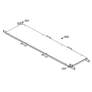
the connecting holes 337 of the connecting flanges 335, 536 at each of the
first end 331A
and second end 33113 of the joist 330 and further through any two
corresponding ones of
the openings 313, 314 of the hub 3.10. FIGS. 6.A and 613 particularly show one
of the
pins 340A employed at the first end 331A, it being understood that the same or
substantially same arrangement can be present at the end 33113. In this
manner, the
joist 330 can be connected in a virtually limitless number of ways, and
angles, to the
hub 310. For example, as shown particularly in FIGS. 6A and 68, one of the
pins 340A
can be placed in through the connecting flange 335A, through the opening 313A,
through
the connecting flange 336A (all at the first end 331A of the upper element
332), through
the connecting flange 33513, through the opening 314A, and then through the
connecting
flange 336D. In this scenario, the pin 340A further threads through connecting
holes
337A and 337.13.
100761 Also as shown (particularly see FIGS. 6A and 6B), each of the
pins 340A
additionally includes two roll pins 342 at its upper end. The lower of the two
roll pins
342 acts as a stop, thereby preventing the pin 340A. from slipping all the way
through the
joist 330 and hub 310. The upper roll pin 342 acts as a finger hold to allow
easy purchase
and removal of the pin 340.A from the joist 330 and hub 310. The design of
these various
parts is such that free rotation of both the joist 330 and hub 310 is allowed,
even while
the joist 330 and hub 310 are connected together. Rotational arrows R1 of
FIGS. 5 and
613 show the rotation of the joist 330 relative to the hub 310, while
rotational arrows R2
show the rotation of the hub 310 relative to the joist 330 of FIGS. 5 and 613.
These
17
CA 02912837 2015-11-17
WO 2014/189962 PCT/US2014/038832
rotational capabilities of the joist 330 and hub 310 relative to one another
provide, in part,
the articulating capability of the present design.
100771 Although articulation of the joist 330 and hub 310 relative to
one another
can occur in some embodiments or operational circumstances, in other
embodiments or
circumstances such articulation is precluded. In particular, articulation is
typically
precluded when the work platform system is fully implemented, or even when the
structural support components of the partly implemented support subsystem 130
are
installed as shown in FIG. 3. To preclude such articulation, as shown in FIGS.
6A and
68, optional locking pins 3408 (one of which is shown) are installed in
relation to the
interfacing hubs 310 and joists 330. More particularly as shown, locking of
the hub 310
and joist 330 of FIGS. 6A and 6B, so as to prevent relative articulation, is
achieved by
adding the locking pin 3408 through the locking holes 360A and 360D proximate
the end
331A of the joist 330. The locking pin 3408 particularly operates to preclude
such
articulation (at least in part) due to contact with the hub 310 along two of
several grooves
(or slots/dimples) 324 formed along the perimeters of the upper element 311
and lower
element 312 of the hub 310. Because the locking pin 3408 extends through two
of the
grooves 324, the locking pin effectively is prevented from moving around the
perimeters
of the upper and lower elements 311, 312 and correspondingly prevents such
movement
of the joist 330 relative to the huh 310.
j00781 As with the pin 340A, the locking pin 3408 cart include
additional two roll
pins 342 as shown, which serve the same purposes as discussed above with
respect to the
roll pins provided on the pin 340A. Although not shown in FIGS. 6A and 68, it
should
be likewise understood that another of the locking pins 3408 can similarly be
added
through the locking holes 360B and 360C proximate the end 3318 (see FIG. 5) of
the
joist 330 when that end is connected to another one of the hubs 3.10 by
another of the pins
340A.
00791 It should be appreciated that, in the present embodiment the
support
subsystem 130 employs components and features according to the QuikDeckrm
suspended access system available from Safway Services, Lie of Waukesha,
Wisconsin,
the beneficial assignee of the present patent application. As already
discussed, and as
further discussed below, these components of the support subsystem 130 among
other
18
81791999
things include the anchors 300, Intbs 310, and joists 330 and
related:subcomponents
discussed. above as well as the floor panels 732 and support chains 220
.further discussed
'below. Nevertheless, it should also be appreciated that a variety of other
support
subsystems and support subsystem components can also or instead be utilized
depending
upon the embodiment or circumstance, and such Other support subsystems and
associated
components are also intended to be encompassed. herein.
10080j Among other things, the present disclosure is particularly also
intended to
encompass support subsystems that employ other component(s) such as any of
those
described in. US. Patent No. 7,779,599 entitled "Articulating. Work Platkirm
Support
System, Work :Platform System, and Methods of Use Thereof', issued on August
24,
2010 (said issued patent being assigned to a.common assignee With the present
patent
application).. Also, for example, notwithstanding the above description of the
hubs
310, joists 330, and associated components shown in FIGS. 4, 5, 6A, and 613,
it should be appreciated that these components are only example components
that
can be employed among the components thrilling the underlying/internal
structural
support components (or "skeleton") of the support subsystem 130 and that other
stritctural support components can be employed in other embodiments. Further
for
example, depending upon the embodiment, the support subsystem 130 can include
a
variety of other components in addition to, andfor instead of, the anchors,
hubs, jOistsõ
floor panels, and support chains already discussed above.
10081j Additionally for example-, depending upon the embodiment,
various.
difterently-shaped components can be utilized. For example, while joists such
as the
joist 330 can be bar joists, the joists can also be open-web joists and/or
structural tubing,.
Further for example, one or more of the joists 330 can be made of multiple
pieces of
structural tubing shapes, or the joists 330 can be one single structural
tubing shape.
Similarly, the joist 330 could be made of Shaped steel (e.g., wide flange
elements, narrow
flange members, etc.), or other suitable shapes and materials. Also,
additionally other
types .ofjoists that are ourved rather than linear (straight) can be employed,
as can other
types of panel portions and supports for such panel portions. Further,
although in the
present embodiment it is envisioned that the first and second portions 132 and
134 of the
support subsystem 130 (including all hubs, joists, anchors, floor panels and
support
19
Date Recue/Date Received 2020-09-15
CA 02912837 2015-11-17
WO 2014/189962 PCT/US2014/038832
chains thereof) will be fully assembled and installed in relation to the
towers 140 prior to
any portions of the suspended subsystem (e.g., the partly implemented
subsystem 120)
being implemented, in alternate embodiments it is possible that portions of
the support
subsystem 130 will be implemented contemporaneously with, or subsequent to,
implementation of the suspended subsystem.
100821 Turning now to FIG. 7, a top plan, partly cross-sectional view of
an
assembly 700 of portions of a further implemented work platform system 710
corresponding to (that is, portions of the system which would be positioned
in) the region
150 of FIG. I is shown. The particular view provided by FIG. 7 is one taken
along line
7-7 of FIG. 12, which as discussed further below shows an additional enlarged
detail
view of a side elevation view of the assembly 700 in combination with portions
of the
suspension bridge 100 corresponding to the region 150 of FIG. 1. The further
implemented work platform 710 should be understood particularly to be the
partly
implemented work platform system .110 of FIGS. 1-3 as further modified to
include
additional components. in particular, the portions of the further implemented
work
platform system 710 shown in FIG. 7 include both the support subsystem 130
discussed
above as well as portions of a further implemented suspended subsystem 720,
which is
the partly implemented suspended subsystem 120 after being modified to include
additional components.
j0083) Although the support system 130 appears somewhat different in
FIG. 7 by
comparison with FIG. 3, this is merely because FIG. 7 now Shows panel sections
732 that
are supported upon the hubs 310 and joists 330 (the "skeleton) of the support
structure
that were shown and discussed in relation to FIG. 3. As already mentioned
above, the
panel sections 732 effectively provide a floor upon which work personnel can
walk and
on which equipment and components can be transported and supported.
Notwithstanding
this difference in appearance, it should nevertheless be understood that the
support
subsystem 130 of FIG. 7 is the same as that shown in FIG. 3, as well as the
same as that
shown in FIGS. 2 and 12, and thus particularly includes all of the hubs 310,
joists 330,
and anchors 300 shown in FIG. 3 as well as the panel sections 732 and the
support chains
220 shown and discussed in relation to FIGS. 2 and 12. It should additionally
be
understood that, although the support subsystem 130 is considered be a fully
CA 02912837 2015-11-17
WO 2014/189962 PCT/US2014/038832
implemented or installed support structure for the present embodiment, in
other
embodiments additional components not shown in FIG. 7 (or in FIGS. 2, 3, or
12), such
as railings, can still be added to the support subsystem .130 and that the
support
subsystem would only be complete after such additional components are
implemented.
100841 With respect to the further implemented suspended subsystem 720,
as
shown in FIG. 3 this suspended subsystem differs from the partly implemented
suspended subsystem 120 of FIG. 3 particularly insofar as the subsystem 720
includes
multiple panel sections 750 that have been installed so as to be supported
upon the
various pairs of wire tendons 230. More particularly as shown, given the
presence of the
nine pairs of wire tendons 230 (that is the pairs of wire tendons 301, 302,
303, 304, 305,
306, 307, 308, and 309), there are shown to be eight partly completed rows of
the panel
sections 750, namely, first, second, third, fourth, fifth, sixth, seventh, and
eighth rows
751, 752, 753, 754, 755, 756, 757, and 758, where each respective one of the
rows (e.g.,
751, 752, etc.) is supported upon a corresponding pair of successive ones of
the pairs of
the wire tendons 230 (e.g., the pairs 301 and 302, the pairs 302 and 303,
etc.). It should
be appreciated that the actual number of rows of panel sections 750, as well
as the actual
number of pairs of wire tendons 230, can vary depending upon the embodiment.
For
example, in some other embodiments, there is only a single row of the panel
sections 750
positioned on and between two pairs of the wire tendons 230, while in other
embodiments, there can be more than or less than eight rows of panel sections
and more
than or less than nine pairs of wire tendons.
100851 Turning now to FIGS. 8A, 9, and 10, a top plan view, side
elevation view,
and right end side elevation view of an example one of the panel sections 750
of FIG. 3
are respectively shown. For example, FIGS. 8A, 9, and 10 can be considered to
show a
panel section 765 shown in FIG. 3, which is the rightmost panel section of the
sixth row
756 of panel sections, and which can be considered identical to each of the
other panel
sections 750 shown in FIG. 3. As illustrated, the Nine! section 765 is
generally in the
shape of an elongated rectangle, and in the present embodiment has a width
dimension
759 of 92 inches (or about eight. feet) and a length dimension 761 of 24
inches (two feet),
For purposes of the present discussion, the width dimension 759 corresponds
substantially to the distance between neighboring ones of the pairs of wire
tendons,
21
CA 02912837 2015-11-17
WO 2014/189962 PCT/US2014/038832
between whiCh the panel section 765 extends, and the length dimension 761 by
contrast
corresponds to the length of the panel section 765 along the wire tendons
(albeit in other
embodiments length and width dimensions can be defined difTerently).
100861 In other embodiments, these dimensions of any one or more oldie
panel
sections that are employed in a given suspended subsystem can vary from those
shown
with respect to the panel section 765. For example, in another embodiment, the
panel
section can be approximately eight feet long by one fwt wide. indeed, the
panel section
need not be an elongated rectangle but also could be another shape, such as
that of a
square. Additionally, although not shown in FIG. 7, in some embodiments
different
panel sections having different sizes (and/or shapes) can be implemented in
the same
work platform system. For example, certain, of the panel sections can have the
two feet
by eight feet dimensions stated above, and others of the panel sections in the
same work
platform system can have one foot by eight feet dimensions. Through the use of
panel
sections of varying dimensions (e.g., different length and/or width
dimensions), a variety
of practical issues associated with the implementation of the work platform
system can be
conveniently addressed. For example, if one or more obstacles (e.g., a pipe
jutting
beneath the deck 22) precludes the implementation of one of the panel sections
750 along
one of the rows of panel sections, it can still potentially be possible for a
panel section of
a different size to be implemented instead.
100871 As an example, the panel section 765 particularly includes a top
panel
surface 763 having dimensions that are equal to the previously-mentioned width
and
length dimensions 759 and 761 of the overall panel section 765, and that is
the surface
upon which work personnel can walk. In the present embodiment, the top panel
surface
763 is made of wood (e.g., plywood). Use of wood as the top panel surface 763
can be
particularly advantageous in that surface provides better traction even during
conditions
where moisture exists on the surface (e.g., during a rainstorm) than if other
materials such
as sheet metal were used. Nevertheless, the particular material employed to
form the top
panel surface 763 can vary depending upon the embodiment.
100881 Further with respect to the panel section 765, the top panel
surface 763 is
mounted upon steel tubes or struts 760, which are shown in each of FIGS. 8A,
8B, 9, and
(the struts are shown in phantom particularly in FIGS. SA and 813), and which
form a
22
CA 02912837 2015-11-17
WO 2014/189962 PCT/US2014/038832
support structure or "skeleton" underlying the panel surface 763. Additionally
as shown,
the struts 760 particularly include a pair of side struts 762, a pair of end
struts 764, and a
supporting strut(s) 766. The side struts 762 and end struts 764 effectively
form a loop
that follows along the perimeter of the panel surface 763, with the side
struts 762
extending the full length of the width dimension 759 and the end struts 764
extending the
full width of the length dimension 761. The supporting strut(s) 766 is
positioned
underneath the panel surface 763 so as to extend between the two side struts
762.
100891 As shown in FIG. 8A, the struts 760 forming the underlying
support
structure (i.e., side struts 762, end struts 764 and supporting struts 766)
can have the same
shape, thickness and inner and outer dimensions. In other embodiments, struts
760 can
have different shapes, thicknesses, and outer and inner dimensions. For
example, in one
embodiment, the side struts 762 and end struts 764 can be square tubular steel
while
supporting struts 766 can be rectangular tubular steel,
100901 In the embodiment shown in FIG. 8A, the panel section 765
contains a
single supporting strut 766 positioned midway between the end struts 764. In
the
embodiment shown in FIG. 88, the panel section 765 contains two supporting
struts 766
evenly positioned between end struts 764. As illustrated through 'FIGS. 8A and
8B, more
or fewer supporting struts 766 can be used to support the panel surface 763,
and the
number and positioning of supporting struts 766 can depend on the material,
weight,
strength and/or thickness of panel surface 763. For example, in one
embodiment, a single
supporting strut 766 can be used with a panel surface 763 having a V2-inch
thickness,
while two supporting struts 766 can be required with a panel surface 763
having a 3/8-
inch thickness.
100911 In addition to the top panel surface 763 and the struts 760, the
panel
section 765 additionally includes several support components that extend
outward from
the struts 760 and allow for the mounting of the panel section 765 in relation
to the wire
tendons 230 and also in relation to other ones of the panel structures 750 as
shown in
FIG. 7 (e.g., so as to form the rows of panel sections). More particularly as
Shown, these
support components include four wire tendon support extensions 770 as well as
four
handle support extensions 780, all of which extend outward beyond the confines
of either
the width and length dimensions 759 and 761 mentioned above. As shown, the
wire
23
CA 02912837 2015-11-17
WO 2014/189962 PCT/US2014/038832
tendon support extensions 770 particularly extend outward away from the end
struts 764,
that is, outward along directions that are parallel or substantially parallel
to the width
dimension 759. Two of the wire tendon support extensions 770 extend outward
generally
at opposite ends of one of the side struts 762, and the other two of the wire
tendon
support extensions 770 extend outward generally at opposite ends of the other
of the side
struts 762. By contrast, the handle support extensions 780 extend outward from
the side
struts 762 in directions parallel or substantially parallel to the length
dimension 761, and
are all positioned at locations well inward of the end struts 764.
100921 As is evident from FIGS. 8A and 8B, the wire tendon support
extensions
770 include small bends 774 such that outer portions 776 of the extensions 770
are
shifted slightly relative to inner portions 778 by which the extensions 770
are affixed to
the end struts 764. More particularly, in the present embodiment, each of the
wire tendon
support extensions 770 extending from a first one of the end struts 764 (e.g.,
the right end
strut shown in FIG. 8A) has a. respective outer portion 776 that is offset or
shifted in a
first direction along the length dimension 761, and each of the wire tendon
support
extensions 770 extending from the other one of the end struts 764 (e.g., the
left end strut
shown in FIG. 8A) has a respective outer portion 776 that is offset or shifted
in a
direction opposite that of the first direction. Such oppositely-directed
offsets (or
"joggles") of the outer portions 776 that are at opposite ends of the panel
section 765 are
complementary so as to Make it possible for two of' the panel sections 750 in
neighboring
ones of the rows (e.g., two panel sections that are respectively positioned,
side by side, in
the rows 756 and 757 of FIG. 7) to be supported upon a shared pair of the wire
tendons
230 (e.g., by the pair of wire tendons 307) and also to be aligned such that
the
corresponding side struts 762 of each of the panels sections are exactly
aligned with one
another. Thus, in FIG. 7, the rows 751, 752, 753, 754, 755, 756, 757, and 758
of the
panel sections 750 are shown to be completely aligned with one another.
100931 Further as illustrated, particularly in FIG. 9, each of the wire
tendon
support extensions 770 and particularly the outer portions 776 thereof
includes a pair of
indentations 772 that extend upward from a bottom ridge of those portions. It
is by virtue
of these indentations 772 that the outer portions 776 of the wire tendon
support
extensions 770 can be slipped over and onto the two pairs of wire tendons 230
between
24
CA 02912837 2015-11-17
WO 2014/189962 PCT/US2014/038832
which the panel 750 is to be positioned. Thus, for example, continuing to
assume that the
panel section 750 of FIGS. 8A, 8B, 9, and 10 is the panel section 765 of FIG.
7 that is the
rightmost one of the panel sections of the sixth row of panel sections 756,
then the
indentations 772 oldie leftward one of the outer portions 776 shown in FIG. 9
can be
considered to be the indentations that receive (slip over) the pair of wire
tendons 307, and
the indentations 772 of the rightward one of the outer portions 776 shown in
FIG. 9 can
be considered to be the indentations that receive (slip over) the pair of wire
tendons 306.
100941 In addition to the above features, it will be observed from FIG.
9 that in
the present embodiment each of the wire tendon support extensions 770 also
includes an
orifice or notch 781, positioned generally in between the indentations 772 of
the
respective wire tendon support extension. By virtue of the presence of the
orifices 781 of
the wire tendon support extensions, in some embodiments, additional structures
such as
guard rail posts or wires or other structures (not shown) can be affixed to
the wire tendon
support extensions and thus to the remainder of the suspended subsystem.
100951 Notwithstanding the above discussion concerning the wire tendon
support
extensions 770, it should be appreciated that those extensions (or similar
structures
employed to allow the panel sections 750 to be supported upon flexible support
elements
such as the wire tendons 230) can take on different forms in other
embodiments. For
example, in some alternate embodiments, the wire tendon support extensions do
not have
any offsets (or "joggles"). That is, in such embodiments, the wire tendon
support
extensions are straight such that the inner and outer ends (that is, the
portions of the wire
tendon support extension corresponding to the inner and outer portions 778 and
776
discussed above) are aligned. The offsets (or "joggles") need not be employed
in all
embodiments, since the thickness of the wire tendon support extensions can be
small, and
since there is not always any particular need that panel sections provided in
rows on
opposite sides of a given pair of wire tendons be fully aligned (that is, so
that the side
struts 762 of panel sections in different rows are lined up).
100961 Further in some alternate embodiments one or more subleatures of
one or
more the wire tendon support extensions can take a form different than those
discussed
above with respect to FIGS. 8A, 8B, 9, and 10. For example, in one alternate
embodiment, one or more of the wire tendons support extensions of a panel
section can
CA 02912837 2015-11-17
WO 2014/189962 PCT/US2014/038832
take the form of a wire tendon support extension 770.A shown in FIG. 9A, which
for
comparison purposes is shown to correspond to a portion of one of the wire
tendon
support extensions 770 of FIG. 9. in this example, rather than having the two
indentations 772 that are identical in shape, instead the wire tendon support.
extension
770A has a first indentation 772A and a second indentation 77213 that are
somewhat
different in shape, with the second indentation 772B identical or
substantially identical to
the indentations 772 of FIG. 9 but the first indentation 772A having an
additional cutout
region 783A expanding the indentation beyond the size and shape of the
indentations 772
of FIG. 9. The expanded size of the first indentation 772A with the additional
cutout
region 783A allows, in at least some embodiments, easier mounting of the wire
tendon
support extension 770A onto pairs of wire tendons such as the wire tendons
230. Also it
can be noted that, in the alternate embodiment of FIG. 9A, the wire tendon
support
extension 770A includes an orifice 781A corresponding to the orifice 781 of
one of the
wire tendon support extensions 770 of FIG. 9 except insofar as the orifice
781A is
positioned lower and closer to the second indentation 772B than to the first
indentation
772A (at least when compared to the uppermost tips of the two indentations) to
accommodate the presence of the additional cutout region 783A of the first
indentation
772A. Notwithstanding the above description concerning FIGS. 9 and 9A, it
should be
understood that the wire tendon support extensions can be modified in other
manners as
well. For example, in some additional embodiments, additional holes (e.g. in
addition to
the orifice 781 or orifice 781.A can be added to facilitate fixturing and/or
for use on
scaffold arrangements of other sizes).
100971 Referring still to FIGS, 8A, 813õ 9õ and 10õ the handle support
extensions
780 take a different structural form than the wire tendon support extensions
770 insofar
as each of the extensions 780 is a looping structure that extends outward away
from one
of the side struts 762 (outward away from the top panel surface 763), then
extends
sideways generally parallel to the side struts so as to form a respective
intermediate
handle portion 779, and then loops back so as to connect up again with the
respective side
strut .from which it originally extended (at a different location along that
side strut). In
this sense, each of the handle support extensions 780 is a U-shaped extension.
Further as
evident from FIG. 10, when the panel section 765 is viewed from the right end
side (or
26
CA 02912837 2015-11-17
WO 2014/189962 PCT/US2014/038832
the left end side), it becomes apparent that each of the handle support
extensions 780 not
only is U-shaped but. also has an L-shaped characteristic. More particularly
as shown,
each of the handle support extensions 780 juts outward from the respective
side strut 762
on which it is mounted, in a generally horizontal manner (that is, parallel to
the top panel
surface 763), but then extends further to include a hook-like formation 785,
at which the
respective handle support extension first dips down (that is, away from the
top panel
surface) slightly and then curves back upward (that is, toward the plane of
the top panel
surface) to a location at which the intermediate handle portion 779 of the
extension is
formed, In the present embodiment, the respective intermediate handle portions
779 of
the respective handle support extensions 780 are at respective locations that
are
substantially higher than the respective locations at which the respective
handle support
extension 780 first extend horizontally outward.
100981 The particular hook-shaped configuration of the handle support
extensions
780 of each of the panel sections 750 such as the panel section 765 serves
several
purposes. To begin, shape of the handle support extensions 780 allows those
extensions
to serve as handles by which work personnel (or other installation equipment)
can grasp
and support (and thus lift and move) the panel sections 750 during
implementation of the
work platform system. Additionally, the shape and positioning of the handle
support
extensions 780 (as discussed further below) allows for adjoining ones of the
panel
sections 750 in any given row of the panel sections to be easily positioned in
relation to
one another and ultimately interlocked with one another. Indeed, due to this
interlocking
of panel section sections of a given row afforded by the handle support
extensions 780, in
combination with the weight of the panel sections themselves, the panel
sections 750 in
the present embodiment can generally be supported and mounted onto the pairs
of wire
tendons 230 (with the indentations 772 receiving the pairs of wire tendons)
without any
additional securing mechanisms that would tend to preclude lifting of the
panel sections
off of the wire tendons. That is, the panel sections 750, once in place, are
not positively
locked to the wire tendons but merely remain in place relative to those
tendons because
of their weight and their interconnections with neighboring panel sections.
That said, it
should also be appreciated that, in alternate embodiments, the panel sections
750 can
27
CA 02912837 2015-11-17
WO 2014/189962 PCT/US2014/038832
include other features by which the panel sections are positively locked or
secured to the
pairs of wire tendons on which those panel sections are supported.
100991 Further in regard to the installation and interlocking of the
panel sections
750 such as the panel section 765, FIGS. 11A, 11B, and 11C respectively
provide first,
second, and third partially cutaway schematic views of an additional panel
section 791
(which is of the same type as each of the panel sections 750) being installed
in relation to
the panel section 765 that has already been positioned onto the wire tendons
230 (e.g., on
to the sixth and seventh pairs 306 and 307 of the wire tendons), so that the
additional
panel section 791 likewise is positioned onto and supported by those wire
tendons. More
particularly, each of FIGS. 11A, I1B, and 11C is a cross-sectional view that
is taken
through both of the panel sections 765 and 791, along a line that corresponds
to a line 11-
11 shown in FIG. 8 with respect to the panel section 765, where as shown in
FIG. 8 the
line 11-11 cuts through one of the handle support extensions 780 of the panel
section 765
that is along that one of the side struts 762 of that panel section adjacent
to which the
additional panel structure 791 is to be placed. Further in this regard, it
should be
understood that, although FIG. 8 does not show also the additional panel
section 791, the
cross-sectional view that is provided in FIGS. 11A, 11B, and Ii C is that
which would be
appropriate given a typical installation process of the additional panel
section 791 in
relation to the panel section 765 in Which the end struts 764 of the two panel
sections are
aligned with one another.
1001001 More particularly, FIG. I IA shows how, when the additional panel
section
791 is first being installed in relation to the panel section 765, the
additional panel section
791 is first positioned (e.g., by work personnel lifting the panel section 791
into place
using the handle support extensions 780) so that the top panel surface 763 of
the
additional panel section 79.1 is received into and extends substantially
vertically upward
from the two co-aligned handle support sections 780 of the panel section 765.
When
positioned in this manner, a first of the side Struts 762 of the additional
panel section 791
is positioned into the hook formations 785 of the handle support extensions
780 of the
first panel section 765 into which the additional panel section 791 has been
received.
Also, in this initial position, the top panel surface 763 extends downward to
the handle
support extensions 780 of the panel section 765 (or almost to those handle
support
28
CA 02912837 2015-11-17
WO 2014/189962
PCT/US2014/038832
extensions) and extends in between the neighboring side struts 762 of the
panel sections
765 and 791).
10010.11 Turning to
FIGS. I I B and I IC, respectively, upon the additional panel
section 791 being positioned into place relative to the panel section 765 as
shown in FIG.
11A, then further installation of the additional panel section 791 occurs by
rotation of that
panel section 791 in a direction generally indicated by an arrow 792 of FIG.
I1B, that is,
rotation generally downward and outward away from the panel section 765, up
until such
time as the additional panel section 791 is fully in place such that the top
panel surface
763 of that panel section is horizontal and parallel to the top panel surface
763 of the
panel section 765. When such rotational movement is fully completed, it will
be
appreciated that both of panel sections 765 and 791 are then supported upon
the wire
tendons 306 and 307 between which those panels both extend, by way of the wire
tendon
support extensions 770 formed on each of those panels (as discussed above with
respect
to FIGS. 8 and 9). Also, upon full installation, the neighboring side struts
762 of the
panel sections 765 and 791 generally adjoin one another.
1001021 It will he
appreciated that, to allow for proper rotation of the additional
panel section 791 relative to the panel section 765, the handle support
extensions 780
necessarily extend outward away from the side strut 762 of the first panel
section 765 on
which those handle support extensions are mounted by a distance that is
somewhat in
excess of the cross-sectional width of the side struts 762 of the additional
panel section
79.1, with such an excess distance being shown in FIG. I IC as a distance 794.
It will
further be appreciated that, following proper and full installation, panel
section 765
assembled in side-by-side relation will be at least partially restricted in
movement in at
least one of the side-to-side and up-and-down directions, more preferably in
both the
side-to-side and up-and-down directions, as a result of the interconnection of
handle
support extensions. Handle support extensions, in combination with tendon
support
extensions 770 (not shown), therefore at least partially, preferably
completely, limit
movement of fully installed panel sections in side-by-side relation in all
three axes of
movement, that is, side-to-side, up-and-down, and front-to-back.. In some
embodiments,
therefore, panel sections 765 are secured to tendons and each other without
the necessity
of additional locks or securing structures, mechanisms or devices.
29
CA 02912837 2015-11-17
WO 2014/189962 PCT/US2014/038832
1001031 Further as shown in FIG. 1 IC (although not shown in FIGS. 1 IA
and
1113), the additional panel section 791 includes handle support extensions 780
just as
does the panel section 765. Given that the spacing of the handle support
extensions 780
on each of the panel sections 765, 791 is the same as that shown in FIG. 8
(which is
representative of the features of each of the panel sections 750 including the
panel
sections 765 and 791), it should be recognized that the handle support
extensions 780 on
one oldie side struts 762 of each of the panel sections 750 are offset in a
first direction,
relative to the middle strut 766 of the respective panel section, but that the
handle support
extensions 780 on the opposite one of the side struts 762 of the respective
panel section
750 are offset from the middle strut in the opposite direction. That is, the
handle support
extensions 780 along the top one of the side struts 762 as shown in FIG. 8 are
offset to
the right while the handle sections along the bottom one of the side struts
762 are offset
to the left. More particularly, in the present example embodiment of the panel
section
765 as shown in FIG. 8, the leftmost portion of the left handle support
extension 780
extending from the upper one of the side struts 762 is offset thirty-two
inches from the
left side edge of that panel section, which is also the left side edge of the
left one of the
end struts 764, and the leftmost portion of the right handle support extension
780
extending from that side strut is offset over another twenty-eight inches from
the leftmost
portion of that left handle support extension. By contrast, the rightmost
portion of the
right handle support extension 780 extending from the lower one of the side
struts 762 is
offset thirty-two inches from the right side edge of that panel section, which
is also the
right side edge of the right one of the end struts 764, and the rightmost
portion of the left
handle support: extension extending from that side strut is offset over
another twenty-
eight inches from the rightmost portion of that right handle support
extension.
1001041 Given this arrangement of the handle support extensions 780 on
each of
the panel sections 750, it should be appreciated that the handle support
extensions 780 of
each of the panel sections 750 are substantially complement-my. That is, due
to the
oppositely-shifted arrangements of the handle support extensions 780 on
opposite sides
of each of the panel sections 750, neighboring panel sections can be
positioned next to
one another in a manner in which, instead of the handle support extensions 780
of the
neighboring panel sections encountering and obstructing one another, the
handle support
CA 02912837 2015-11-17
WO 2014/189962 PCT/US2014/038832
extensions 780 of each of the neighboring panel structures serves to engage or
mesh with
the other of the neighboring panel structures. For example, when one of the
panel
sections 750 such as the additional panel section 791 is implemented in
relation to
another of the panel sections such as the panel section 765 as shown in FIG. I
IC, the
handle support extensions 780 on the side of the panel section 765 facing the
additional
panel section 791 extend under and up and around the adjoining side strut 762
of the
additional panel section 791, and likewise the handle support extensions 780
on the side
of the panel section 791 facing the panel section 765 (as shown in phantom in
FIG. 11C)
extend under and up and around the adjoining side strut 762 of the panel
section 765.
1001051 Although the panel section 765 shown in FIGS. 8, 9, and 10 and
again in
FIGS. 11A, 111.1, and I IC is one example type of panel section that can be
employed in a
suspended subsystem such as the further implemented suspended subsystem 720,
as
already discussed it Should be appreciated that depending upon the embodiment
or
circumstance numerous types of panel sections having many different types of
features
can be employed. In addition to variations in the overall sizes, dimensions,
or shapes of
the panel sections that are employed, which can vary with the particular
suspended
subsystem and even vary in the context of a given suspended subsystem, it is
also
possible for features of the panel sections such as the handle support
extensions to vary as
well. FIGS. 11D, 11E, 11F, 11G, 1111, 111, lU, 11K, I 1L, and 11M are several
examples of alternative panel sections 850, 856, 860, 870, 880, 885, 888, and
890 having
certain features differing from those of the panel section 765. More
particularly, as
shown, in these example embodiments, each of the alternative panel sections
includes
wire tendon support extensions 770 substantially identical to those of the
panel section
756, but instead have different types or arrangements of handle support
extensions and/or
complementary components for interfacing handle support extensions.
1001061 More particularly in this regard, referring to FIG. 11D, a
perspective view
is provided of the alternative panel section 830, which is substantially
identical to the
panel section 765 except insofar as, although the alternative panel section
850 includes a
pair of the handle support extensions extending from a first side 852 of the
alternative
panel section, no other handle support extensions are provided on the opposite
side 854
of the alternative panel section. Additionally, rather than employing the
hooked type of
31
CA 02912837 2015-11-17
WO 2014/189962 PCT/US2014/038832
handle support extensions 780 present in the panel section 756, the
alternative panel.
section 850 employs handle support extensions 851. that differ from the handle
support
extensions in that the handle support extensions merely extend outward from
the side 852
horizontally and then experience an upward 90 degree bend, as is shown
particularly well
in FIG. 1.1G, which is discussed further below.
1001071 Further, referring to FIG. 11E, a perspective view is provided of
the
alternative panel section 856, which is substantially identical to the
alternative panel
section 850 except insofar as, although the alternative panel section 856
includes a pair of
the handle support extensions 851, one (rather than two) of those handle
support
extensions is provided on a first side 858 of that alternative panel section
and the other of
those handle support extensions is provided on an opposite side 859 of that
alternative
panel section. Additionally, referring to FIG. 11F, a perspective view is
provided of the
alternative panel section 832, which is substantially identical to the
alternative panel
section 856 except insofar as the alternative panel section 832 only includes
a single one
of the handle support extensions 851 along a first side 861 (positioned
generally at the
middle of that side), but no handle support extension along an opposite side
864.
1001081 Although the type, number, and positioning of the handle support
extension(s) 851 in each of the alternative panel sections 850, 856, and 832
varies from
that of the panel section 756, it should be appreciated that the handle
support extension(s)
in each of these alternative panel sections still can perform to at least some
extent the
functions performed by the handle support extensions 780 in the panel section
756 (and
the panel section 791) as illustrated in FIGS. 11A, 11B, and I IC. The handle
support
extension(s) 851 can still be used for carrying and moving of the alternative
panel
sections 850, 856, and 832 (as shown in FIGS. I ID- I 1(i). Also, the handle
support
extension(s) 851 can further serve (at least to some extent) to orient,
capture and support
adjacent panel sections. For example, as illustrated in FIG. 11G, which
illustrates in a
cross-sectional, partly cutaway view two of the alternative panel sections 850
of FIG.
I ID in an assembled positioned adjacent to one another side-by-side (as if in
a row of the
panel sections), it is still the case in such an embodiment that the handle
support
extensions 851 extending from the opposite side 852 of one of those
alternative panel
sections will extend under, up, and around a neighboring side strut 862 of the
other of
32
CA 02912837 2015-11-17
WO 2014/189962 PCT/US2014/038832
those alternative panel sections 832, and thus serve to at least partly hold
in place and
support that other panel section.
1001091 Further, with respect to FIG. 11H, the alternative panel section
870 by
contrast with the alternative panel section 850 of FIG. I ID includes a pair
of handle
support extensions 872 extending from a first side 874 that, in contrast to
the handle
support extensions 851, have no bends at all but rather merely are U-shaped
structures
extending out purely horizontally from the first side 874. Additionally, on an
opposite
side 878 of the alternative panel section 850, rather than having any handle
suppon
extensions of any type, instead that alternative panel section includes a pair
of
complementary interlocking devices or protrusions 876. As shown, each of the
respective interlocking devices 876 is aligned, along the opposite side 878,
with a
respective one of the handle support extension 872 positioned on the first
side 874, and
the interlocking devices 876 are sized and configured so that protruding
portions of the
interlocking devices will respectively fit within complementary interior
orifice regions of
the handle support extensions 872 of another one of the alternative panel
sections 870
when two such alternative panel sections are assembled.
1001101 Such an arrangement is shown in FIG. I it, which provides a side
elevation view of two of the alternative panel sections 870 of FIG. 11H
positioned
adjacent to one another side-by-side (as if in a row of the panel sections).
As illustrated,
the interlocking devices 876 along the opposite side 878 of one of the
alternative panel
sections 870 are received within, and extend through and beneath, respective
ones of the
handle support extensions 872 positioned on the first side 874 of another of
the
alternative panel sections. Given such positioning of the interlocking devices
876 within
the handle support extensions 872, the two alternative panel sections 870 are
interconnected with one another. Further, as with the handle support
extensions 780 and
851, the handle support extensions 872 again serve both as handles to
facilitate carrying
and moving of the alternative panel sections 870, but also serve to support
the adjacent
alternative panel section. For example, as illustrated in FIG. l II, the
handle support
extensions 872 receiving the interlocking devices 876 also extend beneath a
neighboring
side strut 879 of the alternative panel section associated with those
interlocking devices.
33
CA 02912837 2015-11-17
WO 2014/189962 PCT/US2014/038832
1001111 Although the alternative panel section 870 shown in FIGS. 111-{
and 111 is
one example of an alternative panel section employing the handle support
extensions 872
that are flat, the alternative panel sections 880, 885, 888, and 892
respectively shown in
respective FIGS. 113, IIK, I IL, and I 1M are additional examples in this
regard. In
contrast to the alternative panel section 870, however, none of the
alternative panel
sections 880, 885, 888, and 892 include any of the interlocking devices 876.
More
particularly, FIG. 1.111 shows a perspective view of the alternative panel
section 880, and
shows that panel section as having only one of the handle support extensions
872
extending from a first side 882 (generally from. a middle location along that
side) but
having no other handle support extension 872 extending from an opposite side
883. By
contrast, FIG. IIK shows the alternative panel section 885 as having one of
the handle
support extensions 872 extending from a first side 884 and another of the
handle support
extensions 872 extending from an opposite side 886, FIG. M. shows the
alternative
panel section 888 as having two of the handle support extensions 872 extending
from a
first side 887 but no handle support extensions extending from an opposite
side 889, and
FIG. I 1M shows the alternative panel section 892 as having two of the handle
support
extensions 872 extending from a first side 890 and another two of the handle
support
extensions 872 extending from an opposite side 894.
1001121 it should be appreciated that, as with the handle support
extensions 780 of
the panel section. 756, the pairs of the handle support extensions 872
extending from the
first and opposite sides 892 and 894 of the alternative panel section 890 of
FIG. 1 IM are
offset from one another along the lengths of those respective sides, so as to
be
complementarily positioned to facilitate the positioning of multiple ones of
the alternative
panel sections 890 side-by-side. Likewise, as with the handle support
extensions 851 of
the alternative panel section 856 of FIG. 11E, the handle support extensions
872 of the
alternative panel section 885 ofFIG. 11K are offset from one another along the
lengths of
the sides 884 and 886 so that the handle support extensions on the opposite
sides are
positioned complementarily,
10011.31 Turning now to FIGS. I IN, 110, 11P, .11Q and 11 R, a further
alternative
panel section 1000 is shown. Alternative panel section .1000 includes gravity
latch 1010.
Gravity latch 1010, shown in the up position in FIGS. 1IN and 110, is joined
with
34
CA 02912837 2015-11-17
WO 2014/189962 PCT/US2014/038832
tendon extensions 770 at pivot point 1015. Gravity latch 1010 includes a
tendon-
engaging portion 1012 configured to directly or indirectly engage tendons 230
when in a
down position as shown in FIGS. 11P and 11Q, and extension 1013 with securing
aperture 1014 and upper surface 1016. In the exemplary embodiment illustrated,
tendon-
engaging portion 1012 has a C-shape or configuration.
[00114) Gravity hook 1010 is specifically designed with a center of
gravity A
which is just offset from pivot point 1015 when in both the up position and
down
position, as illustrated in FIGS. I IP and 11Q. in FIGS. 110 and 11R, the
center of
gravity A is indicated using a circular marking solely to reference the area
A.
Embodiments of gravity hook 10.10 may or may not include a visible or physical
indication of the center of gravity.
1001151 Because the center of gravity A is offset from pivot point 1015
when in
both the up and down positions, gravity hook 1010 will stay in the up position
until hook
1010 is physically rotated such that the center of gravity A passes to the
other side of
pivot point 1015. Similarly, gravity hook 1010 will stay in the down position
until hook
1010 is physically rotated such that the center of gravity A passes back over
pivot point
1015. Gravity hook 1010 therefore acts to prevent upward movement of panel
sections
750 relative to tendons 230.
1001161 Aperture 1014 of extension 1013 is configured to correspond to
aperture
1017 of tendon extension 770. For added stability, a securing component, such
as a zip-
tie, bolt, or other structure, can be secured through apertures 1014, 1017,
thereby
physically connecting gravity hook 1010 and tendon extension 770 at a second
point, the
first being pivot point 1015. Similarly, notch 1018 of tendon extension 770 is
configured
to correspond to the location of upper surface 1016 when gravity hook is the
down
position, allowing an additional cover structure (discussed below) to be
installed between
panel sections 750 over gravity hook 1010. Notch 1018 also allows access to
upper
surface 1016 to pivot gravity hook 1010 from a down position to an up
position.
1001171 For example, as illustrated in FIGS. 11N, 110, 11P and I IQ,
upper
surface 1016 is configured to provide a graspable area or contact area for
manipulating
gravity hook 101Ø For example, when in the up position, upper surface. 1016
can be
pushed, such as with a toe strike or by hand, to pivot, gravity hook 1010 to
its down
CA 02912837 2015-11-17
WO 2014/189962 PCT/US2014/038832
position. When in the down position, upper surface 1016 protrudes above notch
1018 so
that gravity hook 1010 can be returned to its up position such as by
manipulating the
hook 1010 by foot or grasping upper surface 1016 by hand.
1001181 FIG. 11R illustrates the gravity hook 1010 in further detail. As
shown in
FIG. IR, tendon engaging portion 1012 includes an inclined surface 1020. Under
uplift
conditions (i.e., under tendon pull force 1030), angled surface 1020 causes
gravity hook
1010 to rotate clockwise (relative to the view shown in FIG. 11R), thereby
keeping the
gravity hook 1010 in a closed position.
1001191 The location of the center of gravity A and pivot point 1015 also
serves to
keep gravity hook 1010 closed under uplift conditions. Specifically, in the
closed
position, center of gravity A is offset from the center of pivot point 1015 at
a distance of
1024 and also set below the center of pivot point 1015. The position of the
tendon 230 is
also offset from the center of pivot point 1015. As a result, under uplift
conditions (i.e.,
under tendon pull force 1030), gravity hook 1.010 is rotated in a clockwise
position and
remains closed.
1001201 It should be appreciated that the panel section 1000 described
above can
have any configuration of handle support extensions as discussed herein.
Additionally, it
should be appreciated that the examples of alternative panel sections
discussed above are
merely examples and that numerous other variations of panel sections can be
implemented in embodiments encompassed by the present disclosure.
10012111 FIGS. I IS and 11T illustrate modified tendon extension 770a' and
770b'
for use with panel 1000 and gravity latch 1.010. Modified tendon extensions
770a' and
770b' provide support and stability when stacking unassembled panel sections
1000. As
illustrated in FIGS. I IS and I IT, modified tendon extensions 770a' and 770b'
include
contoured portions. 771b, making tendon extension 770a' distinctly a right-
side tendon
extension and tendon extension 770b' distinctly a left-side tendon extension.
In other
words, tendon extensions 770a' and 770b' are mirror images of each other.
1001221 FIG, I IT shows modified tendon extension 770a' in more detail.
As
shown, contoured portion 7711, angles away from the body 771a of tendon
extension
770a' and the plane of the panel section 1000. When panel sections 1000 are
stacked on
top of one another (such as tbr storage or transport, for example), respective
right and left
36
CA 02912837 2015-11-17
WO 2014/189962 PCT/US2014/038832
tendon extensions 770a', 770b' on adjacently stacked panel sections engage
each other in
an overlapping fashion to prevent or limit movement (e.g., side-to-side
movement) of the
panels 1000 during storage and transport.
1001231 FIG. 11U shows an alternative embodiment of a gravity latch
1010'.
Gravity latch 1010' functions the same as described with reference to FIGS.
11N-11 R,
but has a more hook-shaped tendon engaging portion 1012'. In some embodiments,
as
shown in FIG. 11U, gravity latch 1010' includes receiving aperture 1019' for
engaging a
protuberance and a toe board.
1001241 Returning to FIG. 7 and further turning to FIGS. 7A and 78, full
implementation of the suspended subsystem includes not only implementing the
panel
sections 750 onto the wire tendons 230, but also involves implementation of
additional
components as well. To illustrate these additional components, FIG. 7A
provides a detail
view of a region 961 of FIG. 7 particularly focused upon a location at Which
several of
the panel sections 750 of each of two neighboring rows of the panel sections
751 and 752
are supported upon an intermediate pair of the wire tendons 230, namely, the
wire
tendons 302. Further, FIG. 78 is also provided to show the same region (region
961) as
shown in FIG. 7A, as that region would be seen from underneath (that is, FIG.
7A is a top
plan view of the region 961 while FIG. 78 is a bottom plan view of that region
or
substantially the same region).
1001251 From FIGS. 7A and 7B, it. should particularly be evident that,
due to the
configuration of the panel sections 750 and the wire tendon support extensions
770, the
top panel surfaces 763 of the panel sections do not cover over the supporting
wire
tendons 302, but rather there is a space or gap between the top panel surfaces
of the panel
sections 750 of neighboring rows of the panel sections such as the rows 751
and 752.
Given the presence of these gaps between the top panel surfaces 763 of
neighboring rows
of the panel sections 750 such as the panel sections of the rows 751 and 752,
in the
present embodiment additional cover structures (or gap fillers) 767 are
provided
subsequent to the implementation of the panel sections onto the wire tendons
2.30, with
one of the additional cover structures 767 particularly being shown in FIGS.
7A and -7B.
The additional cover structures 767 serve to fill in the gaps between the top
panel
surfaces 763 of the panel sections 750 of neighboring rows of the panel
sections (again,
37
CA 02912837 2015-11-17
WO 2014/189962 PCT/US2014/038832
such as the rows 751 and 752) and to cover over the pairs of wire tendons 230
tberebetween (e.g., the pair of wire tendons 302) along generally the entire
lengths of
those wire tendons except for locations at which suspension chains are coupled
to the
wire tendons by way of suspender structures discussed .further below.
1001261 As illustrated particularly in FIGS. 7A and 713, the additional
cover
structures 767 have widths that are greater than the gaps between the rows of
panel
sections such that outer edges 899 of the additional cover structures actually
extend over
edge portions of the panel sections (FIG. 7B shows the outer edges 899 in
phantom).
Additionally, as illustrated in FIGS. 7A, 713, as well as FIGS.
17A,1713,17C,171), 18,
19, and 20 discussed further below, the additional cover structures 767 in the
present
embodiment are coupled tightly to the wire tendons 230 by way of additional
components.
1001271 More particularly, in the present embodiment, the additional
cover
structures 767 includes a pair of bolt holes 950 by which the additional cover
structures
767 can be bolted to a pair of tendon retainer structures 769. FIG. 18 shows a
perspective
view of one of the additional cover structures 767 and particularly shows the
bolt holes
950. FIGS. 17A, 1711, 17C, and 1717, respectively, show a perspective side
view, top
plan view, side elevation view, and end elevation view of an example one of
the tendon
retainer structures 769. As shown, the. tendon retainer structure 769 includes
a main outer
Shell 952 having a roof 954 and first and second side walls 956 and 957
respectively
extending downwards from each of two sides of the roof, respectively. Also,
the tendon
retainer structure 769 includes a flat internal compression structure 958 that
includes two
ear extensions 960 that respectively fit into two complementary slots 962
formed near the
bottom edges of each of the two side walls 956, 957. Although generally
complementary, the complementary slots 962 are slightly larger than the ear
extensions
960, particularly in a vertical direction. Consequently, when the flat
internal compression
structure 958 is positioned within an internal channel 964 between the side
walls 956 and
957 of the main outer shell 952 such that the ear extensions 960 extend within
the
complementary slots 962, the flat internal compression structure 958 can move
vertically
upward and downward relative to the main outer shell 952.
38
CA 02912837 2015-11-17
WO 2014/189962 PCT/US2014/038832
1001281 In addition to the above-mentioned features, the first side wall
956 of the
main outer shell 952 has first and second wire receiving indentations 966 and
967,
respectively, and the second side wall 957 has third and fourth wire receiving
indentations 968 and 969, respectively. As Shown, all of the wire receiving
indentations
966, 967, 968, and 969 are generally located at a vertical level that is
substantially the
same, but slightly higher, than the complementary slots. Also, the first and
second wire
receiving indentations 966 and 967 are located respectively at generally
opposite ends of
the first side wall 956, and the third and fourth wire receiving indentations
968 and 969
are located respectively at generally opposite ends of the second side wall
957. As will
be discussed further below, the first and third indentations 966 and 968,
respectively,
share in common a first shape that includes an elongated indented portion 970,
and are
respectively located at respectively opposite ends of the first and second
side walls 956
and 957, respectively. By comparison, the second and fourth indentations 967
and 969,
respectively, share in common a second shape that lacks the elongated indented
portion,
and are located at respectively opposite ends of the first and second side
walls 956 and
957, respectively. Additionally, it will be appreciated that the roof 954 of
the main outer
shell 952 includes an orifice 971 and the fiat internal compression structure
958 also
includes snap-in cage nut having a threaded internal orifice 972 that is
generally aligned
with the orifice 971 when the ear extensions 960 are within the complementary
slots 962.
j00129 Turning to FIG. 20, an exploded perspective, partly cutaway view
is
provided of the tendon retainer structure 769 in relation to each of the
additional cover
structure 767 of FIG. 18, an additional retainer bracket 980, a retaining bolt
982, and the
pair of wire tendons 302. FIG. 20 particularly indicates how the tendon
retainer structure
769 can be positioned onto the pair of wire tendons 302 and, once so
positioned, can grip
the wire tendons. More particularly, it can be appreciated that the tendon
retainer
structure 769 first can be positioned onto the wire tendons 230 by first
positioning the
tendon retainer structure generally in between the wire tendons so that the
channel 964 is
generally aligned with the lengths of the wire tendons, and then rotating the
tendon
retainer structure in a direction indicated by an arrow 984 so that the wire
tendons are fit
into the first, second, third, and fourth wire receiving indentations 966,
967, 968, and
969. It will be appreciated that this process of rotating the tendon retainer
structure 769
39
CA 02912837 2015-11-17
WO 2014/189962 PCT/US2014/038832
into position in this regard is facilitated by the elongated indented portions
970 of the first
and third wire receiving indentations 966 and 968.
100.1301 Additionally, with the tendon retainer structure 769 positioned
onto the
wire tendons 302, the additional cover structure 767 is positioned so that one
of the bolt
holes 950 is over the orifice 971 and particularly aligned with the threaded
internal orifice
972. Further, the retainer bracket 980, which in the present embodiment is an
L-shaped
bracket having two orifices 98$ that are located respectively on each of a
horizontal wall
portion 986 and a vertical wall portion 988 of the bracket, is aligned so that
the orifice
985 on the horizontal wall portion 986 is also aligned with the threaded
internal orifice
972. With all of these components so aligned and positioned so that the
additional cover
structure 767 is atop the roof 954 and the horizontal wall portion 986 is atop
the
additional cover structure, then the bolt 982 can be inserted through the
orifice 985, bolt
hole 950, orifice 971 and into the threaded internal orifice 972. Rotational
tightening of
the bolt 982 then has the effect of rotating the cage nut within which the
threaded internal
orifice 972 is formed, thus causing the flat internal compression structure
958 to move
upwards relative to the shell 952 so as to grip the wire tendons 30.2 with
flat internal
compression structure and the upper surfaces of the indentations 966, 967,
968, and 969.
As this occurs, the retainer bracket 980 is held against the tendon retainer
structure 769
with the additional cover structure 767 sandwiched in between, such that
ultimately all of
the retainer bracket, additional cover structure, and the tendon retainer
structure are
fixedly coupled to the wire tendons 302 in a robust manner. in view of the
securing
function of tendon retainer structure 769 relative to the panels, tendon
retainer structure
769 can in some embodiments be referred to as a deck retainer clamp.
1001311 FIGS. 17E and 17F illustrate an alternative embodiment of tendon
retainer
structure 1200. In some embodiments of suspended subsystem 120, tendons 230
are
configured lower in relation to panel sections 750. In such embodiments, a
tendon
retainer structure 1200 as illustrated in FIGS. 17E and 17F can be used.
Tendon retainer
structure 1200 is essentially identical to retainer structure 769 except for
side walls 956',
957' which are elongated to account for tendons 230 at a lower position, and
internal
compression structure 958' which is contoured instead of flat.
CA 02912837 2015-11-17
WO 2014/189962 PCT/US2014/038832
1001321 Also, in some embodiments, the tendon retainer structure 1200
includes an
internal compression structure 958' which is elongated, as shown in FIGS. 17E
and 17F.
Importantly, it is not necessary for an internal compression structure to be
contoured (as
in 958') in order to be elongated. The tendon retainer structure 769 of FIG.
20, for
example, also contains an elongated internal compression structure 958.
Referring back
to FIG. 11P or 11Q, it is more easily seen that the elongated internal
compression
structures 9581958' are designed to project into the tubular struts forming
the framework
of the panel structures.
1001331 With respect to the retainer bracket 980 in particular, it should
be
appreciated such retainer brackets are only optional with respect to the
implementation of
any given one of the tendon retainer structures 769 and additional cover
structures 767.
The retainer brackets 980 can particularly be provided in areas where it is
desired to
fixedly mount other structures in relation to (or as part of) the wire tendons
230 and/or
the panel structures 750, for example, to mount guard rails. That said, it
should be
evident from FIGS. 7A and 713 that, in the embodiment shown there, no retainer
brackets
are present. Rather, as illustrated by FIG. 713, only the additional cover
structure 767 is
affixed to the tendon retainer structure 769, which is particularly shown in
FIG. 78.
Nevertheless, it should be particularly evident from FIGS. 7A and 78 that,
thanks to the
fixed coupling of the additional cover structure 767 to the tendon retainer
structure 769
and the fixed coupling of both of those structures to the wire tendons 302 by
way of the
bolt 982, the additional cover structure 767 because of its edges 899
overlapping the
panel sections can fill in the gap between the neighboring rows of the panel
sections and
also act as a redundant means of securing panel sections in relation to the
wire tendons
302.
1001341 Referring now to FIGS. 1813-181i, additional cover structure can
have
alternative configurations which allow additional cover structure to be used
without
tendon retainer structure 769. In such instances, additional cover structures
function as
gap fillers to cover the gaps between decking panels.
1001351 As illustrated in FIGS. 18.8, 18C and 181), alternative
embodiments of
additional cover structure 1300 include a first end 1302 with a protuberance
1303 and a
second end 1315 with a receiving aperture 1316 and tendon-engaging side wall
1317.
41
CA 02912837 2015-11-17
WO 2014/189962 PCT/US2014/038832
The protuberance 1303 is designed to engage the receiving aperture 1316 of a
subsequent
cover section 1300. For example, as illustrated in FIGS. 188, 18C and 180, and
perhaps
best in FIG. 18C which is a side view of the cover section 1300 of FIG. 188, Z-
shaped
protuberance 1303 includes horizontal extension portion .1305 which
transitions to
vertical side wall 1306 at a distance away from the main body portion of
additional
cover structure 1300. Vertical side wall 1306 then transitions to engaging
protuberance
1307 which extends horizontally from vertical side wall .1306.
1001361 In the exemplary embodiments shown in FIGS. 188, 18C and 18D, Z-
shaped protuberance 1303 has a substantially Z-like configuration with
vertical side wall
1306 angled outward away from additional cover structure 1300, and horizontal
extension portion 1305 and engaging protuberance 1307 are substantially
parallel with
each other. In further exemplary embodiments, Z-shaped protuberance 1303 can
include
a vertical side wall 1306 with a different angle, and horizontal extension
portion 1305
and engaging protuberance 1307 can be other than substantially parallel.
1091371 When assembled as illustrated in FIG. 18D, a first additional
cover
structure 1300 is held approximately perpendicular to an already installed
additional
cover structure 1301 such that the Z-shaped protuberance 1303 of the first
additional
cover structure 1300 is over the receiving aperture 1316 of the installed
additional cover
structure 1301. As the engaging protuberance 1307 of the first additional
cover structure
enters the receiving aperture 1316 of the installed additional cover structure
1301, the
first additional cover structure 1300 is rotated to a more horizontal position
such that the
engaging protuberance 1307 extends under the installed additional cover
structure 1301
and vertical side wall .1306 enters the receiving aperture 1316 of installed
additional
cover structure 1301.
1001381 As the first additional cover structure.1300 continues to rotate
to a final
horizontal position, wire tendons 302 contact, directly or indirectly, the.
tendon-engaging
side wall 1317. In the exemplary embodiments shown in FIGS. .188-18D, tendon-
engaging side walls include two legs 1318, each including a tendon indentation
.1312 and
a corresponding angled side surface 1311, separated by cut-away .1319. As
first
additional cover structure 1300 continues to a horizontal position, wire
tendons 302 will
first contact angled side surfaces 1311. The pressure exerted on angled side
surfaces
42
CA 02912837 2015-11-17
WO 2014/189962 PCT/US2014/038832
1311 causes legs 1318 to flex towards each other, allowing tendons 302 to
continue
sliding up angled side surfaces 1311. as the first additional cover structure
1300 continues
to its final horizontal position.
1001391 Once first additional cover structure 1300 reaches its final
position, Z-
shaped protuberance 1303 fully engages receiving aperture 1316 and tendons 302
snap
into position at tendon indentations 1312. Legs 1318 are no longer flexed, and
upward
movement of the additional cover structure .1300 relative to the tendons 302
is prevented
by the engagement of tendons 302 in tendon indentations 1312.
1001401 It is to be appreciated that alternate configurations of
protuberance 1303
can require different positioning and rotating to engage protuberance .1303
with receiving
aperture 1316.
1001411 FIGS. .1813 and 18F illustrate a second alternative embodiment of
additional cover structure 1320 which includes a first end 1322 with a tendon-
engaging
side wall 1325 and a second end 1324 with a tendon-engaging side wall 1325.
1001421 FIGS. 18G and 18H illustrate a third alternative embodiment of
additional
cover structure 1330 having tendon-engaging side wall 1335 and receiving
aperture 1336
at a first end 1334 and a tapered body 1331 resulting in a second end 1332
having a
smaller width than first end 1334. Second end 1332 is inserted directly into
receiving
aperture 1336 to secure additional cover structures 1330 together, with tendon-
engaging
side wall 1335 engaging tendons 302 as described above.
1001431 It will be appreciated that there is some overlap of additional
cover
structures when installed. It will further be appreciated that tendon retainer
structure 769
is not necessary when using alternative additional cover structures 1300,
.1320, 1330
because additional cover structures 1300, 1320, 1330 engage tendons 302
directly or
indirectly. However, additional cover structures 1300, 1320, 1330 can, in some
instances, still be used with tendon retainer structures 769, such as, for
example, when
installing a guard rail at an interior point, i.e., a point not along the
exterior perimeter of a
suspended subsystem 120,
1001441 As illustrated in each of FIGS. I 8B-18H, each additional cover
structure
1300, 1320, 1330 includes a central aperture, or bolt hole 950'. Central
aperture 950' can
be used to secure additional structures to additional cover structures 1300,
1320, 1330,
43
CA 02912837 2015-11-17
WO 2014/189962 PCT/US2014/038832
including but not limited to containment brackets, rail posts, uplift posts
and other
structures known and used in the art. It will further be appreciated that the
additional
cover structures of FIGS. 1813-1811 grip tendons by simply pushing the
structures
downward onto the tendons and allowing the tendons to engage the respective
tendon-
engaging portions. In other words, no moving components are used (i.e., no
opening
and/or dosing of tendon-engaging structures) for quick and easy installation
of additional
cover structures/gap fillers.
1001451 FIGS. 18I-18M illustrate yet a further embodiment of an
additional cover
structure 1300'. In the exemplary embodiment shown in FIGS. 18.1-18M,
additional
cover structure 1300' has a first end 1302' including an engaging contour
1303', which in
FIG. 181 is shown as a Z-bend, and a first clip slot 1310'. As shown in FIG.
181, Z-
shaped protuberance 1303' is substantially similar to protuberance 1303 in
structure and
function, as described above in reference to FIGS. 18B-18D, Additional cover
structure
1300' also has a second end 1315' including a plurality of Z-bend slots 1316'
and a
second clip Mot 1310'. In the exemplary embodiment shown, clip slots 1310'
include a
plurality of raised bumps .1304' arranged in pairs on either side of clip
slots 1310'.
1001461 FIG. 18J shows a clip 1111' that is used with additional cover
structure
1300'. Clip 1111' is an oblong component having a grasping portion 1112', neck
1113',
and clip body 1114'. As explained in further detail with respect to FIGS. 18K
and 181,,
grasping portion 1112' has a length and width approximately equal to, though
just
smaller than, the dimensions of clip slot 1310' so that it passes through clip
slot 1310'.
Similarly, neck 1113' has a length and width such that it can rotate within
clip slot 1310'.
Clip body 1114' includes two tendon-engaging portions 1115', each being
flexible to
slide over and receive a tendon. 'Tendon-engaging portions each comprise two
legs 1116'
with lower angled surfaces 1117' and together the legs 1116' form tendon-
receiving
apertures 1118' and flex gaps 1119'. It will be appreciated that, like
additional cover
structures of FIGS. 188-1814, clip 1111' engages tendons without moveable
components
(i.e., no opening and/or closing of tendon-engaging structures).
1001471 FIGS. .18K and 181 show how clip 111r- engages additional cover
structure 1300' prior to assembly with a platform system. As illustrated in
FIG. 18K, clip
1 1 1 1' is first inserted into clip slot 1310' from the bottom such that
grasping portion
44
CA 02912837 2015-11-17
WO 2014/189962 PCT/US2014/038832
1112' is parallel with clip slot 1310'. Once clip 1111' projects through clip
slot 1310'
such that neck 1113' is within the clip slot 1310', clip 1111' is rotated such
that grasping
portion 1112' is perpendicular with clip slot 1310'. To that end, it is
appreciated that
neck portion 1113' has a diameter just smaller than the width of clip slot
1310' to permit
free rotation of clip 1111' within clip slot 1310'. As a result, grasping
portion 1112' is
disposed between pairs of bumps 1304'. Bumps 1304' prevent rotational movement
of
clip 111 It should be appreciated that other structures and devices, as
well as different
configurations of raised bumps, can be used to prevent rotation of clip 1111'
while
engaging tendons.
1001481 FIGS. 18M and 18N illustrate clip 1111' engaged with additiong
cover
structure 1300a' to engage tendons, As illustrated in FIG. 18M, additional
cover
structure 1.300b" is installed with clip 1111' engaging tendons. Additional
cover
structure 1300a." is installed by first engaging the Z-bend 1303' with
corresponding Z-
bend slots .1316' of additional cover structure 13001)% It is appreciated that
clip slots
1310' on the respective additional cover structures 1300a' and I 300b" do not
overlap.
Rather, each clip slot .1310' of additional cover structures I300a' and 13001'
can be used
to secure additional cover structures 1300a' and 1300b' to the tendons as
required.
1001491 As additional cover structure 1300a* is pivoted downward (as
described
generically with reference to FIGS. 18B-18D), tendon-engaging portions 1115'
of clip
1111' are aligned over tendons. Tendons first engage lower angled surfaces
1117',
forcing legs 1116' of each tendon-engaging portion 1115' to separate slightly.
Flex gaps
1119' allow the legs 11.16' to separate in this manner without requiring a
worker or other
individual to physically manipulate (that is open or close) tendon engaging
portion 1115'
or legs 1116'. With further pushing, legs 1116' separate enough to permit
tendons to
enter tendon-receiving apertures 1118', as illustrated in FIG. 18N.
1001501 It is appreciated that additional cover structures 1300' do not
directly
contact or rest. on tendons. Rather, as illustrated in the figures, clips
1111' act as an
indirect connection between tendons and additional cover structures 1300'. As
illustrated
with reference to, for example, FIG. 18H, it is further understood that
additional cover
structures 1300' overlap panel sections 765, thereby transferring at least
part of any load
CA 02912837 2015-11-17
WO 2014/189962 PCT/US2014/038832
placed on additional cover structures 1300' to panel section 765 and not
directly to
tendons through clips 111.1'.
1001511 Referring still to FIGS. 7, 7A, and 713, and also referring now
to FIG. 12,
in the present embodiment. the further implemented suspended subsystem 720
also
includes, in addition to the pairs of wire tendons 230 and the panel
structures 750
supported thereon (plus the cover sections such as the cover section 767
positioned in
between the rows of panel sections), suspension chains 790 that are coupled
between the
underside of the deck 222 of the suspension bridge 100 and the pairs of wire
tendons 230
at various locations along the lengths of the wire tendons. The suspension
chains 790 can
be periodically spaced along the lengths of each of the pairs of the wire
tendons 230, and
the number of such suspension chains can vary depending upon the circumstances
or
embodiment. FIG. 12 shows particularly two of the suspension chains that have
been
positioned along at least the fourth pair of wire tendons 304, upon which are
supported
the third and fourth rows of the panel sections 753 and 754 that are fully
complete in that
each of those rows (unlike the other rows 751, 755, 756, 757, and 758) include
panel
sections 750 that have been implemented along the entire length of the fourth
pair of wire
tendons 304.
1001521 It should be appreciated that, although not clearly apparent from
FIG. 12,
one or more of the suspension chains 790 are provided in relation to each of
the pairs at'
wire tendons 230 (e.g., in relation to each of the wire tendon pairs 301, 302,
303, 304,
305, 306, 307, 308, and 309 in the example of FIG. 7). Each of the suspension
chains
790 along a particular pair of the wire tendons 230 is installed typically
only when a
sufficient number of the panel sections 750 have been installed onto that pair
of wire
tendons so as to allow work personnel to walk out to the respective location
at which the
respective suspension chain is to be attached. Although the number of the
suspension
chains 790 along each of the pairs of wire tendons 230 can be the same and the
relative
spacing of the suspension chains 790 along each of the pairs of wire tendons
are identical
in the present embodiment, this need not be the case in all embodiments. For
example, in
another alternate embodiment, it is possible that suspension chains 790 will
be provided
with a first spacing frequency along the length of one pair of the wire
tendons and
46
CA 02912837 2015-11-17
WO 2014/189962 PCT/US2014/038832
provided with a different spacing frequency along the length of another pair
of the wire
tendons.
1001531 Further as shown, in order to couple the suspension chains 790 to
the pairs
of wire tendons 230, in the present embodiment, suspender structures 800 are
employed,
one of which is shown in each of FIGS. 7A and 711 and others of which are
shown in
FIG. 12. Referring fOrther to FIGS. 13A and 1313 in this regard, an exploded
perspective
side view of one of the suspender structures 800 and a top plan view of the
suspender
structures 800 are shown, respectively, to illustrate particular features of
the suspender
structures 800. As shown, the suspender structures 800 includes a top planar
(or
substantially planar) surface 802 that extends between side edges 804 and
further
includes downwardly extending bracket extensions 806 positioned at each of
first and
second ends 808 of the suspender structure 800. Similar to the wire tendon
support
extensions 770 of the panel sections 750, the bracket extensions 806 each
include a
respective pair of indentations 810 that are intended to cover over and
receive wire
tendons of a given pair of the wire tendons 230 so that the structure 800 is
positioned into
place relative to the pair of wire tendons, fir example as shown in FIG. 713.
Additionally,
the top planar surface 802 has a width between the side edges 804 that is
substantially
equal to that of the additional cover structures 767 that, as discussed above,
can be
provided to extend between neighboring panel sections 750 of the rows of panel
sections.
Thus, the top planar surfaces 802 of the suspender structures 800 can serve a
similar
purpose of filling in the gaps between neighboring panel sections of
neighboring rows of
panel sections, particularly at the locations along the pairs of wire tendons
230 at which
the suspender structures are positioned.
1001541 Further as shown, the suspender structure 800 includes a main
body 801
having a top handle portion 812 that includes a planar portion 814 that
overlays the top
planar surface 802 along much of that surface and further includes two
upwardly
extending handle portions 816 that extend upward from the planar portion 814
diagonally
upwards, that is, both upwards away front the top planar surface 802 and
generally
outwards toward the respective side edges 804 of the suspender structure 800.
Each of
the handle portions 816 includes a respective slot 818 by which work personnel
implementing the suspender structure 800 can grasp the suspender structure.
Further as
47
CA 02912837 2015-11-17
WO 2014/189962 PCT/US2014/038832
shown, the top planar surface 802 as well as the planar portion 814 include
three
additional holes or orifices, namely, first and second end orifices 820 that
are circular and
an intermediate orifice 822 that is oblong. The end orifices 820 are
respectively
positioned proximate opposite ends of the intermediate orifice 822, in between
those
respective opposite ends of the intermediate orifice 822 and outer end tips
824 of the
planar portion 814. Further, additional orifices 826 that are also circular
and of smaller
diameter than the orifices 820 are positioned proximate the bracket extensions
806 of the
top planar surface 802. Each of the additional orifices 826 is positioned
generally to the
side of a respective one of' the outer end tips 824 of the planar portion 814.
1001551 The intermediate orifice 822 as shown includes a central region
821, end
slot regions 823, and intermediate transverse slot regions 825 that allow the
intermediate
orifice to serve as an attachment feature by which one (or potentially more
than one) of
the suspension Chains 790 can be attached to the suspender structure 800.
Although not
shown in detail in FIGS. 13A and 1313, it should be understood that one of the
suspension
chains 790 can be attached by inserting a free end of the suspension chain
through the
central region 821 of the intermediate orifice 822 and then sliding the
suspension chain
over and into one of the end slot regions 823. Once the suspension chain 790
is placed
within one of the end slot regions 823, a suspension chain retainer pin (not
shown) is
placed in that one of the transverse slot regions 825 that is adjacent that
end slot region so
that the suspension chain 790 is kept retained in that end slot region. The
suspension
chain 790 and intermediate orifice. 822 (and particularly the end slot regions
823) are
sized and configured so that, upon proper placement of the retainer pin within
the
appropriate transverse slot region, the suspension chain is effectively locked
to the main
body 801 of the suspender structure 800 and is unable to slip, vertically or
horizontally,
from its position in the end slot region 823. This locking system effectively
fixes the
suspender structure 800 to the suspension chain 790. Additionally, in some
embodiments, an additional "zip tie" or other tag type structure can be placed
between a
hole in the retainer pin and an adjacent portion of the suspension chain 790
to provide a
visual aid w the installer to ensure that the retainer pin has been installed.
1001561 In contrast to the intermediate orifice 822, the orifices 820 and
826 allow
for assembly of first and second grasping portions (or clasp portions) 830 to
the main
48
CA 02912837 2015-11-17
WO 2014/189962 PCT/US2014/038832
body 801 of the suspender structure 800 in a warmer that allows the suspender
structure
to grasp the wire tendons of a pair of the wire tendons 230 and lock the
suspender
structure in relation to those wire tendons such that tension force provided
by the
suspension chain 790 can be applied to the wire tendons and hold those wire
tendons in
place relative to the deck 222. More particularly as shown, each of the
grasping portions
830 includes a central post 832 that extends upward from a central location
836 along a
horizontally extending portion 834 that extends outward in opposite directions
from that
central location. Further as illustrated, each of the grasping portions 830
also includes an
additional post. 838 that is offset radially from the central. location 836
and central post
832 and that has a smaller diameter than the central post. More particularly
as shown, the
location of the additional post 838 is still relatively close to the central
post 832 by
comparison with how close ends 840 of the horizontally extending portion 834
are
located relative to the central post 832, but also is offset from a central
axis 842 (that is,
shifted to the side of that central axis 842) extending between the ends 840.
100157) Implementation of the suspender structure 800 in relation to a
pair of the
wire tendons 230 proceeds by first inserting the respective central posts 832
of the two
respective grasping portions 830 into the respective end orifices 820 of the
main body
801 from underneath the main body, with both of the grasping portions rotated
so as to be
axially aligned with the central axis 842, such that the grasping portions are
in starting
orientations 843 as shown in FIG. 13B. Once the central posts 832 are inserted
through
the end orifices 820, the central posts 832 are coupled to the main body 801
by way of
nuts 844 so as to retain the grasping portions 830 in relation to the main
body 801. With
the grasping portions 830 oriented in this manner, it is then possible to
install the
suspender structure 800 (to which a suspension chain 790 can already have been
coupled
as discussed above) onto the pair of wire tendons 230, so that the wire
tendons 230
proceed into the indentations 810. Alignment of both of the grasping portions
830 in the
starting orientations 843 aligned with the central axis 842 allows for the
grasping portions
to be slipped initially in between the wire tendons of the given pair of wire
tendons.
1001581 Once the suspender structure 800 is in position relative to the
pair of wire
tendons 230 as discussed above, then the grasping portions 830 are further
rotated ninety
degrees (90'), in the present. example in a clockwise manner as indicated by
arrows 846,
49
CA 02912837 2015-11-17
WO 2014/189962 PCT/US2014/038832
until the additional posts 838 (and particularly tips/heads thereof) become
aligned with
the additional orifices 826. This rotation can be accomplished by way of
torque bolts.
Once this has occurred, the nuts 844 can be further tightened so as to cause
the grasping
portions 830 to move upward towards the main body 801 and grasp fixedly the
pair of
wire tendons 230 extending between the grasping portions and the main body.
Indentations 848 formed along upper side edges of the horizontally extending
section 840
of each of the grasping portions 830 further enables the wire tendons to be
grasped in this
manner. In view of the installation procedure of suspender structure 800, and
its
functions of grasping tendons and securing a suspension chain(s), suspender
structure 800
can, in some embodiments, be referred to as a suspender clamp.
1001591 As will be appreciated, the suspension chains 790 by virtue of
the
suspender structures 800 serve to provide extra support to the further
implemented
suspended subsystem 720 at locations in between the portions 132 and 134 of
the support
subsystem 130 (e.g., the two portions located respectively at the two towers
140) to
which the ends of the further implemented suspended subsystem 720 and wire
tendons
.230 thereof are coupled. Such extra support helps to keep the support
subsystem 130 flat
(or substantially fiat) alone its length, and to eliminate or reduce
undulation occurring
alone its length. Additionally it should be appreciated, particularly with
reference to FIG.
713, that the suspender structures 800 with the grasping portions 830 (and
horizontally
extending portions 834 thereof) also serve to help retain panel sections 750.
As is evident
from FIG. 7B, when implemented in relation to one of the suspender structures
800, the
panel sections 750 extend beneath the side ekes 804 of the top planar surface
802 of the
suspender structure. Also as shown in FIG. 7B, in addition to the panel
sections 750
extending beneath the side edges 804 of the suspender structure 800, the
grasping
portions 830 (and horizontally extending portions 834 thereof) of the
suspender structure
800 when rotated into position also are positioned so that the panel sections
750 (and
particularly the end struts 764 thereof) are situated in between the ends 840
of the
horizontally extending portions 834 and the side edges 804. Thus, the
horizontally
extending portions 834 further serve to assist with retaining in place the
panel sections
750.
CA 02912837 2015-11-17
WO 2014/189962 PCT/US2014/038832
1001601 FIGS. 14.A and 1411 illustrate an alternative embodiment of
suspender
structure 1400. As described in further detail below, it is to be understood
that the
different modifications of alternative suspender structure 1400 can be used
independently
with suspender structure 800 of FIGS. 13A and 1313. For example, in some
embodiments
of suspended subsystem 880, tendons 230 are configured lower in relation to
panel
sections 750. In such embodiments, a suspender structure 1400 as illustrated
in FIG. 14A
having elongated bracket extensions 806' to account for tendons 230 at a lower
position
can be used. Additional changes to various surfaces (i.e., 834', 840') can
also be required
to account for lowered tendons.
1001611 FIG. 14A also shows alternative structures for tightening
grasping portions
830' to engage tendons 230. In the embodiment shown, instead of using central
posts
832 that project upward from grasping portions 830 and secure to main body 801
with
nuts 844, suspension structure 1400 uses bolts 832' that extend downward
through main
body 801'. Nuts 844' are secured to bolts 832' below grasping portions 830'.
1001621 As shown in FIGS. 14A and 1413, bolts 832' contain an unthreaded
portion
832a', which allows grasping portions 830' to slide easily on bolts 832' as
the nuts 844'
are rotated around threaded portion 832b' of bolts 832'. As nuts 844' are
tightened onto
bolts 832', grasping portions 830' are forced upward to secure tendons 230. As
nuts 844'
are loosened from bolts 832', grasping portions 830' are released downward to
release
tendons 230. Once nuts 844' are loosened completely, nuts 844' are disposed
about a
second unthreaded portion 832c' of bolt 832'.
1001631 Bolts 832' also include lower washer 837b', connected to bolts
832' by
roll pin 837a', which prevents nut 844' from disengaging bolt 832' completely.
:In the
embodiment shown, spring 839' is disposed between washer 837b' and nut 844'.
Spring
839' keeps nut 844' pushed up against threated portion 832b' of bolt 832',
making it
easier to re-engage threaded portion 832b'. Spring 839' can, however, be
omitted in
other exemplary embodiments, and lower washer 837b' can. be secured to bolts
832'
using additional or alternative structures.
1001641 It should be appreciated that grasping portions 830' are not
removable
from main body 801' of suspender structure 1400 in the embodiment shown in
FIGS.
14A and 1413. This allows for easier assembly of the work platform assembly
and
51
CA 02912837 2015-11-17
WO 2014/189962 PCT/US2014/038832
prevents lost parts. The design of suspender structure 1400 also allows for
attachment of
the suspender structure 1400 to tendons 230 from above the work plattbrm
assembly.
1001651 Referring now to FIGS. 21-25, in some embodiments of the work
platform
system shown in FIGS. 1, 3, 7, etc., additional components, such as toe boards
and
railings, can be incorporated with the work platform system and panel sections
750. For
example, FIG. 21 illustrates a panel section 750 with an exemplary rail post
2000 and toe
board frame 2500 with toe board 2700 ready for installation of toe board frame
2500.
FIG. 22 illustrates the toe board frame 2500 in more detail.
1001661 FIG. 21 illustrates an exemplary rail post 2000, which in the
embodiment
shown, is a squared hollow post containing two rail system securing structures
2002,
which in the embodiment shown are looped structures. In further embodiments,
rail post
2000 can have any shape, and rail system securing structures 2002 can be any
structure
designed to secure a rail system. For example, chains, rope or other material
can be
strung through looped structures 2002 to create a rail system.
1001671 FIG. 21 shows toe board 2700 ready to install on toe board frame
2500.
Toe board 2700 is contoured to correspond to the shape of toe board frame 2500
and has
a securing aperture 2701 which corresponds to the aperture 2406 of rail post
mount 2400.
Bolt 2702 is used to secure toe board 2700 to toe board frame 2500 by engaging
apertures
2701 and 2406. However, in further exemplary embodiments, it is understood
that
different securing mechanisms arid structures can be used.
1001681 As illustrated in FIGS. 21 and 22A, toe board frame 2500 is a
bent frame
2502 made of squared tubular material with two panel engaging extensions 2505
configured to insert into struts 760 of panel section 750 (see FIGS. 8, 9, and
10) and rai I
post supporting member 2520. Central brace 2510 includes securing flange 2515
for
attaching a toe board and/or rai.12000, and securing flange 2515 includes a
cage nut (not
shown) installed on the bottom of flange 2515. Toe board frame 2500 also
includes
apertures 2504, which corresponds to aperture 2503 on tendon extension 770 of
panel
section 750. Additional securing components (i.e., zip ties, bolts, etc,) can
be optionally
used to further secure toe board frame 2500 to panel section 750.
1001691 FIG. 228 shows an alternate embodiment of a toe board frame
2500'. In
the embodiment. shown in FIG. 2213, toe board frame 2500' includes two buttons
2580 in
52
CA 02912837 2015-11-17
WO 2014/189962 PCT/US2014/038832
place of apertures 2504. Buttons 1580 are made from bent portions of flexible
metal
2584 having a single protuberance 2582 on each end. Buttons 2580 are inserted
within
horizontal extensions 2505 such that the protuberances 2582 extend out of
holes in
horizontal extensions 2505. Buttons 2580 engage apertures 2503 on tendon
extensions
770 of panel section 750.
1001701 While in the embodiment described above, buttons 2580 are
specifically
described as a bent portion of flexible metal containing a protuberance at
each end, it is to
be understood that different materials and structures can be used to provide
movable
protuberances which extend outward from the horizontal extensions 2505 of toe
board
frame 2500'. For example, other structures such as spring loaded pins, ball
locks, friction
tit components, and other structures and devices known in the art..
10017.11 FIG. 23 illustrates an exemplary rail post mount 2400 for use
with toe
hoard frame 2500. Rail post mount 2400 includes a front plate 2402, first side
plate 2412
and second side plate 2422. Side plates 241.2, 2422 are separated by a
distance to form a
rear channel 2450, having interior dimension corresponding to the exterior
dimensions of
rail post 2000. To secure rail post 2000 to rail post mount 2400, side plates
2412, 2422
include a plurality of apertures and/or contours which correspond to
apertures/contours
on rail post 2000. Rail post 2000 can then be secured in channel 2450 using
bolts, ties, or
any other structure or device known in the art.
1001721 in some embodiments, such as illustrated in FIG. 24, rail post
2000
includes one or more spring-loaded pins 2005, and channel 2450 includes a
plurality of
apertures corresponding to different placements of rail post 2000 within
channel 2450.
Using a spring-loaded pin allows rail post 2000 to be easily moved up or down
within
channel 2450 by simply depressing the pin to disengage the pin from a
corresponding
aperture and sliding the rail post 2000 up or down until the pin re-engages an
aperture. In
further embodiments, rail post 2000 can secure to rail post mount 2400 using
one or more
carriage bolts 2008 either in addition to a spring-loaded pin 2005 or other
securing
mechanism, or as a sole securing mechanism.
1001731 Front plate 2402 includes bottom portion 2403 with apertures 2406
and
vertical surface 2407. Bottom .portion 2403 transitions into vertical plate
2404, which
then transitions into hook 2405. Vertical plate 2404 forms a third wall of
channel 2450
53
CA 02912837 2015-11-17
WO 2014/189962 PCT/US2014/038832
so that channel 2450 becomes dosed on three sides, with the top, bottom and
one side of
the channel being open.
1001741 As illustrated in FIG. 21, when rail post mount 2400 is secured
on toe
board frame 2500, vertical surface 2407 contacts central brace 2510 such that
apertures
2406 align with apertures 2516 of securing flange 2515 and hook 2405 secures
over top
member 2502 of toe board frame 2500. Rail post mount 2400 and toe board frame
2300
is then further secured at apertures 2406, 2516 'using bolts, ties or any
other structure or
device known in the art. In some exemplary embodiments, toe board frame 2500
can
include a cage nut on central brace 2510 below flange 25.15. When rail post
mount .2400
is secured to toe board frame 2500, vertical surface 2407 contacts central
brace 2510
below flange 2515 and above the cage nut. To secure rail post mount 2400 to
toe board
frame 2500, a nut passes first through an aperture 251.6 of flange 2515, then
through an
aperture 2406 on bottom portion 2403 of rail post mount 2400, and ultimately
engages
the cage nut.
1091751 In further embodiments, bottom portion 2403 includes an aperture
2406
and a spring-loaded pin 2409. When rail post mount 2400 is connected to toe
board
frame 2500, spring-loaded pin 2409 is depressed while vertical surface 2407 is
Slide
under flange 2515. Once spring-loaded pin 2409 is aligned with the
corresponding
aperture 2516 on flange 2515, spring-loaded pin 2409 engages the aperture 2516
and
helps to secure rail post mount 2400 to and align rail post mount 2400 with
toe board
frame 2500.
1001761 FIG. 25 illustrates an exemplary work. platform system with panel
sections
750 installed with additional cover structures 1300 in place. Toe boards 2600
are secured
to toe board frames 2500. In the exemplary embodiment shown, rail posts 2000
are also
included at every fourth toe board 2600. However, in further embodiments, more
or
fewer rail posts 2000 can be used, and, as described above, rail posts 2000
can be
positioned at a point interior from toe boards 2600.
1001771 FIG, 25 also shows suspender structures 800 located at
approximately
every sixth toe board 2600. However, it should be appreciated that more or
fewer
suspender structures 800 can be used, and suspender structures 800 can be
positioned at
any frequency along toe boards. As described, in more detail with respect to
FIGS. 13A
54
CA 02912837 2015-11-17
WO 2014/189962 PCT/US2014/038832
and 13B, suspender structures 800 have a width such that, when installed
between panel
sections 750, suspender structures 800 act to fill the gap between panel
sections 750 and
are stabilized in location by side edges 804 of suspender structures 800
resting on panel
sections 750. When used at an exterior panel section 750, there is only a
single panel
section 750 to stabilize suspender structures 800. In place of the second
panel section
750, suspender structure uses central brace 2510 of toe board frame 2500.
1001781 FIGS. 26-29 show alternative additional components, such as toe
boards
and railing systems. For example. FIG. 26 illustrates an alternative toe board
frame
2500" with securing flange 2515" and rail post mount 2400". As shown, toe
board frame
2500" is a bent frame 2502" made at' squared tubular material with two panel
engaging
extensions 2505" configured to insert into struts 760/760* of panel sections
750 and rail
post support member 2520". Unlike toe board frames 2500 and 2500', toe board
frame
2500" does not contain an upward vertical bend. Central brace 2510" includes
securing
flange 2515" with aperture 2406" for securing a toe board and rail post mount
2400" for
securing a rail post. Toe board frame also includes apertures 2504" and/or
buttons 2580"
which correspond to apertures 2503" on panel sections 750, as described with
reference
to FIGS. 22A and 22B, above.
1001791 As shown in FIG. 26, rail post mount 2400" is a rounded tubular
structure
with an inner diameter slightly larger than the outer diameter of rail post
2000" (FIG.
28A). Rail post mount 2400" contains apertures 2410" which correspond to
apertures
and/or buttons on rail post 2000" to secure rail post 2000" in rail post mount
2400". It is
to be appreciated that there is not bottom surface to rail post mount 2400" to
allow
adjustable vertical positioning of a rail post 2000".
1001801 As further shown in FIG. 29, securing flange 2515" also includes
rail
system securing apertures 2512" for use with flexible rail systems, such as
chains.
1001811 FIG. 27 illustrates an exemplary toe board 2702" for use with toe
board
frame 2500". Where toe board frame 2700 is specifically contoured to
correspond to toe
board frames 2500 and 2500', toe board frame 2700" is similarly contoured to
correspond
to toe board frame 2500". As Shown, toe board 2700" also includes aperture
2701"
which correspond to aperture 2406" on securing flange 2515" of toe board frame
2500"
to secure toe board 2700" using a bolt (not shown).
CA 02912837 2015-11-17
WO 2014/189962 PCT/US2014/038832
1001821 FIGS. 28-A and 288 show rail post 2000" in detail. As
illustrated, rail post
2000" is a tubular post containing a plurality of apertures and/or buttons
2001". It is to
be understood that apertures and/or buttons occur in corresponding pairs such
that a
second set of apertures/buttons is disposed directly opposite the
apertures/buttons shown.
When securing rail post 2000" to rail post mount 2400", a corresponding pair
of
apertures/buttons are aligned with apertures 2410" in rail post mount 2400",
and rail post
.2000" is secured in position. By providing a plurality of aperture/button
pairs on rail post
2000", rail post is vertically adjustable within rail post mount. 2400"
1001831 Rail post 2000" also includes rail system securing structures
2002", which
are specifically designed for use with chain rail systems (see FIG. 29). Rail
system
securing structure 2002" is shown in more detail in FIG. 288. Rail system
securing
structure 2002" includes body 2002a" which is secured to rail post 2000" and
contains
two corresponding pairs of chain slots 2002e/2002e". Gravity latch 2002b" is
pivotally
connected to body 2002a" at the end away from rail post 2000". To secure chain
rails to
rail post 2000", chains (or string or other flexible rail system) are pushed
downward on
gravity latch 2002b" over the desired chain slot 2002d" or 2002e". Side
extensions
2002f" of gravity latch 2002" are rotated downward while latch body 2002g" is
forced
upward. Gravity latch 2002" pivots around pivot point 2002c". Once the chain
or other
rail material clears the side extensions 20021", gravity latch 2002" causes
latch body
2002g" (containing a majority of the mass of gravity latch 2002") to fall
back. into
position, forcing extensions 2002f" upward and thereby closing chain slots
2002d"/2002e".
1001841 FIG. 29 illustrates an exemplary work platform system similar to
FIG. 25,
except the alternative toe board frame 2500", rail post 2000" and toe boards
2700" are
used and a rail system 2800" of -flexible chain is installed. In the exemplary
embodiment
shown, the flexible chain rail system 2800" uses both chain slots 2002d" and
2002e" of a
top rail securing structure 2002", with flexible chains extending from one
rail post 2000"
to the next rail post 2000" and diagonally from the securing structure 2002"
of a first rail
post 2000" to the securing apertures 2512" (FIG. 26) of flange 2515" (FIG.
26). A
second lower rail securing structure 2002" on each rail post 2000" is left
available tbr
second rail system.
56
CA 02912837 2015-11-17
WO 2014/189962 PCT/US2014/038832
1001851 It should be noted that, although the embodiment of work platform
system
shown in FIGS. 1, 3, 7, etc. is a system in which the suspended subsystem is
intended to
extend not only generally horizontally between the portions 132, 134 of the
support
subsystem 130 but. also generally linearly due to the fact that the suspension
bridge 100
itself is a linear structure, it is envisioned that other embodiments of the
work platform
system can or will need for a suspended subsystem to be implemented in manners
that are
nonlinear, for example, in a curving manner as illustrated schematically by a
suspended
subsystem 995 shown in FIG. 30. Nonlinear implementations of this type can
raise
special implementation concerns because, as illustrated in FIG. 301or example,
although
panel sections from different rows may at certain locations be aligned or In
phase", for
example, as shown at a location 997, at other locations such as a location 999
the panel
sections may no longer be aligned or be In phase"õAlthough this in and of
itself may
not always pose a difficulty, difficulties can arise particularly when out of
phase panel
sections make it difficult to fit in desired suspender structures 800 to allow
for desired
suspension chains 790 to be installed. Nevertheless, such difficulties can be
alleviated
through the use of panel sections of differing sizes that allow tbr
reestablishment of
alignment among the panel sections of different rows. For example, realignment
between
the rows of panel sections at the location 997 of FIG. 30can be achieved by
introducing a
row panel in one of the rows that is half of the length of the standard-size
row panel being
utilized otherwise.
1001861 From the above discussion, it should be appreciated that the
further
implemented suspended system 720 of FIGS. 7 and 12, as with respect to the
suspended
system 120 of FIGS. 1 and 3, is in a partially completed form. That is,
although some of
the panels sections 750, suspension chains 790, suspender structures 800, and
cover
sections 767 are shown to be implemented in relation to FIGS. 7 and 12, there
nevertheless remain regions along the pairs of wire tendons 230 at which panel
sections
and other components mentioned above are not yet installed. More particularly,
even
though FIG. 7 suggests that the rows of panel sections 753 and 754 may be
fully
complete rows of the panel sections 750 that extend the full length of the
pair of wire
tendons 304 in between those rows of panel sections, as shown the other rows
of panels
57
CA 02912837 2015-11-17
WO 2014/189962 PCT/US2014/038832
751, 752, 755, 756, 757, and 758 still require the installation of additional
panel sections
750.
1001871 Nevertheless from the above description, it can be appreciated
from FIGS.
7 and 12 that, upon the addition of further ones of the panel sections 750,
cover sections
767, suspension chains 790, and suspender structures 800 along the entire
lengths of all
of the pairs of wire tendons 230, the further implemented suspended subsystem
720 will
eventually be modified to attain a fully implemented state. More particularly,
as shown
in FIG. 15, completion of this process will result in a fully implemented work
platform
system 860 provided on suspension bridge 1.00 as shown, where the filly
implemented
work platform system not only includes the two portions 132 and 134 of the
support
subsystem 130 that. are mounted on the two towers 140 of the suspension bridge
(as
already discussed with reference to FIG. 7), but also includes a fully
implemented
suspended subsystem 120 extending between those two portions of that support
subsystem, where the fully implemented suspended subsystem 120 includes
multiple
ones of the suspension chains 790 along its length that are coupled to the
deck 222 of the
suspension bridge,
1001881 More particularly in this regard, it should be evident from the
discussion
provided in relation to FIGS. 7, 7A, 7B, and 12 that the further implemented
suspended
subsystem 720 can be modified to attain the fully implemented suspended
subsystem 880
particularly by (a) positioning additional ones of the panel sections 750
along the entire
lengths of the pairs of wire tendons 230 so that each of the rows 751, 752,
753, 754, 755,
756, 757, and 758 includes a thil set of the panel sections extending all or
substantially all
of the distance between the two portions 132 and 134 of the support subsystem
130
mounted on the two towers 140, (b) coupling sufficient or appropriate numbers
of the
suspension chains 790 between the deck 222 of the suspension bridge 100 and
the wire
tendons 230 by way of associated ones of the suspender structures 800, which
also serve
to retain in place the panel sections 750 relative to the wire tendons 230,
and (c)
providing additional cover structures 767 between the rows of panel sections
751, 752,
753, 754, 755, 756, 757, and 758 to eliminate any gaps existing between those
rows that
exist notwithstanding the presence of the suspender structures 800.
58
CA 02912837 2015-11-17
WO 2014/189962 PCT/US2014/038832
1001891 To further illustrate steps of
implementation/installationlerection of the
fully implemented work platform system 860 of FIG. 15, a flowchart 900 is
further
provided in FIG. 16, the flowchart illustrating such steps in accordance with
exemplary
embodiments of the present disclosure. It will be understood that the steps of
the
flowchart 900 generally correspond to the description already provided above
relating to
FIGS. 1-15 and 16-26.
1001901 As shown, upon the process commencing at a start step 902, the
process
first involves a step 904 of assembling/installing a support subsystem such as
the support
subsystem 130. The step 904 includes performing of a first substep 906 that
involves
assembling and securing a first portion of the support subsystem (e.g., the
first portion
132.) at one end of the structure, and another substep 908 that involves
assembling and
securing a second portion of the support subsystem (e.g., the second portion
134) at
another end of the structure. In the substeps 906 and 908, it will be
understood that
installation and securing of the respective portions of the support subsystem
includes the
implementation of any appropriate suspension, anchoring, and/or bracing
structures as
needed and, additionally, that such installation and securing occurs at a
desired elevation
or height (e.g., a desired distance above ground level).
1001911 In accordance with at least some embodiments, a substep 910 is
also
performed that includes providing and installing structures, such as adaptor
brackets (not
Shown) to each of the support subsystem portions (for example, at leading
edges of the
support subsystem portions), with this substep serving to ready or configure
the
respective support subsystem portions to be connected to flexible elements
such as the
pairs of wire tendons 230 discussed above. Next, in a step 912, the flexible
elements
(again, e.g., the pairs of wire tendons 230) are secured to the respective
portions of the
support subsystem, such as by way of the adapter brackets previously
mentioned.
Attachment of these flexible elements typically will also establish multiple
rows between
the flexible elements (e.g., between the different pairs of wire tendons).
Attachment of
the flexible elements begins the installation of the suspended subsystem as
discussed
above, which ultimately results in the implementation of a fully implemented
suspended
subsystem such as the fully implemented suspended subsystem 120 and thus,
viewed in
combination with the support subsystem 130, implementation of a fully
implemented
59
CA 02912837 2015-11-17
WO 2014/189962 PCT/US2014/038832
work platform system such as the fully implemented work platform system 110
mentioned above.
1001921 Upon the flexible elements being attached, then the process
advances to a
step 914 that involves installing panel sections such as the panel sections
750. The step
914 includes several substeps 916, 918, 920, 922, and 924 as shown. The
substep 916 is
initially performed as one starts installation of the panel sections at one
end of structure,
e.g., at the first portion 132 discussed above. This substep involves placing
a plurality of
the panel sections on a plurality of the flexible elements and securing the
panel sections
to a portion of the support subsystem 130 (again, e.g., the first portion 132)
and can
involve the implementation of specialized panel structures or other structures
that allow
for a smooth transition (e.g., a smooth floor surface) to be maintained as one
proceeds
from the support subsystem to the suspended subsystem.
1001931 Next, at the substep 918, the process includes placing subsequent
or
additional ones of the panel sections 750 on a plurality of the flexible
elements and
securing such subsequent or additional panel sections to the respective
previous panel
sections using handle support extensions such as the handle support extensions
780
discussed above. This step is typically performed. with respect to each of the
rows of the
suspended subsystem as established by the different flexible elements.
Further, this step
of placing and securing the panel sections 750 in at least some embodiments
can involve
positioning and lowering of panel sections in a particular manner. For
example,
positioning and lowering of a panel section can be performed entirely by hand
by work
personnel, or by way of machinery, and/or involve an extension connector such
as a
lanyard. In the case where a lanyard or similar ropelike connector was
utilized, such
connector would be attached to the handle support extensions tending to rotate
away from
the work personnel during installation of the panel section (e.g., the handle
support
extensions that would. be at the top of the additional panel section 791 if it
was shown in
FIG. 11A) and, by way of holding the unattached end of the lanyard, the work
personnel
could lower the panel section in a controlled manner. Substep 918 can also
include
activating one or more gravity latches.
1001941 Further, at the substep 920, tendon retainer structures 769 are
installed in
relation to the flexible elements, typically at desired, predetermined and/or
specified
CA 02912837 2015-11-17
WO 2014/189962 PCT/US2014/038832
locations along the flexible elements. Although shown as occurring
sequentially after the
substep 918, it is contemplated that the substep 920 can take place generally
as the panel
sections 750 are placed on the plurality of flexible elements in accordance
with the
substep 918. In some embodiments, substep 918 can be omitted entirely.
Additionally,
at the step 922, the additional cover structures 767 are installed and secured
to the tendon
retainer structures using retaining or connecting structures (e.g., bolts such
as the bolt
982). This substep 922 also can take place generally as the panel sections 750
are placed
on the plurality of flexible elements. Finally, as indicated by the substep
924, in some
embodiments a guard railing system also is installed with respect to the panel
sections
750 and it is contemplated that this substep too can take place generally as
panel sections
750 are placed on the plurality of flexible elements. The guard railing system
can be
implemented by attachment of guard rail structures to a variety of other
structures
including, for example, retainer brackets such as the bracket 980 or features
such as the
orifices 781 associated with the panel sections.
1001951 Next, as represented by a step 926, installing of platform
suspension
structures rakes place, and this includes substeps 9.28, 930, and 932 as
shown. Although
shown in the flowchart 900 of FIG. 16 as occurring subsequent to the
installing of the
panel sections in accordance with the step and substeps 914, 916, 918, 920,
922, and 924,
in other embodiments the step 926 and associated substeps 928, 930, and 932
can occur
substantially contemporaneously with the step and substeps 914, 916, 918, 920,
922, and
924. As indicated, the substep 928 involves installing and securing suspender
bracket
structures, such as the suspender structures 800, to the flexible elements
(again, e.g., the
wire tendons 230) at desired, predetermined and/or specified locations. Next,
the substep
930 is performed, which includes installing and securing suspension structures
(e.g., the
suspension chains 790) to beam clamps or other .portions/members of the
structure in
relation to which the work platform system is being implemented (e.g. to
locations along
the deck 222 of the suspension bridge 100) at desired, predetermined and/or
specified
locations along the structure.
1001961 Then, at the further substep 932, adjustment (e.g., raising or
lowering) of
the elevation of the panel sections 750 (connected to the flexible elements)
and
additionally securing (for example, using a chain retaining structure as
previously
61
CA 02912837 2015-11-17
WO 2014/189962 PCT/US2014/038832
described) of the suspension structures to the suspender bracket structures
are performed.
For example, one or more of the suspension wires 790 can be attached to the
suspender
structures 800 by way of the intermediate orifice(s) 822 thereof such that
tension is
applied to the structures 800 and thus to the flexible elements. It should be
noted that
tools, such as a suspender adjustment tool, can be used to adjust or
accomplish elevation
adjustment. Additionally, it should also be noted that the process of
installing the
suspender bracket structures such as the suspender structures 800 at the
substep 928 can
particularly involve positioning the suspender structures 800 onto the
flexible elements
and then rotating and tightening the grasping portions 830 so as to affix the
suspender
structure(s) to the flexible elements (and also so that the ends of panel
sections 750 are
locked in place between the grasping portions 830 and the top planar surfaces
802 of the
suspender structures). Depending upon the embodiment, the suspension wire(s)
can
alternatively be coupled to the structures 800 prior to the grasping
portion(s) 830 being
rotated and locked in place relative to the flexible elements.
1001971 If at the step 936 it is determined that. the installation of
panel sections 750
is not complete with respect to any one or more of the rows of panel sections,
the steps
and substeps associated with installation of the panel sections 750 and
platform
suspension structures continues are repeated, by returning to step 914. It
should be noted
that, in this circumstance, upon repeating the substeps associated with the
step 914 in
particular, the substep 916 typically would no longer be applicable and would
be skipped
(since implementation of the panel sections would typically no longer be
occurring right
at the junction between the support subsystem and the flexible elements).
Accordingly,
the steps and substeps 914-936 are generally repeated until the other end of
the structure
(e.g., the second portion 134) is reached. That said, upon it being determined
at the step
936 that the installation of panel sections 750 is complete with respect to
all of the rows,
the panel sections will be finally secured (e.g., using an adaptor bracket
structure), at step
938, at the second portion of the support subsystem (e.g., the portion 134),
and then the
process concludes at the step 940. It should be appreciated that, although the
flowchart
900 envisions that installation is complete when a far end of the suspended
subsystem
(e.g., at the portion .134) has been reached, completion also could be
achieved, in other
62
CA 02912837 2015-11-17
WO 2014/189962 PCT/US2014/038832
embodiments, by reaching some other location or attaining some other level of
implementation.
1001981 In further, embodiments, the flowchart 900 can include additional
steps or
substeps depending on the particular use of a suspended subsystem and/or the
use of any
optional components. For example, flowchart 900 can include the further steps
or
substeps of installing a toe board frame, installing a toe board, installing a
rail post
mount, installing a rail post and/or forming a rail system. Flow chart 900 can
also
include further substeps for the installation of additional cover portions, as
described with
reference to FIGS. 1 81- I8N. It should be appreciated that the additional
steps or substeps
are not limited to those above, and the above- recited steps or substeps can
include further
substeps.
1001991 It should be appreciated that the work platform assembly,
subsystems, and
components thereof, and methods of implementation/installation and utilization
relating
thereto that are described above are advantageous in one or more respects
depending
upon the embodiment. For example, the intermeshing handle or grasping portions
830
allow not only for supporting the panel sections 750 but also act as support
extensions
and allow adjacent panel sections to be linked to one another and to provide
support for
and self-brace one another (e.g., the grasping portions 830 of one panel
section
extending beneath the side strut of an adjacent panel section help to provide
further
support for that adjacent panel section). Indeed, the grasping
portions/support extensions
830 facilitate keeping the top panel surfaces of adjacent ones of the panel
sections
substantially aligned with minimal Changes in elevation of the top panel
surfaces of
neighboring panel sections relative to one another. The panel sections 750
also are easy
for stacking and shipping.
1002001 Also, through the use of appropriately-positioned ones of the
tendons 230,
the overall working surface (e.g., the surface on which work personnel walk)
provided by
the work platform system is substantially flat. Further, through the use of
pairs of
tendons, rather than single tendons, extending between the support subsystem
(platforms)
and supporting the panel sections, significant redundancy is built into the
work platform
system. Additionally, numerous components of the work platform system are
modular
63
CA 02912837 2015-11-17
WO 2014/189962 PCT/US2014/038832
and/or interchangeable, and/or can be reused again and again in relation to
the
implementation of new work platform systems in relation to additional
structures.
10020.11 It should also be appreciated that the work platform assembly,
subsystems,
and components thereof, and methods of implementation/installation and
utilization
relating thereto that are described above are only intended as examples, and
the present
disclosure is intended to encompass numerous variations of the above-described
concepts. For example, a variety of panel sections of different sizes and
shapes can be
employed depending upon the embodiment and, indeed, in some embodiments, panel
sections of different sizes and shapes are implemented together in. a single
work platform
system. The use of panel sections of different widths and/or lengths can also
be
appropriate depending upon the circumstance. For example, in some embodiments
or
circumstances, panel sections having different sizes in terms of the width
dimension
discussed above (e.g., the width dimension 759 of FIG. 8) extending between
different
pairs of the wire tendons can be appropriate for different rows, to
accommodate variable
spacing of the wire tendons of different pairs of those wire tendons. This can
be
appropriate, further for example, to accommodate variable spacing between
different
ones of the hubs of 310 of the support system to which the wire tendons at
their ends are
attached.
1002021 Also, in some embodiments or circumstances, panel sections having
different sizes in terms of the length dimension discussed above (e.g., the
length
dimension 761 of FIG. 8) can be provided. The use of panel sections having
different
lengths allows for the overall work platform system to be advantageously
implemented as
necessary in view of the environment and other circumstances. For example, the
use of
panel sections of different lengths allows the panel sections to more closely
he fit to
obstacles (e.g., a pipe sticking from a bridge structure), curve platform fit
contoured
structures, or provide an ability to space wire tendon support extensions
(which also can
be referred to as tendon hooks) 770 in a manner that facilitates the
installation of
suspender structures 800. Further, in some embodiments, any of a variety of
different
numbers and types of handle support extensions (or simply interlocking
handles) can be
employed for interlocking or linking any two or more of the panel sections,
and the
64
CA 02912837 2015-11-17
WO 2014/189962 PCT/US2014/038832
handle support extensions need not be identical in number, size, or Shape to
the handle
support extensions 780 shown in FIG. 8.
1002031 The use of handle support extensions can provide numerous
functions
including, for example: (a) securing panel sections together during assembly
so that the
panel sections do not slide apart from one another; (b) improving of the ease
of platform
assembly, insofar as the handle support extensions provide guidance and
support for
panel sections during assembly and disassembly; (c) increasing panel section
stiffness by
virtue of allowing for the transfer of loads from one panel section to another
panel
section; (d) minimizing the degree to which neighboring panel sections have
surfaces that
are not aligned (e.g., eliminating steps between neighboring panels and
enhancing the
degree to which the various neighboring panel sections form an overall surface
that is
substantially flat); (e) facilitating the assembly of panel sections in
applications where the
-work platform system is extending downhill, by preventing panel sections from
sliding
away before the panel sections can be secured to wire tendons/cables; and/or
(f)
facilitating the handlings, packing and securement of panel sections prior to
delivery of the
panel sections to a jobsite.
1002041 As already indicated above, the particular number, size, shape,
and
arrangement of handle support extensions associated with a given panel section
can vary
depending upon the embodiment or circumstance. Although in some work platform
systems all of the panel sections will have identical handle support
extensions, in other
embodiments, one or more panel sections can have first arrangement of one or
more
handle support extensions even while one or more other panels sections have
another
arrangement of one or more handle support extensions. Among the various
possible
arrangements of' handle support extensions that are possible are the
following, for
example: (a) a first arrangement in which there is only a single handle
support extension
on one side of a panel section; (b) a second arrangement in Which there are
two or more
handles on only one side of a panel section (but no handle support extensions
on the other
side of the panel section); (c) a third arrangement in which there is a single
handle
support extension (but not more than one such extension) on each side of the
panel
section; and (d) a fourth arrangement in which there is more than OTle handle
support
extension on both of the sides of the panel section.
CA 02912837 2015-11-17
WO 2014/189962 PCT/US2014/038832
(002051 It should further recognized that the present disclosure is
intended to
encompass handle support extensions that. have any of a variety of different
shapes, as
well as panel sections that include not only one or more handle support
extensions but
also one or more other features that serve one or more of the purposes of the
handle
support extensions as well. for example, in some embodiments, a panel section
can
include a flat U shaped handle support extension that serves to support
adjacent panel
section (such a handle support extension would be positioned so as to extend
under a side
strut of a neighboring panel section). Alternatively for example, in some
embodiments, a
panel section can include a .flat U shaped handle support extension that
serves to support
an adjacent panel section and that also serves to receive or accept an
interlocking device
from the adjacent panel section.
1002061 Further for example, in some embodiments, a panel section can
include a
flat U shaped handle support extension that serves to support an adjacent
panel section
and the panel section can further include an additional feature that is
configured to
interlock with the adjacent panel section (or configured to receive an
interlocking feature
of the adjacent panel section). Additionally for example, in some embodiments,
the panel
section can include a U shaped handle with a 90 degree bend on one side only
to secure
adjacent panel sections together, as already discussed with reference to FIG.
8. And
numerous other possible arrangements of handle support extensions are possible
an
encompassed herein as well, Also, it should be appreciated that in some
alternate
embodiments the support extensions referred to herein as handle support
extensions need
not at all be directed to (or need not primarily be directed to) serving as
handles by which
work personnel (or machinery) can grasp or lift or move the panel sections on
which
those support extensions are formed. That is, in at least some alternate
embodiments, the
panel sections can include one or more support extensions that are configured
to allow a
given panel section to provide support for and/or to be positioned in relation
to (or be
attached to) an adjacent panel section in a given row of panel sections (or in
another
arrangement of neighboring panel sections) even though such support extensions
are not
configured as, or employed as (or configured primarily as, or employed
primarily as)
handles.
66
CA 02912837 2015-11-17
WO 2014/189962 PCT/US2014/038832
1092071 Although the embodiments discussed above employ pairs of wire
tendons
(or other flexible linkages or elements) such as the pairs of wire tendons
101, 302, 103,
304, 305, 306, 307, 308, and 309 and employs wire tendon support extensions
(or tendon
hooks) such as the extensions 770 that are suited for such pairs of wire
tendons insofar as
the extensions have dual indentations (or notches) 772 that can be used to
locate and
support the panel sections on the pairs of wire tendons, it should be
appreciated that such
wire tendon support extensions can also be used in embodiments where only
single
tendons are situated adjacent to the panel sections (e.g., in embodiments
where rows of
the panel sections are situated between single wire tendons. Indeed, although
it is
envisioned that the use of pairs of wire tendons can be advantageous in that
it can provide
redundancy and greater system strength and robustness, and can facilitate
balanced
clamping of other structures to the wire tendons (e.g., balanced clamping of
the tendons
by the suspender structures 800 or -tendon retainer structures), nevertheless
it should be
appreciated that all or substantially all of the components of the fully
implemented work
platform system (including, for example, the suspender structures 800) also
can be
employed in a work platform system that only employs single tendons running in
between adjacent rows of panel sections (or running adjacent to a row of panel
sections).
1002081 Additionally, numerous subcomponents of the fully implemented
work
platform system 860 have particular features that otTer a variety of
capabilities and
advantages. For example, with respect to the suspender structures 800, the
handle
portions 816 facilitate easy handling/grasping of the suspender structure
while also
providing the necessary section required for strength and stiffness of the
suspender
structure so that the structure can bear suspender loads. Also for example,
the tendon
retainer structures (or rotating cable structures.) 769 facilitate fast and
simple installation
and securement of the tendon retainer structure (or bracket) to single or dual
tendon
arrangements. Further, in some embodiments, one or more of the suspender
structures or
tendon retainer structures includes an indicating pin providing a visual
indicator
indicating whether proper assembly or implementation (e.g., proper clamping
onto one or
more tendons) of the suspender structure or tendon retainer structure has been
achieved.
Also, in some embodiments, a visual indicator associated with the suspension
structure
67
CA 02912837 2015-11-17
WO 2014/189962 PCT/US2014/038832
can facilitate fast, simple and visually verifiable securement of a suspension
chain to the
suspender structure.
1002091 Further for example, it should be appreciated that each of the
intermediate
orifices 822 of the suspender structures 800, due to the presence of the pairs
of end slot
regions 823 and intermediate transverse slot regions 825, serves as a dual
chain slot by
which the suspender structure 800 can be attached not merely to one but rather
to more
than one (e.g., two) of the suspension chains 790 or other linkages or
extensions or
connectors. Also, each of the intermediate orifices 822 facilitates use of a
suspender
adjustor to install the suspender structure 800. Further, in some embodiments
or
circumstances, the intermediate orifices 822 can be employed to allow for the
installation
of wind bracing chains in relation to the suspender structures 800.
Additionally, it should
be appreciated with respect to the tendon retainer structures 769 that these
structures not
only can provide connective structures by which the additional cover
structures (or gap
fillers) 767 can be affixed to the wire tendons, where the additional cover
structures then
further serve to prevent movement of the panel structures 750 away from the
wire
tendons (e.g., to prevent uplifting of the panel structures), but also the
tendon retainer
structures also provide connection structures by which retainer bracket can be
secured in
relation to the wire tendons, Where the containment, brackets are secured to
the tendon
retainer structures (at locations above the additional cover structures) and
can further
receive and support vertical and horizontal containment wire ropes.
1002101 It should further be appreciated that, although in at least some
embodiments the work platform systems encompassed herein include both a
suspended
subsystem and a support subsystem, where the support subsystem includes
components
(such as the hubs 310 and joists 330) corresponding to the QuikDeckIm
suspended access
system mentioned above, this need not be the case in all embodiments. Use of a
support
subsystem that includes components corresponding to the QuikDeckTm suspended
access
system can be advantageous for any of a number of reasons including, for
example, that
implementation of platforms in accordance with the QuikDeckrm suspended access
system can serve to provide robust anchorages at multiple locations for
securing the wire
tendons (c.gõ the pairs of wire tendons 230) of the suspended subsystem.
Indeed, such
68
CA 02912837 2015-11-17
WO 2014/189962 PCT/US2014/038832
platforms provide a robust and stable surface that facilitates installation of
the wire
tendons.
1002111 However, notwithstanding these advantages of implementing a
suspended
subsystem in relation to support subsystems (platforms) in accordance with the
QuikDeckIm suspended access system, the present disclosure nevertheless is
also
intended to encompass embodiments that utilize other types of support
subsystems, and
nothing herein should be interpreted as indicating any requirement that the
QuikDeckTM
suspended access system or any of the particular support subsystem components
or
variations described herein be employed. Indeed, the present disclosure is
intended to
encompass work platform systems that only include one or more suspended
subsystem
components or that. only include what can be considered a suspended subsystem,
with
that suspended subsystem being directly coupled to structures of interest such
as the
suspension bridge 100 without -there being present any support subsystem
whatsoever.
1002121 Additionally, regardless of the particular suspended subsystem or
support
subsystem components that are used, numerous other variations are intended to
be
encompass herein as well. For example, although the fully implemented work
platform
system 860 only includes a single platform level, in other embodiments there
can be
multiple levels of platform structures. Further, in some embodiments other
types of
components can be also included in the work platform system. For example, in
some
embodiments, a railing system can be attached to one or more portions of the
work.
platform system (e.g., one or more portions of the support and/or suspended
subsystems
of the work platform system). Railings of such systems can be manufactured
from a
variety of materials, such as chain, cable (e.g., galvanized aircraft cable),
line, and the
like, among other things and, in still additional embodiments, railing
standards can also
be used to erect a work enclosure system. For example, tarps, sheeting, or the
like can be
attached to railing standards to enclose work area(s) for various purposes.
1002131 The materials out of which the work platform system 860 or other
work
platform systems in other embodiments can be formed can vary depending upon
the
embodiment. For example, suitable materials for components of such work
platform
systems can include metal (e.g., steel, aluminum, etc.), wood, plastic,
composite, or other
suitable materials. Also, such components can be made of items that are solid,
69
CA 02912837 2015-11-17
WO 2014/189962 PCT/US2014/038832
corrugated, grated, smooth, or of other suitable configurations. For example,
panel
portions of such work platform assemblies can be made of wood sheeting,
plywood, roof
decking material, metal on a frame, grating, steel sheeting, and the like,
among other
things,
1002141 Further for example, each of the suspension chains of the
suspended
subsystem (e.g., the suspension chains 790) and support chains of the support
subsystem
(e.g., the support chains 220) can take the form of any of a variety of types
of chains,
including toothed chains, suspension wires or wire tendons, belts, or other
support
components depending upon the embodiment Also, the wire tendons of the
suspended
system (e.g., the wire tendons of the pairs of wire tendons 230) can
additionally take on
any of a variety of forms of wires, cables, and similar flexible extending
structures.
Indeed, it should be appreciated that, depending upon the embodiment or
circumstance,
any of a variety of types of bendable or flexible linkages or extensions or
flexible
machine elements (or simply .flexible elements) can be employed in the roles
of each and
every one of the suspension chains 790, support chains 220, and wire tendons
230, such
as wire, wire rope, chain (or toothed chain), belt, or similar types of
extensions or
linkages or connectors.
1002151 Further in this regard, it should be noted that typically the
extensions or
linkages or connectors will be structures that are flexible and that have
lengths along
linear dimensions that are substantially greater than the widths and depths of
those
structures, where the widths and depths are themselves both small relative to
the lengths
and the widths and depths are themselves similar in size. Nevertheless, in
some alternate
embodiments, it is possible that the extensions or linkages or connectors can
be structures
having other characteristics including, for example, structures that have
lengths that are
substantially greater than their widths, as well as widths that are
substantially greater than
their depths (e.g., structures taking the form of ribbons). Also, it is
possible in some
cases that one or more of the extensions or linkages or connectors used as (or
in place of)
the suspension chains 790, support chains 220, and/or wire tendons 230 can be
rigid
rather than -flexible.
1002161 In at least some embodiments, portions of the work platform
system
described herein can interfitce with, connect with, or intemperate with
portions of
CA 02912837 2015-11-17
WO 2014/189962 PCT/US2014/038832
conventional work platform systems. Also, in at least some embodiments, work
personnel can extend, relocate, or remove components of the work platform
system using
only hand tools, and no mechanical tools, hoists, cranes, or other equipment
is required to
add to, or subtract from, existing components of the work platform system. in
at least
some embodiments, installation of the work platform system can be done,
essentially, "in
the air". That is, the work platform system can be erected and connected
together "in the
air", in a piece-by-piece order via the use of multiple pieces of lifting, or
hoisting,
equipment. That said, in alternate embodiments, it is possible also that one
or more of
the subsystems, portions, or components will be preassembled on the ground, or
at a
remote location, and then moved and hoisted as a pre-assembled module into the
desired
location.
1002171 It should also be understood that, in addition to the processes
of
implementation/installation and use described herein, the present disclosure
is also
intended to encompass other processes such as disassembly processes. For
example, to
the extent that a process for installing panel sections 750 is discussed
above, and can
involve a worker lowering one of the panels by of a lanyard or similar
ropelike structure,
disassembly can similarly involve tugging on a lanyard to raise up a
previously-installed
panel. In such circumstance, the lanyard would be attached to the handle
support
extension(s) of the panel section being removed that extend from the side
strut of that
panel section opposite the location of the work personnel pulling on the
lanyard.
1002181 Therefore, although certain embodiments of the present disclosure
have
been shown and described in detail above, it should be understood that
numerous changes
and modifications can be made without departing from the scope of the appended
claims.
For example, the above described work platform systems may include various
embodiments and combination of em btxliments of the various components
described
herein. Nonlimiting: examples of embodiments of the present disclosure are
provided
below.
1002191 In an embodiment, El, a work platform system for implementation
in
relation to a structure, the work platfomi system comprising: a first flexible
element and a
second flexible element, wherein a respective first end of each of the
flexible elements is
coupled at least indirectly to a first support component and a respective
second end of
71
81791999
each of the flexible elements is coup led at. Least. indirectly to a second
suppon eompoaent
and a plurality of panel structures supported upon the flexible elements and
substantially
extending between the first flexible element and the second flexible element,
wherein the
panel structures are positioned in succession with one another so as to form a
row of the
panel structures extending along the flexible elements; wherein each of the
panel
structures includes a first pair of opposed edges each extending substantially
parallel to
the flexible elements and a second pair of opposed edges each extending
between the first
pair of opposed edges, wherein a first of the panel structures includes a
first support
extension extending outward away from a first oneof the 'respective second
pair of
opposed edges of the :first panel structure, and wherein the first support
extension ofthe
first panel structure includes a first formation into winch a second one of
the respective
second pair of opposed edges of a second of the panel structures is
positioned, the first
formation serving to at least partly limit movement of the second panel
structure relative
to the first panel structure, E2. The work platform system of El wherein the
first support
extension is configured as a handle structure, E3 The work. platform system of
E:1,
wherein the second panel structure includes a second support extension
extending
outward away from the second one of the respective second pair of opposed
edges, and
wherein the second support extension includes a second formation into which
the first
one of the respective second pair of opposed edges of the first panel
structure is position,
the second formation serving to at least partly limit movement of the second
panel
structure relative to the first panel structure, E4. The work platform system
of E3,
wherein the first panel structure additionally includes a third support
extension extending
outward away from the first one of the respective second pair of opposed edges
of the
first panel structure, wherein the first support extension is at a first
position that is closer
to a first one of the respective first pair of opposed edges of the first
panel structure than a
second position at which the third support extension is located, wherein the
second panel
structure additionally includes a fourth support extension extending outward
away from
the second one of the respeetive second pair of opposed edges of the second
panel
structare, whereinthe second support extension is at. a third position that is
Closer to a
second one of the respective first pair of opposed edges of the second panel
structure than
a fourth position, at which the fourth support extension is Located, and
wherein the first,
72
Date Recue/Date Received 2020-09-15
CA 02912837 2015-11-17
WO 2014/189962 PCT/US2014/038832
fourth, second, and third positions occur in-succession b between the first
and the second
flexible elements.
1002201 ES. The work platform system of El, wherein each of the panel
structures includes at least one support extension extending outward away from
each of
the respective second pair of opposed edges of the respective panel structure,
wherein the
at least one support extension of the first panel structure includes the first
support
extension, and wherein the at least one support extension extending outward
away from a
first one of the respective second pair of opposed edges of each respective
panel structure
is positioned in a complementary shifted manner relative to the at least one
support
extension extending outward away from the second one of the respective second
pair of
opposed edges of the respective panel structure.
1002211 E6. The work platform system of El, wherein the first support
extension
is a U-shaped structure that includes an outwardly-extending segment extending
outward
away from the first one of the respective second pair of opposed edges in a
direction
substantially parallel to a panel structure surface of the first panel
structure, an upwardly-
extending segment extending from the outwardly-extending segment upward toward
a
plane of the panel structure surface, a longitudinally-extending segment
extending
longitudinally toward a further plane of a first one of the first pair of
opposed edges, a
downwardly-extending segment extending downwardly away from the plane of the
panel
structure surface, and an inwardly-extending segment extending inwardly to the
first one
of the respective second pair of opposed edges, and wherein the first
formation includes
at least the upwardly-extending, longitudinally-extending, and downwardly-
extending
segments. E7. The work platform system of 136, wherein the outwardly-extending
and
inwardly-extending segments include hook-shaped outer portions that are
included in the
first formation, and wherein each of the opposed edges of the first and second
pairs of the
first panel structure is formed by a respective tubular support strut
extending underneath
the panel structure surface. ES. The work platform system of .66, wherein the
first
support extension serves to assist in supporting the second panel structure
relative to the
first and second flexible elements.
1002221 E9. The work platform system of El, wherein each of the panel
structures
includes at least two support extensions extending outward from each of the
first pair of
73
CA 02912837 2015-11-17
WO 2014/189962 PCT/US2014/038832
the opposed edges, and each of the support extensions includes a respective at
least one
indentation configured to receive either the first flexible element or the
second flexible
element when the panel structure is supported upon the flexible elements. E10.
The
work platform system of E , further comprising a third flexible element,
wherein a
respective first end of the third flexible element is also coupled at least
indirectly to the
first support component and a respective second end of the third flexible
element is
coupled at least indirectly to the second support component; and an additional
plurality of
panel structures supported upon the second flexible element and the third
flexible
element, wherein the panel structures of the additional plurality of panel
structures are
positioned in succession with one another so as to form an additional row of
the panel
structures extending along the third flexible element. El I. The work platform
system of
.E10, further comprising at least one cover section positioned in between at
least one of
the first plurality of panel structures and at least one of the additional
plurality of panel
structures, so as to cover over a portion of the second flexible element.
1002231 E12. The work platform system of El, further comprising a
suspension
component and a suspender structure to which the suspension chain is attached,
wherein
the suspender structure is coupled to the first flexible element or the second
flexible
element so that the respective flexible element is supported by the suspension
component.
E13. The work platform system of E12, wherein the suspender structure includes
at least
a primary surface formation and a clasp component that is rotatably attached
to the
primary surface %maim but locked in place relative to the primary surface
formation.
E14. The work platform system of El 3, wherein the clasp component is
configured to
rotate from a first position in which the clasp component is unlocked to a
second position
in which the clasp component is locked in place relative to the primary
surface formation
by way of a post of the clasp component fitting into an orifice of the primary
surface
formation. EIS. The work platform system of El3 wherein the suspender
structure
includes an additional clasp component that is also rotatably attached to the
primary
surface formation but locked in place relative to the primary surface
formation. 1316.
The work platform system of 1313, wherein the suspender structure is
structured to permit
at least one of securing and adjustment of a suspension component. 1317. The
work
74
CA 02912837 2015-11-17
WO 2014/189962 PCT/US2014/038832
platform system of El 6, wherein the suspension component is a chain that is
configured
to he secured or adjusted by way of a chain slot in the suspender structure.
1002241 El 8. The work platform system of El, further comprising the
first and
second support components, which are respectively mounted on first and second
portions
of the structure.
1002251 In an embodiment. E19, a work platform system for implementation
in
relation to a structure, the work platform system comprising: a first pair of
flexible
elements and a second pair of flexible elements, wherein a respective first
end of each of
the flexible elements is coupled at least indirectly to a first support
component and a
respective second end of each of the flexible elements is coupled at least
indirectly to a
second support component; a plurality of panel structures supported upon the
flexible
elements; a suspension component; and a suspender structure coupled to at
least one of
the first pair of flexible elements and the second pair of flexible elements
so that the at
least one of the first pair of flexible elements and the second pair of
flexible elements is
or are supported by the suspension component, wherein the suspender structure
includes
at least a primary surface formation and a clasp component that is rotatably
attached to
the primary surface formation but locked, in place relative to the primary
surface
formation.
1002261 1E20. The work platform system of E 19, wherein the clasp
component is
configured-so that, when rotated to a first position, the clasp component fits
between the
flexible elements of the at least one of the first pair and the second pair
and, when rotated
to a second position the clasp component is locked in place relative to the
primary surface
formation by way of a post of the clasp component fitting into an orifice of
the primary
surface tbrmation. E21. The work platform system of E19, wherein the clasp
component
of the suspender structure flintier supports an end or end portion of at least
a respective
one of the panel structures. E22. The work platform system of E 19 wherein
each of the
panel structures includes first extensions that are supported by the flexible
elements and
second extensions that serve to allow for an adjacent one of the panel
structures to be
implemented and secured in relation to the respective panel structure. E23.
The work
platform system of E19, further comprising the first and second support
components,
which are respectively mounted on first and second portions of the structure.
CA 02912837 2015-11-17
WO 2014/189962 PCT/US2014/038832
1002271 EN. The work platform system of E19, wherein: each of the
plurality of
panel structures includes a first pair of opposed edges each extending
substantially
parallel to the flexible elements and a second pair of opposed edges each
extending
between the first pair of opposed edges, a first. of the plurality of panel
structures includes
a first support extension extending outward away from a first one of the
respective
second pair of opposed edges of the first panel structure, the first support
extension of the
first panel structure including a first formation into which a second one of
the respective
second pair of opposed edges of a second of the panel structures is
positioned, the first
formation serving to at least partly limit movement of the second panel
structure relative
to the first panel structure, wherein the second panel structure includes a
second support
extension extending outward away from the second one of the respective second
pair of
opposed edges, and wherein the second support extension includes a second
formation
into which The first one of the respective second pair of opposed edges of the
first panel
structure is positioned, the second formation serving to at least partly limit
movement of
the second panel structure relative to the first panel structure; wherein the
first panel
structure additionally includes a third support extension extending outward
away from
the first one of the respective second pair of opposed edges of the first
panel structure,
wherein the first support extension is at a first position that is closer to a
first one of the
respective first pair of opposed edges of the first panel structure than a
second position at
which the third support extension is located, wherein the second panel
structure
additionally includes a fourth support extension extending outward away from
the second
one of the respective second pair of opposed edges of the second panel
structure, wherein
the second support extension is at a third position that is closer to a second
one of the
respective first pair of opposed edges of the second panel structure than a
fourth position
at which the fourth support extension is located, and wherein each of the
first support
extension, the second support extension, the third support extension, and the
fourth
support extension is configured to function as a handle structure.
1002281 In an embodiment, E25, a work platform system for implementation
in
relation to a structure, the work platform system comprising: a first pai.r of
flexible
elements and a second pair of :flexible elements, wherein a respective first
end of each of
the flexible elements is coupled at least indirectly to a first support
component and a
76
CA 02912837 2015-11-17
WO 2014/189962 PCT/US2014/038832
respective second end of each of the flexible elements is coupled at least
indirectly to a
second support component; and a plurality of panel structures supported upon
the flexible
elements and substantially extending between the -first pair of flexible
elements and the
second pair of flexible elements, the panel structures positioned in
succession with one
another so as to form a row of the panel structures extending along the
flexible elements,
and each of the panel structures includes a first pair of opposed edges each
extending
substantially parallel to the flexible elements and a second pair of opposed
edges each
extending between the first pair of opposed edges; and a first support
extension extending
outward away from a first one of the respective second pair of opposed edges
of the first
panel structure, the first support extension of the first panel structure
including a first
formation into which a second one of the respective second pair of opposed
edges of a
second of the panel structures is positioned, the first formation serving to
at least partly
limit movement of the second panel structure relative to the first panel
structure.
1002291 26. The work platform system of 25, wherein the first support
extension is structure to function as a handle structure. 27. The work
platform system
of 25, further comprising a suspender structure configured to be coupled to a
suspension
component, the suspender structure coupled to at least one of the first pair
of flexible
elements and the second pair of flexible elements so that. the at least one of
the first pair
of flexible elements and the second pair of flexible elements is or are
supported by the
suspension component. 28. The work platform system of 27, the suspender
structure
includes at least a primary surface formation and a clasp component that is
rotatably
attached to the primary surface formation but locked in place relative to the
primary
surface formation; and wherein the clasp component is configured so that, when
rotated
to a first position, the clasp component fits between the flexible elements of
the at least
one of the first pair and the second pair and, when rotated to a second
position the clasp
component is locked in place relative to the primary surface formation by way
of a post
of the clasp component fitting into an orifice of the primary surface
formation. 29. The
work platform system of 28, wherein the suspender structure is structured to
permit
securing and adjustment of a suspension component, such as a chain, by way of
an
opening, such as a chain slot.
77
CA 02912837 2015-11-17
WO 2014/189962 PCT/US2014/038832
1002301 30, The work platform system of 25 wherein each of the panel
structures includes first extensions that are supported by the flexible
elements and second
extensions that serve as supports and additionally serve to allow for an
adjacent one of
the panel structures to be implemented in relation to the respective panel
structure. E31.
The work platform system of 25, further comprising the first and second
support
components, which are respectively mounted on first and second portions of the
structure.
f002311 32. The work platform system of 25, further comprising a second
support extension extending outward away from the second one of the respective
second
pair of opposed edges of the second panel structure, and wherein the second
support
extension includes a second formation into which the first one of the
respective second
pair of opposed edges of the first panel structure is positioned, the second
formation
serving to at least partly limit movement of the second panel structure
relative to the first
panel structure. 33. The work. platform system of 32, further comprising:
(i) a third
support extension extending outward away from the first one of the respective
second
pair of opposed edges of the first panel structure, wherein the first support
extension is at
a first position that is closer to a first one of the respective first pair of
opposed edges of
the first panel structure than a second position at which the third support
extension is
located, and (ii) a fourth support extension extending outward away from the
second one
of the respective second pair of opposed edges of the second panel structure,
wherein the
second support extension is at. a third position that is closer to a second
one of the
respective first pair of opposed edges of the second panel structure than a
fourth position
at which the fourth support extension is located, and the first, fourth,
second, and third
positions occur in succession in between the first flexible elements and the
second
flexible elements.
1002321 34. The work platform system of 1325, wherein each of the panel
structures includes at least one support extension extending outward away from
each of
the respective second pair of opposed edges of the respective panel structure,
wherein the
at least one support extension of the first panel structure includes the first
support
extension, and wherein the at least one support extension extending outward
away from a
first one of the respective second pair of opposed edges of each respective
panel structure
is positioned in a complementary shifted manner relative to the at least one
support
78
CA 02912837 2015-11-17
WO 2014/189962 PCT/US2014/038832
extension extending outward away from the second one of the respective second
pair of
opposed edges of the respective panel structure.
1002331 E35. The work platform system of E25, wherein the first support
extension is a U-shaped structure that includes an outwardly-extending segment
extending outward away from the first one of the respective second pai.r of
opposed edges
in a direction substantially parallel to a panel structure surface of the
first panel strucnire,
an upwardly-extending segment extending from the outwardly-extending segment
upward toward a plane of the panel structure surface, a longitudinally-
extending segment
extending longitudinally toward a further plane of a first one of the first
pair of opposed
edges, a downwardly-extending segment extending downwardly away from the plane
of
the panel Structure surface, and an inwardly-extending segment extending
inwardly to the
first one of the respective second pair of opposed edges, and wherein the
'first Imitation
includes at least the upwardly-extending, longitudinally-extending, and
downwardly-
extending segments. 1336. The work platform system of E35, wherein the
outwardly-
extending and inwardly-extending segments include hook-shaped outer portions
that are
included in the first formation, and wherein each of the opposed edges of the
first: and
second pairs of the first panel structure is formed by a respective support
strut extending
underneath the panel structure surface. E37. The work platform system. of 36,
wherein
the first support extension serves to assist in supporting the second panel
structure
relative to the first and second pairs of flexible elements.
1002341 E38. The work platform system of E25, wherein each of the panel
structures includes at least two support extensions extending outward from
each of the
first pair of the opposed edges, and each of the support extensions includes a
respective
pair of indentations configures to receive either the first pair of flexible
elements or the
second pair of flexible elements when the panel structure is supported upon
the flexible
elements.
1002351 .639. The work platform system of 25, further comprising a third
pair of
flexible elements, wherein a respective first end of each of the .flexible
elements of the
third pair is also coupled at least indirectly to the first support component
and a
respective second end of each of the flexible elements of the third pair is
coupled at least
indirectly to the second support component; and an additional plurality of
panel structures
79
CA 02912837 2015-11-17
WO 2014/189962 PCT/US2014/038832
supported upon the second pair of flexible elements and the third pair of
flexible
elements, wherein the panel structures of the additional plurality of panel
structures are
positioned in succession with one another so as to form an additional row of
the panel
structures extending along the third pair of flexible elements. FAO. The work
platform
system of 39, further comprising at least one cover section positioned in
between at
least one of the first plurality of panel structures and at least one of the
additional
plurality of panel structures, so as to cover over portions of the second pair
of flexible
elements. Ã41. The work platform system of 39, further comprising a
suspension
component and a suspender structure to which the suspension component is
attached,
wherein the suspender structure is coupled to at least one of the first pair
of flexible
elements and the second pair of flexible elements so that the at least one of
the first pair
of flexible elements and the second pair of flexible elements is or are
supported by the
suspension component. 42. The work platform system of 41, wherein the
suspender
structure includes at least a primary surflice formation and a clasp component
that is
rotatably attached to the primary surface formation but locked in place
relative to the
primary surface formation. 43. The work platform system of 42, wherein the
clasp
component is configured so that, when rotated to a first position, the clasp
component fits
between the flexible elements of the at least one of the first pair and the
second pair and,
when rotated to a second position the clasp component is locked in place
relative to the
primary surface formation by way of a post of the clasp component fitting into
an orifice
of the primary surface formation.
f002361 44. The work platform system of 42, wherein the suspender
structure
includes an additional clasp component that is also rotatably attached to the
primary
surface formation but locked in place relative to the primary surface
formation. 45.
The work platform system of 44, wherein the clasp component of the suspender
structure further supports an end or and portion of at least a respective one
of the panel
structures.
1002371 Ã46, The work platform system of 25, further comprising the
first and
second support components, which are respectively mounted on first and second
portions
of the structure. 47. The work platform system of Ã25, further comprising at
least one
cover section, wherein at least one of the panel sections is held at least
substantially in
CA 02912837 2015-11-17
WO 2014/189962 PCT/US2014/038832
place at least partly by way of the cover section. 48. The work platform
system of 47,
Wherein the cover smtion comprises a gap filler that is fixedly attached to a
tendon
retainer structure. 49. The work platform system of 48, wherein the tendon
retainer
structure includes: a main outer shell having a roof and first and second side
walls,
respectively, extending downwards from each of two sides of the roof,
respectively, a flat
internal compression structure that includes two ear extensions that
respectively fit into
two complementary slots formed near the bottom edges of each of the two side
walls.
50. The work platform system of 49, wherein the tendon retainer structure
includes
indentations for receiving at least one of the first and second pairs of
flexible elements,
respectively. 51. The work platform system of 50, further comprising a
containment
bracket that is secured, at least indirectly, to the tendon retainer
structure.
1002381 In an embodiment, 52. a method of implementing a work platform
system in relation to a structure, the method comprising: attaching a first
pair of flexible
elements and a second pair of flexible elements at least indirectly to a first
support and a
second support, respectively; installing a first panel section onto the first
and second pairs
of flexible elements; installing a second panel section onto the first and
second pairs of
flexible elements, wherein the installing of the second panel section includes
placement
of a second side edge of the second panel section into at least one support
component
extending outward from a first side edge of the first panel section and
rotating the second
panel section until the second panel is supported on the first and second
pairs of flexible
elements; and determining whether at least one suspension component should be
installed
in relation to at least one of the first and second pairs of flexible elements
and, if so,
installing at least one suspender structure onto the at least one of the first
and second
pairs of flexible elements and coupling the at least one suspension component
to the at
least one suspender structure.
1002391 53. The method of 52, wherein the at least one support
component is
configured as a handle structure and the method further includes moving, by
way of the
handle structure, the first panel section. 54. The method of 52, wherein at
least one of
the first and second supports, respectively, includes at an elongate
structural member and
an interconnection structure connected to the elongate member in a manner that
permits
articulation of the interconnection structure with respect the elongate
member, and
81
CA 02912837 2015-11-17
WO 2014/189962 PCT/US2014/038832
wherein the attaching includes connecting at least one of the flexible
elements at least
indirectly to the at least one interconnection structure.
1002401 55, A work platform system for implementation in relation to a
structure, the work platform system comprising a first flexible element and a
second
flexible element, wherein a respective first end of each of the flexible
elements is coupled
at least indirectly to a first support component and a respective second end
of each of the
flexible elements is coupled at least indirectly to a second support
component; and a
plurality of panel structures supported upon the flexible elements and
substantially
extending between the first flexible element and the second flexible element,
wherein the
panel structures are positioned in succession with one another so as to form a
row of the
panel structures extending along the flexible elements; wherein each of the
panel
structures includes a first pair of opposed edges each extending substantially
parallel to
the flexible elements and a second pair of opposed edges each extending
'between the first
pair of opposed edges, wherein a first of the panel structures includes a
first support
extension extending outward away from a first one of the respective second
pair of
opposed edges of the first panel structure, and wherein the first support
extension of the
first panel structure includes a first formation into which a second one of
the respective
second pair of opposed edges of a second of the panel structures is
positioned, the first
formation serving to at least partly limit movement of the second panel
structure relative
to the first panel structure.
1002411 56. The work platform system of 55, wherein each of the panel
structures includes at least two support extensions extending outward from
each of the
first pair of the opposed edges, and each of the support extensions includes a
respective at
least one indentation configured to receive either the first flexible element
or the second
flexible element when the panel structure is supported upon the flexible
elements. 57.
The work platform system of 56, further comprising a latch pivotally
connected to at
least one of the at least two support extensions of the first pair of the
opposed edges.
58. The work platform system of 57, wherein the latch is a gravity latch.
59. The
work platform system of E57, wherein the latch includes an indentation
configured to
correspond with the at least one indentation of the support extension and
receive the first
or second flexible element when in a down position. 60. The work platform
system of
82
CA 02912837 2015-11-17
WO 2014/189962 PCT/US2014/038832
57, further comprising a latch pivotally connected to at least one support
extension on
each of the first pair of opposed edges.
1002421 61. The work platform system of E55, further comprising a third
flexible
element, wherein a respective first end of the third flexible element is also
coupled at
least indirectly to the first support component and a respective second end of
the third
flexible element is coupled at least indirectly to the second support
component; and an
additional plurality of panel structures supported upon the second flexible
element and
the third flexible element, wherein the panel structures of the additional
plurality of panel
structures are positioned in succession with one another so as to fomi an
additional row
of the panel structures extending along the third flexible element. 62. The
work
platform system of 61, further comprising at lust one cover section
positioned in
between at least one of the first plurality of panel structures and at least
one of the
additional plurality of panel structures, so as to cover over a portion of the
second flexible
element. 63. The work platform system of 62, wherein the at least one cover
section
comprises at least a first end with a vertical side wall configured to at
least indirectly
engage the second and third flexible elements. 64. The work platform system
of .63,
wherein the vertical side wall comprises two legs, each leg having an
indentation,
wherein each indentation is configured to receive one of the second and third
flexible
elements. 65. The work platform system of 62, further comprising at least a
first
cover section and a second cover section positioned adjacent one another and
each cover
section positioned between at least one of the first plurality of panel
structures and at
least one of the additional plurality of panel structures so as to cover over
a portion of the
second flexible element. 66. The work platform system of 65, wherein the
cover
sections comprise a first end with a receiving aperture and a vertical side
wall configured
to at least indirectly engage the second and third flexible elements; and a
second end with
a Z-shaped protuberance. 67. The work platform system of 66, wherein the Z-
shaped
protuberance of the first cover section is configured to at least indirectly
engage the
receiving aperture of the second cover section serving to at least partly
limit movement of
the first cover section relative to the second cover section.
1002431 68. The work platform system of 55, further comprising a
suspension
component and a suspender structure to which the suspension component is
attached,
83
CA 02912837 2015-11-17
WO 2014/189962 PCT/US2014/038832
wherein the suspender structure is coupled to the first flexible element or
the second
flexible element so that the respective flexible element is supported by the
suspension
component. 69. The work platform system of 55, wherein the plurality of
panel
structures comprise a top panel surface mounted on struts, wherein a first
pair of opposed
tubular struts corresponds to the first pair of opposed edges and a second
pair of opposed
tubular struts corresponds to the second pair of opposed edges. 70. The work
platform
system of 69, further comprising a toe board funtie at least indirectly
secured the first
panel structure at a first edge of the first pair of opposed edges. 71. The
work platform
system of 70, wherein the toe board frame comprises a tubular frame with two
horizontal extensions, each horizontal extension corresponding to one of the
first pair of
opposed tubular struts of the first panel structure such that the toe board
frame secures to
the first panel structure by insertion of the horizontal extensions into the
corresponding
tubular struts. .72. The work platform system of 70, further comprising at
least one
rail post mount comprising a front plate, first side plate and second side
plate, wherein
the first and second side plate are separated at a distance by the front plate
to form a
channel. 73. The work platfirm system of E72, wherein the rail post mount
further
comprises at least one hook configured to at least indirectly engage the toe
board frame.
74. The work platform system of 71, further comprising a rail post
configured to
secure within the channel of the rail post mount.
1002441 75. A work platform system for implementation in relation to a
structure, the work platform system comprising; a first pair of flexible
elements and a
second pair of flexible elements, wherein a respective first end of each of
the flexible
elements is coupled at least indirectly to a first support component and a
respective
second end of each of the flexible elements is coupled at least indirectly to
a second
support component; a plurality of panel structures supported upon the flexible
elements,
each panel structure comprising a first pair of opposed edges extending
between the first
pair and second pair of flexible elements, at least two support extensions
extending
outward from each of the respective first pair of opposed edges, wherein each
support
extension includes a respective at least one indentation configured to receive
either the
first pair of flexible elements or second pair of flexible elements, and a
gravity hook
pivotably attached to at least one support extension of the respective first
pair of opposed
84
CA 02912837 2015-11-17
WO 2014/189962 PCT/US2014/038832
edges; a suspension component; and a suspender structure coupled to at least
one of the
first pair of flexible elements and the second pair of flexible elements and
configured to
engage the suspension component so that the at least one of the first pair of
flexible
elements and the second pair of flexible elements is or are supported by the
suspension
component, wherein the suspender structure includes at least a primary surface
formation
and a clasp component that is rotatably attached to the primary surface
formation but
locked in place relative to the primary surface formation.
1002451 E76. The work platform system of E75, wherein the clasp component
is
configured so that, when rotated to a first position, the clasp component fits
between the
flexible elements of the at least one of the first pair and the second pair
and, when rotated
to a second position the clasp component is locked in place relative to the
primary surface
formation by way of a post of the clasp component fitting into an orifice of
the primary
surface formation. 1377. The work platform system of 1375, further comprising
a toe
board frame secured at least indirectly to an end or end portion of at least
one panel
structure, wherein the clasp component of the suspender structure further
supports the
end or end portion of the at least one panel structure.
1002461 E78. A work platform system for implementation in relation to a
structure, the work platform system comprising: a first pair of flexible
elements and a
second pair of flexible elements, wherein a respective first end of each of
the flexible
elements is coupled at least indirectly to a first support component and a
respective
second end of each of the flexible elements is coupled at least indirectly to
a second
support component; and a plurality of panel structures supported upon the
flexible
elements and substantially extending between the first pair of flexible
elements and the
second pair of flexible elements, the panel structures positioned in
succession with one
another so as to form a row of the panel structures extending along the
flexible elements,
and each of the panel structures includes a first pair of opposed edges each
extending
substantially parallel to the flexible elements and a second pair of opposed
edges each
extending between the first pair of opposed edges; a first pair of support
extensions, each
support extension extending outward away from one of the respective first pair
of
opposed edges of the panel structures, the first support extensions including
an
indentation configured to receive either the first pair of flexible elements
or the second
CA 02912837 2015-11-17
WO 2014/189962 PCT/US2014/038832
pair of flexible elements and serving to at least partly 'knit movement of the
panel
structure relative to the first and second pairs of flexible elements; and a
second pair of
support extensions, each support extension extending outward away from one of
the
respective second pair of opposed edges of the panel structures, the second
support
extensions including a formation into which one of the respective second pair
of opposed
edges of another of the panel structures is positioned, the formation serving
to at least
partly limit movement of the second panel structure relative to the first
panel structure.
1002471 E78. The work platform system of E75, further comprising a third
pair of
flexible elements, wherein a respective first end of each of the .flexible
elements of the
third pair is also coupled at least indirectly to the first support component
and a
respective second end of each of the flexible elements of the third pair is
coupled at least
indirectly to the second support component an additional plurality of panel
structures
supported upon the second pair of flexible elements and the third pair of
flexible
elements, wherein the panel structures of the additional plurality of panel
structures are
positioned in succession with one another so as to form an additional row of
the panel
structures extending along the third pair of flexible elements; and a
plurality of cover
sections positioned in between the first plurality of panel structures and the
additional
plurality of panel structures, so as to cover over portions of the second pair
of flexible
elements.
j00248 E80. The work platform system of E79, wherein the cover sections
comprise at least a first end with a vertical side wall configured to at least
indirectly
engage the second and third flexible elements. E8 I. The worlc platform system
of E80,
wherein the vertical side wall comprises two legs, each leg having an
indentation,
wherein each indentation is configured to receive one of the second and third
flexible
elements. E82. The work platform system of E78, further comprising at least
two toe
board frames, each at least indirectly secured a panel structure at a first
edge of the first
pair of opposed edges. E83. The work platform system of E82, wherein the
plurality of
panel structures comprise a top panel surface mounted on tubular struts,
wherein a first
pair of opposed tubular struts corresponds to the first pair of opposed edges
and a second
pair of opposed tubular struts corresponds to the second pair of opposed
edges. E84. The
work platform system of E83, wherein the toe board frame comprises a tubular
frame
86
CA 02912837 2015-11-17
WO 2014/189962 PCT/US2014/038832
with two horizontal extensions, each horizontal extension corresponding to one
of the
first pair of opposed tubular struts of the .first panel structure such that
the toe board
frame secures to the first panel structure by insertion of the horizontal
extensions into the
corresponding tubular struts.
1002491 85. The work platform system of 78, further comprising at least
two
rail post mounts, each rail post mount comprising a front plate, first side
plate and second
side plate, wherein the first and second side plate are separated at a
distance by the front
plate to form a channel. 86. The work platform system of 85, further
comprising a
rail post configured to secure within the channel of the rail post mount 87.
The work
platform system of 82, further comprising at least two rail post mounts, each
rail post
mount comprising at least one hook configured to at least indirectly engage
the toe board
frames.
1002501 88. A. method of implementing a work plat:brill system in
relation to a
structure, the method comprising: attaching a first pair of flexible elements
and a second
pair of flexible elements at least indirectly to a first support and a second
support,
respectively; installing a first panel section onto the first and second pairs
of flexible
elements; installing a second panel section onto the first and second pairs of
flexible
elements, wherein the installing of the second panel section includes
placement. of a
second side edge of the second panel section into at least one support
component
extending outward from a first side edge of the first panel section and
rotating the second
panel section until the second panel is supported on the first and second
pairs of flexible
elements; and determining whether at least one suspension component Should be
installed
In relation to at least one of the first and second pairs of flexible elements
and, if so,
installing at least one suspender structure onto the at least one of the first
and second
pairs of flexible elements and coupling the at least one suspension component
to the at
least one suspender structure. 89. The method of 88, wherein the installing
a first
panel section onto the first and second pairs of flexible elements includes
activating a
gravity latch. 90. The method of 88, further comprising: attaching a third
pair of
flexible elements at least. indirectly to a first support and a second
support, respectively;
and installing a third panel section onto the second a third pairs of flexible
elements,
wherein the third panel is adjacent one of the first and second panels. 91.
The method
87
CA 02912837 2015-11-17
WO 2014/189962 PCT/US2014/038832
of E90, further comprising: installing a cover section between the third panel
and the at
least one of the first and second panels. E92. The method of E88, further
comprising:
installing at least one toe board frame to at least one of the first or second
panel sections.
E93. The method of E92, further comprising at least one step selected from the
group
consisting of: (a) installing at least one toe board on the toe board frame;
(b) installing at
least one rail post mount configured to engage the toe board frame, wherein
the rail post
mount is configured to receive at least one rail post; and (c) both (a) and
(b).
1002511 Among other things, it should be appreciated that the scope of
the present
disclosure is not limited to the number of constituting components, the
materials thereof;
the shapes thereof; the relative arrangement thereof, etc., as described
above, but rather
the above disclosures are simply provided as example embodiments.
1002521 Thus, it is specifically intended that the present invention not
be limited to
the embodiments and illustrations contained -herein, but include modified
forms of those
embodiments including portions of the embodiments and combinations of elements
of
different embodiments as come within the scope of the following claims.
88