Note: Descriptions are shown in the official language in which they were submitted.
CA 02912897 2015-11-20
Docket No. 50193 (1016.373)
AGRICULTURAL AIR CART ASSEMBLY WITH INDIVIDUALLY
CONTROLLABLE AIR FLOW IN THE PRODUCT DISTRIBUTION
LINES
FIELD OF THE INVENTION
[0001] The invention relates generally to agricultural product application
equipment, and in particular, to an agricultural air cart assembly with
individually
controllable air flow in the product distribution lines
BACKGROUND OF THE INVENTION
[0002] Conventional agricultural seeders are often employed to deposit
planting
material into soil. Many seeders include a material dispensing implement that
is
towed behind a tractor or similar vehicle for distributing planting material,
such as
seed, fertilizer, pesticide, and other chemicals and materials, onto a
furrowed
farmland or similar planting surface. The implement may consist of multiple
dispensing units or opener units that are supported by a common or shared
frame
that is towed by the tractor.
[0003] Agricultural seeders may include one or more ground engaging tools or
openers that form a seeding path for planting material deposition into the
soil. The
openers are used to break the soil to enable seed deposition. After the
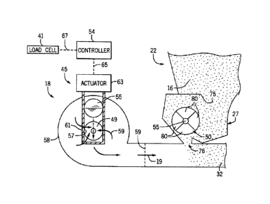
planting
material is deposited, each opener is followed by a packer wheel that packs
the
soil on top of the deposited material. Seeders commonly use pneumatic systems
to
transport planting material from a storage hopper to the soil to be deposited.
Typically, air flow is provided through tubes or distribution lines to
transport
product therethrough.
[0004] In certain configurations, an air cart is used to meter and
transport the
planting material (e.g., seeds, fertilizer, etc.) to ground engaging tools
within the
seeding implement. The air cart may include a hopper having one or more
compartments configured for holding various planting material. Certain air
carts
include a metering system configured to deliver metered quantities of material
into
1
{00786400.DOC /2 }
CA 02912897 2015-11-20
Docket No. 50193 (1016.373)
a tube or distribution line that transfers the material to the openers. The
metering
system will control distribution from the one or more compartments of the
hopper
to distribution lines such that each compartment provides planting material at
a
desired rate. Typically, an air cart includes a single large fan which
supplies air
flow to all distribution lines for pneumatic delivery of the planting material
therethrough. From the distribution lines, air flow is diverted into primary
distribution manifolds to secondary distribution manifolds that then feed the
distribution lines which deliver the planting material to individual opener
units.
[0005] Using a single fan to supply air to multiple distribution lines may
be
limiting with respect to controlling the distribution of various planting
material to
different opener units. More specifically, the use of a single fan to supply
air to
multiple distribution lines can result in uneven dispersal of air in the
distribution
lines. Further, in order to insure that the air pressure in the distribution
lines is
consistent, all the distribution lines are the same length, regardless of the
distance
between the air cart to the secondary distribution manifolds. As a result,
most
pneumatic systems require distribution lines of excess length, thereby adding
expense to the system and cluttering the equipment cluttered. As such, a more
accurate and reliable method of distributing air is needed.
[0006] Therefore, it is a primary object and feature of the present
invention to
provide an agricultural air cart assembly with individually controlled product
distribution lines.
[0007] It is a further object and feature of the invention to provide an
agricultural
air cart assembly with individually controlled product distribution lines
wherein
each distribution line is part of a self-contained unit.
[0008] It is a still further object and feature of the invention to provide
an
agricultural air cart assembly wherein the excess lines used on the air cart
is
minimized.
2
(00786400 DOC / 2 }
CA 02912897 2015-11-20
Docket No. 50193 (1016.373)
SUMMARY OF THE INVENTION
100091 In accordance with the present invention, an agricultural air cart
assembly
is provided for transmitting a controlled volume of product from a storage
compartment to a plurality of row units for depositing the product on an
agricultural field. The assembly includes a first distribution line for
receiving a
first supply of the product from the storage container therein. A rotatable
first fan
is operatively connected to the first distribution line. The first fan has an
intake
and is configured such that rotation of the first fan draws a volume of air
into the
fan through the intake and outputs an air flow having a pressure into the
first
distribution line which entrains and carries the first supply of the product
downstream toward a first row unit. A first fan shroud is movable between a
fully
opened position spaced from intake of the first fan and a closed position
wherein
first fan shroud overlaps the intake of the first fan and prevents the output
of the
air flow from the first fan.
100101 A second distribution line may be provided for receiving a second
supply of
the product from the storage container. A rotatable second fan is operatively
connected to the second distribution line. The second fan has an intake and is
configured such that rotation of the second fan draws a volume of air into the
second fan through the intake of the second fan and outputs an air flow having
a
pressure into the second distribution line which entrains and carries the
second
supply of the product downstream toward a second row unit. A second fan shroud
is movable between a fully opened position spaced from intake of the second
fan
and a closed position wherein second fan shroud overlaps the intake of the
second
fan and prevents the output of the air flow from the second fan. The first and
second fans are driven by a common drive mechanism.
3
{00786400 DOC / 2 )
CA 02912897 2015-11-20
Docket No. 50193 (1016.373)
[0011] A first meter wheel adapted for transferring the first supply of the
product
from the storage container to the first distribution line. The first meter
wheel is
adjustable to provide a desired rate at which the first supply of product is
transferred to the first distribution line. A second meter wheel is adapted
for
transferring the second supply of the product from the storage container to
the
second distribution line, the second meter wheel being adjustable to provide a
desired rate at which the second supply of product is transferred to the
second
distribution line. The first and second meter wheels may be independently
driven.
[0012] A controller may be operatively connected to the first fan shroud
for
positioning the fan shroud at a location between the fully opened position the
closed position. A first pressure sensor is operatively connected to the
controller
and is positioned to measure a pressure of the air flow in the first
distribution line.
The first pressure sensor provides a signal representative of the pressure of
the air
flow in the first distribution line to the controller.
[0013] In accordance with a further aspect of the present invention, an
agricultural
air cart apparatus is provided. The apparatus includes a storage container
holding
a product. First and second distribution lines are adapted for receiving
product
from the storage container and transporting the product to corresponding first
and
second row units. First and second product metering systems communicate with
the storage container. The first and second product metering systems
regulating
flows of product from the product hopper into the first and second
distribution
lines, respectively. A rotatable first fan is operatively connected to the
first
distribution line. The first fan has an intake and is configured such that
rotation of
the first fan draws a volume of air into the fan through the intake and
outputs an
air flow having a pressure into the first distribution line which entrains and
carries
the first supply of the product downstream toward a first row unit. A
rotatable
second fan is operatively connected to the second distribution line. The
second
fan has an intake and is configured such that rotation of the second fan draws
a
4
(00786400.DOC /2 )
CA 02912897 2015-11-20
Docket No. 50193 (1016.373)
volume of air into the second fan through the intake of the second fan and
outputs
an air flow having a pressure into the second distribution line which entrains
and
carries the second supply of the product downstream toward a second row unit.
A
controller is operable to adjust the pressures of the air flows outputted by
the first
and second fans.
[0014] The first and second product metering systems are operatively
connected to
the storage container and are configured to regulate the flows of product from
the
storage container into the first and second distribution lines. Each of the
first and
second product metering systems includes a meter wheel configured to rotate to
regulate a rate at which the product flows from the storage container into a
corresponding one of the first and second distribution lines to a desired
rate. A
first distribution manifold has an input coupled to the first distribution
line and an
output coupled to the first row unit. Likewise, a second distribution manifold
has
an input coupled to the second distribution line and an output coupled to the
second row unit. A first pressure sensor is operatively connected to the
controller
and is positioned within the first distribution manifold to measure a pressure
of the
air flow therein. The first pressure sensor provides a signal representative
of the
pressure of the air flow in the first distribution manifold to the controller.
A
second pressure sensor is operatively connected to the controller and is
positioned
with the second distribution manifold to measure a pressure of the air flow in
the
second distribution manifold. The second pressure sensor provides a signal
representative of the pressure of the air flow in the second distribution
manifold to
the controller. The controller adjusts the pressure of the air flow outputted
by the
first fan in response to the signal received from the first pressure sensor
and
adjusts the pressure of the air flow outputted by the second fan in response
to the
signal received from the second pressure sensor.
[0015] A first fan shroud is operatively connected to the controller and is
movable
between a fully opened position spaced from intake of the first fan and a
closed
{00786400.DOC / 2)
CA 02912897 2015-11-20
Docket No. 50193 (1016.373)
position wherein first fan shroud overlaps the intake of the first fan and
prevents
the output of the air flow from the first fan. A second fan shroud is
operatively
connected to the controller and is movable between a fully opened position
spaced
from intake of the second fan and a closed position wherein second fan shroud
overlaps the intake of the second fan and prevents the output of the air flow
from
the second fan. The controller is configured to position the first fan shroud
at a
location between the fully opened position the closed position to optimize the
pressure of the air flow in the first distribution line and to position the
second fan
shroud at a location between the fully opened position the closed position to
optimize the pressure of the air flow in the second distribution line.
100161 In accordance with a still further aspect of the present invention,
an
agricultural air cart apparatus including a product hopper for holding a
product and
first and second product metering systems communicating with the product
hopper
to regulate a flow of product from the product hopper is provided. The
apparatus
is characterized in that first and second distribution lines are adapted for
receiving
product from the product hopper and transporting the product to corresponding
first and second row units. The first and second product metering systems
regulate
flows of product from the product hopper into the first and second
distribution
lines, respectively. A rotatable first fan has an intake and output in
communication with the first distribution line. The first fan is configured to
draw
a volume of air into the first fan through the intake and output an air flow
having a
pressure into in the first distribution line which entrains and carries the
first supply
of the product downstream toward a first row unit. A rotatable second fan has
an
intake and output in communication with the second distribution line. The
second
fan is configured to draw a volume of air into the second fan through the
intake
and output an air flow having a pressure into the second distribution line
which
entrains and carries the second supply of the product downstream toward a
second
6
(00786400.DOC /2 )
CA 02912897 2015-11-20
Docket No. 50193 (1016.373)
row unit. The pressures of the air flowing in the first and second
distribution lines
are independently controlled.
[0017] A first fan shroud is operatively connected to the first fan and is
movable
between a fully opened position spaced from intake of the first fan and a
closed
position wherein first fan shroud overlaps the intake of the first fan and
prevents
the output of the air flow from the first fan. A second fan shroud is
operatively
connected to the second fan and is movable between a fully opened position
spaced from intake of the second fan and a closed position wherein second fan
shroud overlaps the intake of the second fan and prevents the output of the
air flow
from the second fan. A controller is operatively connected to the first and
second
fan shrouds for positioning the first and second fan shrouds at locations
between
the fully opened positions and the closed positions, the locations of the
first and
second fan shrouds setting the pressures of the air flowing in the first and
second
distribution lines. A first pressure sensor is operatively connected to the
controller
and is positioned to measure a pressure of the air flow in the first
distribution line.
The first pressure sensor provides a signal representative of the pressure of
the air
flow in the first distribution line to the controller. Asecond pressure sensor
is
operatively connected to the controller and is positioned to measure a
pressure of
the air flow in the second distribution line. The second pressure sensor
provides a
signal representative of the pressure of the air flow in the second
distribution line
to the controller. Each of the first and second product metering systems
includes a
meter wheel configured to rotate to dispense the product at a desired rate.
[0018] Other objects, features, and advantages of the invention will become
apparent to those skilled in the art from the following detailed description
and
accompanying drawings. It should be understood, however, that the detailed
description and specific examples, while indicating preferred embodiments of
the
present invention, are given by way of illustration and not of limitation.
Many
changes and modifications may be made within the scope of the present
invention
7
(00786400 DOC / 2)
CA 02912897 2015-11-20
Docket No. 50193 (1016.373)
without departing from the spirit thereof, and the invention includes all such
modifications.
BRIEF DESCRIPTION OF THE DRAWINGS
[0019] Preferred exemplary embodiments of the invention are illustrated in
the
accompanying drawings in which like reference numerals represent like parts
throughout.
[0020] FIG. 1 is an isometric view of a tractor pulling an implement
coupled to an
agricultural air cart assembly in accordance with the present invention;
[0021] FIG. 2 is a side view of the agricultural air cart assembly of the
present
invention coupled to the implement of FIG. 1;
[0022] FIG. 3 is a schematic diagram of the agricultural air cart assembly
of the
present invention coupled to an implement;
[0023] FIG. 4 is a schematic diagram of a fan assembly of the agricultural
air cart
assembly of the present invention for delivering airflow to dedicated
distribution
lines;
[0024] FIG. 5 is a schematic sectional representation of an individual
delivery unit
for the agricultural air cart assembly of the present invention depicting a
fan
shroud of the delivery unit in a fully opened position.
[0025] FIG. 6 is a schematic sectional representation, similar to FIG. 5,
of an
individual delivery unit for the agricultural air cart assembly of the present
invention depicting the fan shroud of the delivery unit in a closed position.
DETAILED DESCRIPTION OF THE DRAWINGS
[0026] Referring to FIG. 1, an agricultural particulate material delivery
system 5 is
shown that includes a tractor 8 and an agricultural air cart assembly 9. The
agricultural air cart assembly 9 includes, e.g. an air cart 10 such as a
PRECISION
AIR cart available from the Case IH company, and a material dispensing
8
{00786400.DOC / 2)
CA 02912897 2015-11-20
Docket No. 50193 (1016.373)
implement, e.g. a drill 12. As is conventional, the drill 12 includes a frame
34 to
which a set of row units 36 is coupled. By way of example, the row units 36
may
take the form of a plurality of disc-style opener units 36a, FIG. 1, or a
plurality of
tip-type opener units 36b, FIG. 2. The row units 36 are configured to cut a
furrow
into the soil and deposit the product 16 therein. Seed row finishing equipment
such
as wheel packers or closing wheels 42 may be arranged on the drill 12, such as
the
embodiment shown in FIG. 2 for closing the furrow(s).
100271 The air cart 10 and the drill 12 are hitched to the tractor 8 and/or
each other
in a conventional manner. The agricultural air cart assembly 9 further
includes a
pneumatic distribution system 14 operatively connected to the air cart 10 and
the
drill 12 for pneumatically delivering product 16 from the air cart 10 to the
drill 12
for pneumatic distribution of the product 16 to an agricultural field. By way
of
example, the product 16 is a particulate material that may be seed, such as
small
grains, and/or fertilizer, such as dry granular fertilizer.
100281 As hereinafter described, a controller 54, FIGS. 3-5, is configured
to adjust
the air flows in each of a plurality of distribution units 17 of pneumatic
distribution system 14, to thereby control distribution of the product 16 from
the
storage compartments 22 of the air cart 10 to the drill 12. It is contemplated
for an
operator to enter the configuration of the agricultural air cart assembly 9
into the
controller 54 and the desired operating parameters thereof. This configuration
may be entered manually, for example, from a pull-down menu presented to the
operator. Optionally, the agricultural air cart assembly 9 may include an
identifier
and the controller 54 may be configured to automatically detect the identifier
and
determine the agricultural air cart assembly 9 connected to the tractor 8. The
controller 54 may include an industrial computer or, e.g., a programmable
logic
controller (PLC), along with corresponding software and suitable memory for
storing such software and hardware, for controlling various components of the
agricultural air cart assembly 9, as hereinafter described. A database stored
in a
9
{00786400.DOC /2 }
- -
CA 02912897 2015-11-20
Docket No. 50193 (1016.373)
memory device may include additional configuration parameters such as the
number of storage compartments 22 present on the air cart 10, the number of
row
units 36 of the drill 12 and the like.
100291 Referring to FIGS. 1 and 2, the air cart 10 includes a frame 20 to
which
storage compartments 22 and wheels 24 are mounted. As hereinafter described,
the pneumatic distribution system 14 is configured to supply a controlled
volume
of product 16 from the storage compartments 22 to corresponding, individual
distribution lines 32, at desired delivery rates, so that the product 16 can
be
variably distributed to different portions of the drill 12 and different
locations on
the agricultural field. More specifically, the pneumatic distribution system
14 of
the agricultural air cart assembly 9 includes a plurality of distribution
units 17
arranged in a side-by-side relationship along the underside of air cart 10,
FIG. 4.
[0030] As seen in FIGS. 4-6, each of the distribution units 17 includes a
fan 18 for
generating an air flow generally designated by the reference numeral 19,
directed
through a corresponding distribution line 32. As hereinafter described, each
fan
18 includes a corresponding drive shaft 49 operatively connected to and driven
by
a common shaft 51 which, in turn, is operatively connected to a common drive
mechanism 52 by a belt, hydraulics or the like. The product 16 supplied by the
product metering unit 27 to the distribution line 32 becomes entrained in the
air
flow 19 through the distribution line 32 and carried by the air flow 19
downstream, as hereinafter described. Each of the distribution units 17 also
includes a product metering unit 27 having a meter wheel 50 for dispensing the
product 16 to the pneumatic distribution system 14 for delivery. The meter
wheel
50 of each distribution unit 17 is operatively connected to and driven by a
drive
mechanism (not shown) directly or via linkage such as a transmission, a drive
belt
or the like. Hence, the rotational speed of the meter wheel 50 may be varied
by
varying the speed of the motor or adjusting the linkage connecting the motor
thereto.
(00786400.DOC / 2)
CA 02912897 2015-11-20
Docket No. 50193 (1016.373)
100311 The meter wheel 50 of each product metering unit 27 is arranged between
the intake 75 and the exit 76 of the product metering unit 27 and may be
supported
by a rotatable shaft 55 extending concentrically through the meter wheel 50.
Each
meter wheel 50 has a drum-like configuration and includes multiple
compartments
80 circumferentially spaced about the outer periphery thereof. The
compartments
80 are sized to convey and control the volume and rate of product 16
transferred
from the storage compartment 22, through the exit 76 of product metering unit
27,
and into to distribution lines 32, for reasons hereinafter described.
100321 As heretofore described, each of the distribution units 17 also
includes a fan
18 associated with a corresponding distribution line 32. Each fan 18 is
support on
a corresponding drive shaft 49 which is operatively connected to common drive
shaft 51 by linkage 47, such as a drive belt or the like, FIG. 4. Each fan 18
provides the air flow 19 in distribution lines 32 so as entrain the product 16
supplied by the product metering unit 27 to the distribution line 32, as
heretofore
described. As is conventional, each fan 18 includes fan housing 58 housing a
plurality of circumferentially spaced blades or ribs which extend radially
from a
central hub. The central hub is operatively connected to and rotates with
drive
shaft 49 which extends into fan housing 58. Fan housing 58 further includes
intake 57, FIG. 5, axially aligned with drive shaft 49 and being adapted for
drawing air 59 in response to rotation of the fan blades of fan 18. As the
central
hub, and hence the fan blades, are rotated by drive shaft 49, air 59 is drawn
into
fan housing 58 through intake 57, turns 90 degrees and accelerates due to
centrifugal force as it flows over the fan blades and exits output 59 of fan
housing
58 as air flow 19. Output 59 of fan housing 58 of each fan 18 is in
communication
with a corresponding distribution line 32.
100331 It can be appreciated that by varying the dimensions of intake 57,
the
volume air drawn into intake 57 during rotation of the fan blades of a
corresponding fan 18 may be varied, thereby varying the volume, and hence the
11
{00786400 DOC / 2 )
CA 02912897 2015-11-20
Docket No. 50193 (1016.373)
pressure, of air flow 19 in distribution line 32. More specifically, it is
contemplated to operatively connect fan shroud assemblies 45 to fans 18. Fan
shroud assemblies 45 include fan shrouds 55 which are independently
controllable
and which selectively vary the dimensions of intakes 57 of fans 18 to control
the
pressures of the air flows 19 in distribution lines 32. Hence, by adjusting
the
volume of the air 59 drawn into fan housing 58 through intake 57, the pressure
of
the air flow 19 exiting output 59 of fan housing 58 is proportionally reduced.
100341 Each fan shroud assembly 45 includes fan shroud 55 defined by a
generally
circular plate 59 movable between a fully opened position, FIG. 5, wherein fan
shroud 55 is spaced from intake 57 of fan 18, and a closed position, FIG. 6,
wherein fan shroud 55 overlaps intake 57 and prevents air 59 from being drawn
into fan housing 58 through intake 57. It is contemplated for fan shroud 55 to
assume various positions between the fully opened position and the closed
position, such at fan shroud 55 partially obscures intake 57. In this manner,
the
position of fan shroud 55 may be used to control the volume of the air 59
drawn
into fan housing 58 through intake 57. As a result, by varying the position of
fan
shroud 55, air flow 19 exiting output 59 of fan housing 58 may range between
zero
(in other words, no air flow exiting output 59 of fan housing 58) and a
maximum
air flow that may be generated by fan 18 at its operating speed. Hence, as
described, the rotational speeds of the fans 18 do not need to be adjusted in
order
to change or optimize the volume of air entering the primary distribution
lines 32.
Rather, a single speed for all fans 18 may be implemented and the volumes of
air
entering the primary distribution lines 32 may be adjusted by simply adjusting
the
positions of corresponding fan shrouds 55.
100351 Fan shroud assemblies 45 further include guides 61 which guide movement
of fan shrouds 55 between the fully opened and closed positions. In addition,
actuators 63 are operatively connected to fan shrouds 55 to control movement
of
fan shrouds 55 between the fully opened and closed positions. Actuators 63, in
12
{00786400 DOC /2 }
CA 02912897 2015-11-20
Docket No. 50193 (1016.373)
turn, are operatively connected to controller 54 by lines 65. As hereinafter
described, controller 54 individually controls actuation of actuators 63 to
adjust
the position of fan shrouds 55, and hence, the pressures of the air flows 19
in
distribution lines 32. In other words, by varying the position of fan shroud
55, the
volume of the air flowing fan 18 and the pressure of the air flow 19 in a
corresponding distribution line 32 may be increased or decreased to an optimal
level.
[0036] As best seen in Fig. 3, each distribution line 32 is connected to
and in
communication with a corresponding secondary distribution manifold 38
supported on the frame 34 of the drill 12. It is intended for the product 16
entrained in the air flow 19 in distribution line 32 to be supplied to the
secondary
distribution manifold 38 under pressure. It is contemplated for each secondary
distribution manifold 38 to include a pressure sensor such as a load cell 41
provided therein for measuring the pressure of the air flow 19 received. For
reasons hereinafter described, the load cells 41 are operatively connected to
controller 54 by lines 67 for providing controller 54 with a signal
corresponding to
the pressure detected. Generally, the number of secondary distribution
manifolds
38 will match the number of distribution lines 32.
[0037] As is conventional, each secondary distribution manifold 38 has a
single
opening or input for receiving product 16 entrained in the air flow 19 in a
corresponding distribution line 32 and a plurality of outputs, each of which
is in
communication with a corresponding secondary distribution line 40. Each
secondary distribution manifolds 38 collects product 16 received at the input
thereof and causes product 16 to be distributed among secondary distribution
lines
40. While three secondary distribution lines 40 are depicted in FIG. 3 as
emanating from each secondary distribution manifold 38, any number of
secondary distribution lines 40 may be used without deviating from the scope
of
the present invention.
13
{00786400.DOC / 2 }
CA 02912897 2015-11-20
Docket No. 50193 (1016.373)
[0038] In operation, product 16 is loaded into the storage compartments 22
of the
air cart 10. The tractor 8 tows the agricultural air cart assembly 9 and the
drill 12
for pneumatic distribution of product 16 through the agricultural field.
Controller
54 causes actuator 63 to move fan shrouds 55 of fans 18 to a desired position,
e.g.
their fully opened positions, and fans 18 are activated such that the
pneumatic
distribution system 14 transfers product 16 using the distribution units 17 to
distribution lines 32. Product 16 flows through the distribution lines 32 to
secondary distribution manifolds 38 positioned on the drill 12 wherein the
secondary distribution manifolds 38 distributes product 16 through secondary
distribution lines 40 to the row units 36 for distribution into the furrows
formed
thereby.
[0039] It can be appreciated that as the tractor 8 is towed across the
agricultural
field, the rotational speed of the meter wheels 50 may be varied individually
or
collectively by a user or in accordance with the operating instructions of a
controller, e.g. controller 54, such that each meter wheel supplies a desired
amount
of product 16 to a corresponding distribution line 32. Each fan 18 of the
plurality
of distribution units 17 provides air flow 19 in distribution lines 32, as
heretofore
described, so as to entrain product 16 supplied to the distribution line 32
and carry
product 16 to the secondary distribution manifold 38 under pressure. Each
secondary distribution manifolds 38 collects product 16 received at the input
thereof and causes product 16 to be distributed among secondary distribution
lines
40 to corresponding row units 36, wherein product 16 is deposited in the
corresponding furrows cut thereby.
[0040] As previously described, the pressure of air flows 19 arriving at
the inputs
of the secondary distribution manifolds 38 is monitored by load cells 41 to
insure
that the proper volume of air is being delivered thereto. The pressure
measurements of load cells 41 of the secondary distribution manifolds 38 are
provided to controller 54 which determines if the air pressures in the
secondary
14
{00786400.DOC /2 }
CA 02912897 2015-11-20
Docket No. 50193 (1016.373)
distribution manifolds 38 are consistent and within acceptable levels. If the
air
pressures in the secondary distribution manifolds 38 are consistent and within
acceptable levels, the positions of the fan shrouds 55 of fans 18 are
maintained,
e.g., the fan shrouds 55 of fans 18 are maintained in their fully opened
positions.
[0041] If the air pressures in one or more of the secondary distribution
manifolds
38 are determined by controller 54 to be inconsistent with the other secondary
distribution manifolds 38 and/or outside of acceptable levels in response to
the
pressure measurements of load cells 41 of the secondary distribution manifolds
38,
controller 54 actuates actuators 63 of the fans 18 associated with the one or
more
of the secondary distribution manifolds 38 which have measured air pressures
inconsistent with the other secondary distribution manifolds 38 and/or outside
of
acceptable levels so as to adjust the positions of the corresponding fan
shrouds 55.
By adjusting the positions of the one or more fan shrouds 55, the volumes of
the
air flowing from fans 18 and the pressures of the air flows 19 in
corresponding
distribution lines 32 may be increased or decreased to an optimal level.
Thereafter, load cells 41 continue to measure the pressures of the air flows
19 in
secondary distribution manifolds and provide controller 54 with signals
corresponding to the pressures detected such that controller 54 may
continually
adjust the positions of the one or more fan shrouds 55 to maintain the
pressures of
the air flows 19 in corresponding distribution lines 32 at optimal levels.
[0042] The variable control of air flows 19 to the secondary distribution
manifolds
38 and of products 16 supplied to distribution lines 32 provides a number of
advantages. For example, the lengths of the primary distribution lines 32 may
be
adapted for the distance required to travel on the agricultural apparatus, and
do not
need to be uniform. In this manner, excess length of distribution lines 32 may
be
omitted. Another advantage is that it is easy to individually control the
amount of
air supplied to each distribution line 32 or product delivered to each
distribution
line 32, thus, adding flexibility to the machine's operation. In addition, by
(00786400.DOC / 2)
CA 02912897 2015-11-20
Docket No. 50193 (1016.373)
providing a plurality of self-contained distribution units 17 arranged in a
side-by-
side relationship along the underside of air cart 10, the agricultural air
cart
assembly 9 is easier to maintain and repair. Further, the air pressures in
distribution lines 32 may be individually controlled to adapt to different
types of
products 16 traveling therethrough.
100431 While fan shrouds 55 are shown to be used with multiple fans 18 which
are
driven by a common shaft 51 which, in turn, is operatively connected to a
common
drive mechanism 52 by a belt, hydraulics or the like, it is contemplated that
fan
shrouds 55 may be used in connection with independently driven fans 18. In
such
an arrangement, not only may fan shrouds 55 be used to maintain the pressures
of
the air flows 19 in corresponding distribution lines 32 at optimal levels, the
rotational speeds of the fans 18 may be individually adjusted to further tune
the
pressures of the air flows 19 in corresponding distribution lines 32 to
optimal
levels.
100441 Many changes and modifications could be made to the invention without
departing from the spirit thereof. The scope of these changes will become
apparent from the appended claims.
16
(00786400.DOC / 2)