Note: Descriptions are shown in the official language in which they were submitted.
CA 02913044 2015-11-25
LENGTH-ADJUSTABLE CONNECTOR FOR A DOWNHOLE TOOL
TECHNICAL FIELD
[0001] This relates to a downhole tool with a length-adjustable
connector, such as may be
used for a coring tool.
BACKGROUND
[0002] When drilling, a coring tool may be used to obtain a core sample
of the formation
being drilled. This generally involves a coring bit that is open in the
center, and a barrel
behind the coring bit. The barrel receives and holds the core sample as it
enters through the
center of the coring bit.
[0003] Often, the barrel and the related components will be made from a
different
material than the coring bit and the drill string that drives the coring bit.
As a result,
differences in the coefficient of thermal expansion between materials can
change the relative
position of the coring bit and the barrel when exposed to different
temperatures. While coring
tools are generally designed to account for this, the temperature in any
particular well may be
different from the design.
SUMMARY
[0004] According to an aspect, there is provided a length-adjustable
connector for a
downhole tool, comprising an outer tubular body having a first end, a second
end, an inner
surface that defines an inner bore, and a first locking profile accessible
from the inner bore, an
inner tubular body rotatably disposed within the inner bore of the outer
tubular body, the inner
tubular body comprising an outer surface and an inner surface, the inner
surface comprising a
second locking profile, a threaded connection between the inner surface of the
outer tubular
body and the outer surface of the inner tubular body, the threaded connection
causing axial
movement of the inner tubular body relative to the outer tubular body as the
inner tubular
body rotates relative to the outer tubular body, a locking sleeve having a
first end that is sized
to removably engage the first locking profile and a second end that is sized
to removably
engage the second locking profile, the locking sleeve preventing relative
rotation of the outer
tubular body and the inner tubular body when engaged with the first and second
locking
profiles, and a connector carried by the inner tubular body that extends
axially away from the
CA 02913044 2015-11-25
2
locking sleeve, the connector moving axially relative to the outer tubular
body as the inner
tubular body is rotated relative to the outer tubular body.
[0005] According to another aspect, the outer tubular body may comprise
threaded
connections for connecting to a downhole drill string.
[0006] According to another aspect, the locking sleeve receiver may
comprise one or
more axially-extending slots that engage one or more first locking keys that
extend outward
from the first end of the locking sleeve.
[0007] According to another aspect, the first locking profile may
comprise one more
axially-extending slots and the one or more first locking keys may
simultaneously engage the
axially-extending slots of each of the first locking profile and the locking
sleeve.
[0008] According to another aspect, the locking sleeve may comprise one or
more second
locking keys spaced that engage the second locking profile of the inner
tubular body.
[0009] According to another aspect, the second locking profile may
comprise an axially
extending slot in the inner surface of the inner tubular body.
[0010] According to another aspect, the inner tubular body may move
between a retracted
position and an extended position relative to the outer tubular body as the
inner tubular body
is rotated relative to the outer tubular body.
[0011] According to another aspect, the connector may be sized to be
received within the
inner bore of the outer tubular body in at least the retracted position.
[0012] In other aspects, the features described above may be combined
together in any
reasonable combination as will be recognized by those skilled in the art.
BRIEF DESCRIPTION OF THE DRAWINGS
CA 02913044 2015-11-25
3
[0013] These and other features will become more apparent from the
following
description in which reference is made to the appended drawings, the drawings
are for the
purpose of illustration only and are not intended to be in any way limiting,
wherein:
FIG. 1 is a side elevation cross-sectional view of a length-adjustable
connector for
a downhole tool in a retracted position.
FIG. 2 is a side elevation cross-sectional view of the length-adjustable
connector
for a downhole tool of FIG. 1 in an intermediate position.
FIG. 3 is a side elevation cross-sectional view of the length-adjustable
connector
for a downhole tool of FIG. 1 in an extended position.
FIG. 4 is a top plan cross-sectional view of the length adjustable connector
for a
downhole tool of FIG. 2 along the line A-A.
FIG. 5 is a top plan cross-sectional view of the length adjustable connector
for a
downhole tool of FIG. 2 along the line B-B.
FIG. 6 is a top plan cross-sectional view of the length adjustable connector
for a
downhole tool of FIG. 2 along the line C-C.
FIG. 7 is a side elevation cross-sectional view of an alternate embodiment of
a
length-adjustable connector for a downhole tool.
FIG. 8 is a side elevation cross-sectional view of a wrench for use with a
length-
adjustable connector for a downhole tool.
DETAILED DESCRIPTION
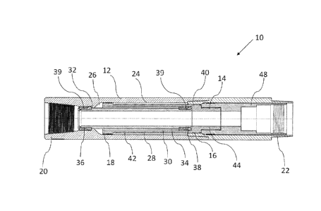
[0014] A length-adjustable connector for a downhole tool, generally
identified by
reference numeral 10, will now be described with reference to FIG. 1 through
6.
[0015] Referring to FIG. 1, length-adjustable connector 10 has an outer
tubular body 12,
an inner tubular body 14 that is positioned within outer tubular body 12 and
engages outer
tubular body 12 by a threaded connection 16. A locking sleeve 18 is used to
prevent relative
rotation of outer tubular body 12 and inner tubular body 14. The depicted
arrangement is
intended to allow inner tubular body 14 to be rotated relative to outer
tubular body 12 until a
desired position is achieved, and then locked into place by installing locking
sleeve 18.
CA 02913044 2015-11-25
4
[0016] In the depicted embodiment, outer tubular body 12 has a first end
20, a second end
22 and an inner surface 24 that defines an inner bore 26. In the depicted
embodiment, outer
tubular body 12 is designed as a sub and is threaded at either end such that
it can be installed
in a downhole string, such as a drill string. Inner tubular body 14 is
rotatably disposed within
inner bore 26 of outer tubular body 12 and has an outer surface 28 and an
inner surface 30.
There is a first locking profile 32 carried by outer tubular body 12 that is
accessible from
inner bore 26 and a second tubular locking profile 34 on inner surface 30 of
inner tubular
body 14. In the depicted embodiment, first and second locking profiles 32 and
34 are axially-
extending slots on the inner surface of outer tubular body 12 and inner
tubular body 14,
respectively. As can be seen, first locking profile 32 is shorter in length
than second locking
profile 34 as outer tubular body 12 is considered to be stationary, while
inner tubular body 14
is intended to move axially within outer tubular body 12, and a longer locking
profile allows
for a wider range of locations that can be used to secure inner tubular body
14.
[0017] As noted above, locking sleeve 18 is used to hold inner and outer
tubular bodies 12
and 14 in relative rotational positions. As depicted, locking sleeve 18 is a
tubular body with a
first end 36 that is sized and shaped to removably engage first locking
profile 32 and a second
end 38 that is sized and shaped to removably engage second locking profile 34.
When
engaged with first and second locking profiles 32 and 34, locking sleeve 18
prevents relative
rotation of outer tubular body 12 and inner tubular body 14. A shown, first
and second ends
36 and 38 of locking sleeve 18 are fitted with keys 39 that engage the slots
of first and second
locking profiles 32 and 34. As keys 39 have a constant thickness, they are
able to be slid
along locking profiles 32 and 34 until the desired position is received. Also,
as can be seen by
comparing FIG. 4, FIG. 5, and FIG. 6, which are cross-sections taken at
different positions
along the length of length-adjustable connector 10, some of the slots in
locking profile 32
extend the entire length of the shoulder in which they are formed, while
others do not. This
allows certain slots to act as a passageway for those keys 39 used to engage
locking profile 34
of inner tubular body 14 to pass through locking profile 32, while other slots
act as axial stops
to ensure inner tubular body 14 is inserted to the desired position. It will
be understood that
the same result could also be achieved in other ways, such as by making second
locking
profile 34 a smaller diameter than first locking profile. It will also be
understood that locking
CA 02913044 2015-11-25
sleeve 18 and locking profiles 32 and 34 may have different shapes or may be
manufactured
in different ways while still allowing locking sleeve 18 to engage both inner
and outer tubular
bodies 12 and 14 and secure them against relative rotation. In addition, it
will be understood
that the relative length of locking profiles may be changed as long as the
desired range of
5 locked positions are permitted.
[0018] Outer tubular body 12 and inner tubular body 14 are connected and
mounted
together by threaded connection 16. Threaded connection 16 has a first set of
threads 40 on
inner surface 24 of outer tubular body 12 and a second, matching set of
threads 42 on outer
surface 28 of inner tubular body 14. When locking profiles 32 and 34 are not
engaged, inner
tubular body 14 is able to rotate relative to outer tubular body 12, such that
threaded
connection 16 causes inner tubular body 14 to move axially relative to outer
tubular body 12
between a retracted and an extended position, as the case may be. By properly
setting inner
tubular body 14 within outer tubular body 12, length adjustable connector 10
may be set to
provide a desired effective length for a tool (not shown) that may be attached
to a connection
point 44. Inner tubular body 14 may be rotated by any suitable wrench that
engages inner
tubular body 14 from either end. An example of a suitable wrench 45 is shown
in FIG. 8,
which is provided with two sizes at either end, which allows it to be used for
different sizes of
length-adjustable connectors 10, depending on the size of tubing that is being
used. Wrench
45 is inserted such that it engages second locking profile 34 and then used to
rotate inner
tubular body 14. Once the desired length is achieved, wrench 45 is removed and
locking
sleeve 18 is inserted to engage both first and second profiles 32 and 34. In
the depicted
embodiment, care should be taken to ensure that first and second locking
profiles 32 and 34
are properly aligned to ensure locking sleeve 18 is properly inserted. Wrench
45 also has a
locking sleeve engagement end 47 that is sized to engage the inside surface of
locking sleeve
18 in order to allow locking sleeve 18 to be pulled out from within outer and
inner tubular
bodies 12 and 14.
[0019] Using the structure described above, length-adjustable connector
10 may be used
to adjust the position of a tool relative to outer tubular body 12, and thus
to the tubing string to
which outer tubular body 12 is attached. In particular, this is useful when
installing a tool that
CA 02913044 2015-11-25
6
is set within an outer tubing string, such as a core barrel for a coring tool.
Inner tubular body
14 is provided with connection point 44 that can be connected to a desired
tool. Connection
point 44 extends axially away, or downstream as depicted, from locking sleeve
18 locking
profile 34. As shown, outer tubular body 12 is formed from two parts, which
allows the
length to be changed by changing the second, or downstream, part in order to
properly
accommodate whatever is attached to connection point 44. As shown, in FIG. 1,
FIG. 2, and
FIG. 3, an attachment 48 is shown in the form of a tubular body that is
attached to connection
point 44 such that it retracts within outer tubular body 12 in the retracted
position, and extends
out from outer tubular body 12 in the extended position. Referring to FIG 7, a
different
attachment 48 is shown, which may allow for a float valve (not shown) that is
commonly used
in coring tools to be installed. Other attachments and other tools may be
attached to
attachment point 48 as will be recognized by those skilled in the art.
[0020] In this patent document, the word "comprising" is used in its non-
limiting sense to
mean that items following the word are included, but items not specifically
mentioned are not
excluded. A reference to an element by the indefinite article "a" does not
exclude the
possibility that more than one of the elements is present, unless the context
clearly requires
that there be one and only one of the elements.
[0021] The scope of the following claims should not be limited by the
preferred
embodiments set forth in the examples above and in the drawings, but should be
given the
broadest interpretation consistent with the description as a whole.