Note: Descriptions are shown in the official language in which they were submitted.
CA 2913188 2017-03-20
AIR-PRESSURE-TYPE DUAL-BIN AIR-POWERED SEPARATOR
TECHNICAL FIELD
[0001]The present invention relates to the technical art of pneumatic
separating system,
in particular to be applied in the tobacco manufacturing field, for use in the
separation
of the breakable materials.
BAC KGROUND
[0002] Principle of pneumatic separation: The pneumatic separation defines the
action
of floating and separating certain material in an air flow. By setting a
certain airflow
velocity, it makes the lighter part of the materials, with the lower
suspending speed than
the set speed, move upwards, the heavier parts move otherwise downwards, so
the
materials are essentially separated into two parts of the lighter and the
heavier. This
principle is widely applied in various industries, such as CN201454852 U
discloses a
device for separating heavier high-qualified seeds.
[0003] CN 2922496 Y discloses a device for pneumatic separating invalid
heavier stems
and debris from cutting tobacco, in which the lighter and effective cutting
tobacco is
carried away, then is separated with the gas-materiel separation equipment
after the
pipeline transportation. CN 102626257 A and CN 2791087 Y disclose a device for
use
in separating mixed material such as tobacco slice and stem. The effective
tobacco slice
being separated is transported by air, is separated thereof then by use of the
rotary
discharge equipment CN 101053868A discloses a device provided with binary
silos
for separating tobacco materials , wherein the different velocities are
adopted in two
silos result in twice separation of materials , the lighter and effective
materials are
carried away by air, then is separated with the gas-material separation
equipment after
the pipeline transmission.
[0004] It is indispensable for the lighter and effective materials to be
sorted by using
Page 1
CA 2913188 2017-03-20
the devices mentioned above, the gas-material separation equipment after the
pipeline
transportation. The moisture of material should be reduced, the mechanical
friction
become more intense in the processes of transport and separation. As a result,
it makes
material size becoming smaller, and leads to production of large amounts of
detritus,
reducing use value for the material. Additionally, the devices above can
simply
implement the singular function of sorting, as for managing gas-material
separation.
which is necessarily combined with other discharge equipment. In addition, the
correspondent equipment is complex and high energy consumption.
SUMMARY OF INVENTION
[0005]The purpose of the present invention is to solve the defects of the
prior art, to
provide a pneumatic separation apparatus with high efficiency, low energy
consumption,
simple structure, and low loss.
[0006]An apparatus for pneumatic separation disposed with binary silos
described in .
the present invention is achieved by the following technical solutions.
[0007] The shared upper side wall of the separation silo is communicated with
the
discharge silo thereof through a communication port, where an air curtain is
disposed
to isolate both silos from each other. The discharge port is disposed at the
bottom of the
discharge silo. A suction outlet is mounted on the top of the separation silo,
at the lower
part of the side wall thereof is disposed a feeding port, which is precisely
facing towards
the end of the belt conveyer. At the lower part of the separation silo is
arranged a
vibration trough, under which is disposed a damper plat, underside of which
has a air
inlet just located at the bottom of the separation silo. A rejection outlet is
installed
beneath at the end of the vibrating trough.
[0008] The mesh belt conveyer is horizontally arranged in the separation silo
and
the discharge silo, compromising an air curtain taking the structure with a
Page 2
CA 2913188 2017-03-20
communication port, where an auxiliary air inlet is provided, on the top of
which a
series of air holes disposed, which is vertically facing the mesh belt
conveyer.
[0009] The negative pressure at the suction outlet is 100-2100Pa smaller than
the
standard atmospheric pressure, the pressure at mesh on the vibrating trough is
100-
2000Pa larger than the standard atmospheric pressure, the air inlet connected
beneath
the damper plate takes a rectangular bending structure, the airflow direction
of the
horizontal section of which is consistent with the transferring direction of
the mesh belt
conveyer, and the pressure in the discharge silo is equal to the standard
atmospheric
pressure.
[0010] The discharge silo has a trumpet shape of which upper part is bigger
than lower
part, tilt sidewalls of which are provided with angle regulators, a damper
plate adopts
pull chute, which is mounted beneath the mesh vibrating trough.
[0011] The mesh belt conveyer is equipped with corrective and tensioning
devices.
[0012] At the end of the mesh belt conveyer, which is located in the discharge
silo, a
scratch brush is included.
[0013] By replacing the damper plate, which is located at the lower part of
the
separation silo, the positive pressure air flowing into the separation silo
can be adjusted,
and the air inlet is adopted with perpendicular angle bending structure, so
that the
pressure-balanced plane in the separation take forms with low pressure on the
right,
high on the left respectively.
[0014] The materials enter from the feed port to a separation silo on the belt
conveyor
or a vibrating trough in a way of horizontal throw, wherein the fine dust and
detritus,
whose size is less than dimension of the mesh hole on the belt conveyer, under
the effect
of negative pressure, infiltrate the mesh on belt conveyer and the suction
outlet into the
dust exhaust system; wherein the loose and lighter material, whose size is
bigger than
Page 3
CA 2913188 2017-03-20
the mesh hole on the belt conveyer, is attached to the belt conveyer under the
effect of
negative pressure; wherein the remaining materials, floats in the air and is
uplifted by
wind force of the positive pressure, wherein the lighter material gradually
are loosen
and separated from the heavier material in the process of falling by being
absorbed on
the belt conveyer after being lifted to the pressure equilibrium plane,
wherein the
surplus materials falling on the vibrating trough located at the bottom, which
are
transformed by thereof, and further loosen under the joint effect with the
forces of
vibrating transmission and the positive airflow from underside, wherein the
loose and
lighter material is absorbed on the belt conveyer by negative pressure, after
being lifted
to the pressure equilibrium plane. The material absorbed underside of the belt
conveyer
falls by gravity into the discharge outlet with the normal standard
atmospheric pressure
outside, wherein the heavier is transported by a vibrating trough to its slot
opening to
be removed.
[0015] An auxiliary air inlet located between the separation silo and
discharge silo, the
uniformly distributed vents blowing off positive airflow, which takes the
effect of
isolating the pressures from each other so that the air pressure inside the
discharge silo
the same as the standard atmospheric pressure outside, which also uplift the
materials
continually on the first stage when the materials are transferred into the
discharge silo,
so that the material fall collectively to the middle of the discharge port.
[0016] The material attached on the surface of mesh belt conveyer lost the
negative
pressure suction force and positive pressure lifting force from underside
after entering
into the discharge silo, separates itself with the mesh belt conveyer under
its own gravity,
and falls to the discharge outlet in a parabolic path, resulted by the inertia
of mesh belt
conveyer movement. A rotating brush mounted at the end of mesh belt conveyer,
which
is tangential to thereof, make relative motion reversely against the mesh belt
conveyer
driving. The rotating brush brings down all the materials attached to the mesh
belt
conveyer, to the discharge outlet.
Page 4
CA 2913188 2017-03-20
[0017] The present invention can achieve the material separation of different
flow by
adjusting the dimension of separation silo and the velocity of mesh belt
conveyer, can
separate the substance of different material by adjusting air pressure, wind
speed.
[0018] The beneficial effects of the present invention include, achieving for
multiple
sorting materials in a single device, thereby enhancing the separation
efficiency, so as
to increase the processing capacity of equipment in the unit of width
dimension, that
the unit of width dimension of device in the direction of feeding can process
larger flow
of materials, so that the apparatus of the present invention, compared to
other devices,
can minimize the size thereof in the condition of handling the same flow of
materials,
and lessen the amount of wind so as to achieve the effect of reducing energy
consumption.
[0019] The present invention avoids the particulate material from mechanical
friction
caused by the traditional separation equipment adopting the mechanism of air
material
separation and air lock discharge, eliminates size reduction and debris
produced by the
material crushing resulted by the mechanical friction, thereby improving the
utilization
of the material. The present invention is equally applicable to the technical
field of
pneumatic separating material, which the effective pa is heavier.
BRIEF DESCRIPTION OF DRAWINGS
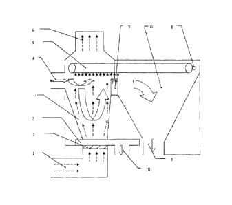
[0020] Fig.1 is a structure view of the present invention.
[0021] Legend: Air inlet 1; Damper plate 2; Mesh vibrating trough 3; Feeding
port 4;
Mesh belt conveyer 5; Suction outlet 6; Auxiliary air inlet 7; Scratch brush
8; Discharge
port 9; Rejection outlet 10; Separation silo 11; Discharge silo 12.
DETAILED DESCRIPTION OF THE INVENTION
[0022] Fig.1 is a construct view of a preferred embodiment of the present
invention,
Page 5
CA 2913188 2017-03-20
consisting of a air inlet 1, a damper plate 2, a mesh vibrating trough 3, a
feeding port 4,
a mesh belt conveyer5, a suction outlet 6, an auxiliary air inlet 7 a rotary
scratch brush
8, a discharge outlet 9, a rejection outlet 10 a separation silo 11, and a
discharge silo 12.
[00231 Operation process as shown, the material is transferred by vibrating
conveyor
from the feed port 4 (as fig.)into a separation silo 11(as fig.), due to the
inertia, makes
the parabolic movement forward, during the moving process, wherein the fine
dust and
detritus, whose size is less than dimension of the mesh hole on the belt
conveyer 5(as
fig.), infiltrate the mesh belt conveyer 5(as fig.) into the dust exhaust
system through
the suction outlet 6(as fig.); under the effect of negative pressure from the
suction outlet
6(as fig.), wherein a certain proportion of qualified material whose specific
weight is
light, is absorbed on the belt conveyer 5(as fig.); wherein the remaining
material,
uplifted by wind of the positive pressure from air inlet 1(as fig.), wherein
the lighter
material uplifted by positive pressure air is gradually separated from the
heavier , and
is absorbed on the belt conveyer 5 (as fig.) by passing through the pressure
equilibrium
plane of separation silo 11(as fig.), wherein the remaining material falls on
the vibrating
trough 3(as fig.), which are further loosen under the joint forces of
vibrating
transmission and the positive, so that wherein the lighter material is
separated from the
heavier once again, passes through the pressure equilibrium plane by uplifted
by
positive air, wherein the heavier material is transferred by the vibrating
trough 3 (as
fig.) and separated by falling to the rejection outlet 10, which is located on
the underside
thereof. The absorbed material on the belt conveyer 5 (as fig.) is taken into
the discharge
silo 12 (as fig.), due to the pressure in the discharge silo 12 (as fig.) same
with outside
atmospheric, therefore fall by gravity to the discharge port, the pneumatic
separation is
finally completed.
[0024] Preferred Embodiment: This embodiment is just in an example of
illustration on
tobacco pneumatic separation, which does not limit the scope of the present
invention.
After a resurgence of tobacco, feeding, storing leaves, heating
humidification, cutting,
Page 6
CA 2913188 2017-03-20
and drying, the cutting tobacco is transported into the separation silo 11 (as
fig.) of the
present invention as illustrated, due to the inertia, makes the parabolic
movement
downward, during the falling process, wherein the fine dust and tobacco
debris, whose
size is less than lmm (as the size of mesh hole on the belt conveyer 5 (as
fig.)), with
the effect of negative pressure, infiltrate the mesh belt conveyer 5 (as fig.)
into the dust
exhaust system through the suction outlet 6 (as fig.); under the effect of
negative
pressure above, wherein a certain proportion of qualified cutting tobacco
whose specific
weight is light, is absorbed on the belt conveyer 5 (as fig.); wherein the
remaining
material in the falling process, uplifted by wind of the positive pressure,
wherein the
lighter cutting tobacco is gradually separated from the heavier, passes
through the
pressure equilibrium plane of the separation silo 11 (as fig.) ,and is
absorbed on the belt
conveyer 5 (as fig.) by, wherein the remaining cutting tobacco and stems fall
on the
vibrating trough 3 (as fig.), the mixture is further loosen under the joint
forces of
vibrating trough 3 (as fig.)and the positive pressure air, so that wherein the
lighter cut
tobacco is separated from the heavier stems once again, passes through the
pressure
equilibrium plane by uplifted by positive pressure air, is absorbed by
negative pressure
on the belt conveyer 5 (as fig.); wherein the heavier stems are transferred by
the
vibrating trough 3 (as fig.) and separated by falling to the rejection outlet
10. The
absorbed cutting tobacco on the belt conveyer 5 (as fig.) is taken into the
discharge silo
12 (as fig.), due to the pressure in the discharge silo 12 (as fig.) same with
outside
atmospheric, fall by gravity to the discharge port 9 (as fig.), which is
transported by belt
conveyer into the next process. The technical tasks of sorting the stems out
of the cutting
tobacco are finally completed. Testing with the same batch of cutting tobacco
is
conducted to compare the subject invention with a traditional flexible air
sorting device,
the main technical indicators as the following:
Test Items Cut rag processed by Cut rag processed by Difference
a flexible air sorting the present invention
Page 7
CA 2913188 2017-03-20
device
Ratio of cut rag to 1.3 0.4 0.9
stem ( /0)
Ratio of long cutting 60.4 62.1 -1.7
tobacco (%)
Ratio of medium 25.3 24.7 0.6
size cutting tobacco
(%)
Ratio of short cutting 13.6 12.9 0.7
tobacco (%)
Ratio of detritus (c1/0) 0.7 0.3 0.4
Moisture reduction 0.6 0.2 0.4
(0/)
[0025] Test results indicate that the present invention has achieved the
multiple
separations of materials in a single device, has the advantages of low energy
consumption, high efficiency, less material crushed, and less moisture loss.
Page 8