Note: Descriptions are shown in the official language in which they were submitted.
CA 02913200 2015-11-20
WO 2015/012845
PCT/US2013/052087
EXPANDABLE BULLNOSE ASSEMBLY
FOR USE WITH A WELLBORE DEFLECTOR
BACKGROUND
[0001] The present disclosure relates generally to multilateral wellbores
and, more particularly, to an expandable bullnose assembly that works with a
wellbore deflector to allow entry into more than one lateral wellbore of a
multilateral wellbore.
[0002] Hydrocarbons can be produced through relatively complex.
wellbores traversing a subterranean formation. Some wellbores include one or
more lateral wellbores that extend at an angle from a parent or main wellbore.
Such wellbores are commonly called multilateral wellbores. Various devices and
downhole tools can be installed in a multilateral wellbore in order to direct
assemblies toward a particular lateral wellbore. A deflector, for example, is
a
device that can be positioned in the main wellbore at a junction and
configured
to direct a bullnose assembly conveyed downhole toward a lateral wellbore.
Depending on various parameters of the bullnose assembly, some deflectors also
allow the bullnose assembly to remain within the main wellbore and otherwise
bypass the junction without being directed into the lateral wellbore.
[0003] Accurately directing the bullnose assembly into the main
wellbore or the lateral wellbore can often be a difficult undertaking. For
instance, accurate selection between wellbores commonly requires that both the
deflector and the bullnose assembly be correctly oriented within the well and
otherwise requires assistance from known gravitational forces. Moreover,
conventional bullnose assemblies are typically only able to enter a lateral
wellbore at a junction where the design parameters of the deflector correspond
to the design parameters of the bullnose assembly. In order to enter another
lateral wellbore at a junction having a differently designed deflector, the
bullnose
assembly must be returned to the surface and replaced with a bullnose assembly
exhibiting design parameters corresponding to the differently designed
deflector.
This process can be time consuming and costly.
BRIEF DESCRIPTION OF THE DRAWINGS
[0004] The following figures are included to illustrate certain aspects of
the present disclosure, and should not be viewed as exclusive embodiments.
The subject matter disclosed is capable of considerable modifications,
1
CA 02913200 2015-11-20
-
_
WO 2015/012845
PCT/US2013/052087
alterations, combinations, and equivalents in form and function, without
departing from the scope of this disclosure.
[0005] FIG. 1 illustrates an exemplary well system that may employ
one or more principles of the present disclosure, according to one or more
embodiments.
[0006] FIGS. 2A-2C illustrate isometric, top, and end views,
respectively, of the deflector of FIG. 1, according to one or more
embodiments.
[0007] FIGS. 3A and 3B illustrate isometric and cross-sectional side
views, respectively, of an exemplary bullnose assembly, according to one or
more embodiments.
[0008] FIG. 4 illustrates the bullnose assembly of FIGS. 3A-3B in its
actuated configuration, according to one or more embodiments.
[0009] FIGS. 5A and 5B illustrate end and cross-sectional side views,
respectively, of the bullnose assembly of FIGS. 3A-3B in its default
configuration
as it interacts with the deflector of FIGS. 1-2, according to one or more
embodiments.
[0010] FIGS. 6A and 6B illustrate end and cross-sectional side views,
respectively, of the bullnose assembly of FIGS. 3A-3B in its actuated
configuration as it interacts with the deflector of FIGS. 1-2, according to
one or
more embodiments.
[0011] FIGS. 7A and 7B illustrate cross-sectional side views of another
exemplary bullnose assembly, according to one or more embodiments.
[0012] FIG. B illustrates an exemplary multilateral wellbore system that
may implement the principles of the present disclosure.
DETAILED DESCRIPTION
[0013] The present disclosure relates generally to multilateral wellbores
and, more particularly, to an expandable bullnose assembly that works with a
wellbore deflector to allow entry into more than one lateral wellbore of a
multilateral wellbore.
[0014] Disclosed is a bullnose assembly that is able to expand its
diameter while downhole such that it is able to be accurately deflected into
either a main wellbore or a lateral wellbore using a deflector. The deflector
has
a first channel that communicates to lower portions of the main wellbore, and
a
second channel that communicates with the lateral wellbore. If the diameter of
2
CA 02913200 2015-11-20
WO 2015/012845
PCT/US2013/052087
the bullnose assembly is smaller than the diameter of the first channel, the
bullnose assembly will be directed into the lower portions of the main
wellbore.
Alternatively, if the diameter of the bullnose assembly is larger than the
diameter of the first channel, the bullnose assembly will be directed into the
lateral wellbore. The variable nature of the disclosed bullnose assemblies
allows
for selective and repeat re-entry of any number of stacked multilateral wells
having multiple junctions that are each equipped with the deflector.
[0015] Referring to FIG. 1, illustrated is an exemplary well system 100
that may employ one or more principles of the present disclosure, according to
one or more embodiments. The well system 100 includes a main bore 102 and a
lateral bore 104 that extends from the main bore 102 at a junction 106 in the
well system 100. The main bore 102 may be a wellbore drilled from a surface
location (not shown), and the lateral bore 104 may be a lateral or deviated
wellbore drilled at an angle from the main bore 102. While the main bore 102
is
shown as being oriented vertically, the main bore 102 may be oriented
generally
horizontal or at any angle between vertical and horizontal, without departing
from the scope of the disclosure.
[0016] In some embodiments, the main bore 102 may be lined with a
casing string 108 or the like, as illustrated. The lateral bore 104 may also
be
lined with casing string 108. In other embodiments, however, the casing string
108 may be omitted from the lateral bore 104 such that the lateral bore 104
may be formed as an "open hole" section, without departing from the scope of
the disclosure.
[0017] In some embodiments, a tubular string 110 may be extended
within the main bore 102 and a deflector 112 may be arranged within or
otherwise form an integral part of the tubular string 110 at or near the
junction
106. The tubular string 110 may be a work string extended downhole within the
main bore 102 from the surface location and may define or otherwise provide a
window 114 therein such that downhole tools or the like may exit the tubular
string 110 into the lateral bore 104. In other embodiments, the tubular string
110 may be omitted and the deflector 112 may instead be arranged within the
casing string 108, without departing from the scope of the disclosure.
[0018] As discussed in greater detail below, the deflector 112 may be
used to direct or otherwise guide a bullnose assembly (not shown) either
further
downhole within the main bore 102, or into the lateral bore 104. To accomplish
3
CA 02913200 2015-11-20
WO 2015/012845
PCT/US2013/052087
this, the deflector 112 may include a first channel 116a and a second channel
116b. The first channel 116a may exhibit a predetermined width or diameter
118. Any bullnose assemblies that are smaller than the predetermined diameter
118 may be directed into the first channel 116a and subsequently to lower
portions of the main bore 102. In contrast, bullnose assemblies that are
greater
than the predetermined diameter 118 may slidingly engage a ramped surface
120 that forms an integral part or extension of the second channel 116b and
otherwise serves to guide or direct a bullnose assembly into the lateral bore
104.
[0019] Referring now to FIGS. 2A-2C, with continued reference to FIG.
1, illustrated are isometric, top, and end views, respectively of the
deflector 112
of FIG. 1, according to one or more embodiments. The deflector 112 may have
a body 202 that provides a first end 204a and a second end 204b. The first end
204a may be arranged on the uphole end (i.e., closer to the surface of the
wellbore) of the main bore 102 (FIG. 1) and the second end 204b may be
arranged on the downhole end (i.e., closer to the toe of the wellbore) of the
main bore 102. FIG. 2C, for example, is a view of the deflector 112 looking at
the first end 204a.
[0020] As illustrated, the deflector 112 may provide the first channel
116a and the second channel 116b, as generally described above. The deflector
112 may further provide or otherwise define the ramped surface 120 (not shown
in FIG. 2C) that generally extends from the first end 204a to the second
channel
116b and otherwise forms an integral part or portion thereof. As indicated,
the
first channel 116a extends through the ramped surface 120 and exhibits the
predetermined diameter 118 discussed above. Accordingly, any bullnose
assemblies (not shown) having a diameter that is smaller than the
predetermined diameter 118 may be guided through the ramped surface 120
and otherwise into the first channel 116a and subsequently to lower portions
of
the main bore 102. In contrast, bullnose assemblies having a diameter that is
greater than the predetermined diameter 118 will ride up the ramped surface
120 and into the second channel 116b which feeds the lateral bore 104.
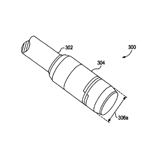
[0021] Referring now to FIGS. 3A and 3B, with continued reference to
FIGS. 1 and 2A-2C, illustrated are isometric and cross-sectional side views,
respectively, of an exemplary bullnose assembly 300, according to one or more
embodiments. The bullnose assembly 300 may constitute the distal end of a
tool string (not shown), such as a bottom hole assembly or the like, that is
4
- CA 02913200 2015-11-20
-
WO 2015/012845
PCT/US2013/052087
conveyed downhole within the main bore 102 (FIG. 1). In some embodiments,
the bullnose assembly 300 is conveyed downhole using coiled tubing (not
shown). In other embodiments, however, the bullnose assembly 300 may be
conveyed downhole using other types of conveyances such as, but not limited
to, drill pipe, production tubing, or any other conveyance capable of being
fluidly
pressurized. In yet other embodiments, the conveyance may be wireline,
slickline, or electrical line, without departing from the scope of the
disclosure.
The tool string may include various downhole tools and devices configured to
perform or otherwise undertake various wellbore operations once accurately
placed in the downhole environment. The bullnose assembly 300 may be
configured to accurately guide the tool string downhole such that it reaches
its
target destination, e.g., the lateral bore 104 of FIG. 1 or further downhole
within
the main bore 102.
[0022] To accomplish this, the bullnose assembly 300 may include a
body 302 and a bullnose tip 304 coupled or otherwise attached to the distal
end
of the body 302. In some embodiments, the bullnose tip 304 may form an
integral part of the body 302 as an integral extension thereof. As
illustrated, the
bullnose tip 304 may be rounded off at its end or otherwise angled or arcuate
such that it does not present sharp corners or angled edges that might catch
on
portions of the main bore 102 or the deflector 112 (FIG. 1) as it is extended
downhole.
[0023] The bullnose assembly 300 is shown in FIGS. 3A and 3B in a
default configuration where the bullnose tip 304 exhibits a first diameter
306a.
The first diameter 306a may be less than the predetermined diameter 118
(FIGS. 1 and 2A-2C) of the first channel 116a. Consequently, when the bullnose
assembly 300 is in the default configuration, it may be sized such that it is
able
to extend into the first channel 116a and into lower portions of the main bore
102. In contrast, as will be discussed in greater detail below, the bullnose
assembly 300 is shown in FIG. 4 in an actuated configuration where the
bullnose
tip 304 exhibits a second diameter 306b. The second diameter 306b is greater
than the first diameter 306a and also greater than the predetermined diameter
118 (FIGS. 1 and 2A-2C) of the first channel 116a. Consequently, when the
bullnose assembly 300 is in its actuated configuration, it may be sized such
that
it will be directed into the second channel 116b via the ramped surface 120
(FIGS. 2A-2C) and subsequently into the lateral bore 104.
5
CA 02913200 2015-11-20
WO 2015/012845
PCT/US2013/052087
[0024] In some embodiments, the bullnose assembly 300 may include a
piston 308 movably arranged within a piston chamber 310 defined within the
bullnose tip 304. The piston 308 may be operatively coupled to a wedge
member 312 disposed about the body 302 such that movement of the piston
308 correspondingly moves the wedge member 312. In the illustrated
embodiment, one or more coupling pins 314 (two shown) may operatively
couple the piston 308 to the wedge member 312. More particularly, the coupling
pins 314 may extend between the piston 308 and the wedge member 312
through corresponding longitudinal grooves 316 defined in the body 302.
[0025] In other embodiments, however, the piston 308 may be
operatively coupled to the wedge member 312 using any other device or
coupling method known to those skilled in the art. For example, in at least
one
embodiment, the piston 308 and the wedge member 312 may be operatively
coupled together using magnets (not shown). In such embodiments, one
magnet may be installed in one of the piston 308 and the wedge member 312,
and another corresponding magnet may be installed in the other of the piston
308 and the wedge member 312. The magnetic attraction between the two
magnets may be such that movement of one urges or otherwise causes
corresponding movement of the other.
[0026] The bullnose tip 304 may include a sleeve 318 and an end ring
319, where the sleeve 318 and the end ring 319 may form part of or otherwise
may be characterized as an integral part of the bullnose tip 304. Accordingly,
the bullnose tip 304, the sleeve 318, and the end ring 319 may cooperatively
define the "bullnose tip." As illustrated, the sleeve 318 generally interposes
the
end rig 319 and the bullnose tip 304. The wedge member 312 may be secured
about the body 302 between the sleeve 318 and the bullnose tip 304. More
particularly, the wedge member 312 may be movably arranged within a wedge
chamber 320 defined at least partially between the sleeve 318 and the bullnose
tip 304 and the outer surface of the body 302. In operation, the wedge member
312 may be configured to move axially within the wedge chamber 320.
[0027] The bullnose assembly 300 may further include a coil 322
wrapped about the bullnose tip 304. More particularly, the coil 322 may be
arranged within a gap 324 defined between the sleeve 318 and the bullnose tip
304 and otherwise sitting on or engaging a portion of the wedge member 312.
The coil 322 may be, for example, a helical coil or a helical spring that is
6
CA 02913200 2015-11-20
WO 2015/012845
PCT/US2013/052087
wrapped around the bullnose tip 304 one or more times. In other embodiments,
however, the coil 322 may be a series of snap rings or the like. In the
Illustrated
embodiment, two wraps or revolutions of the coil 322 are shown, but it will be
appreciated that more than two wraps (or a single wrap) may be employed,
without departing from the scope of the disclosure. In the default
configuration
(FIGS. 3A and 3B), the coil 322 sits generally flush with the outer surface of
the
bullnose tip 304 such that it also generally exhibits the first diameter 306a.
[0028] In some embodiments, the outer radial surface 326a of each
wrap of the coil 322 may be generally planar, as illustrated. The inner radial
surface 326b and the axial sides 326c of each wrap of the coil 322 may also be
generally planar, as also illustrated. As will be appreciated, the generally
planar
nature of the coil 322, and the close axial alignment of the sleeve 318 and
the
bullnose tip 304 with respect to the coil 322, may prove advantageous in
preventing the influx of sand or debris into the interior of the bullnose tip
304.
[0029] Referring now to FIG. 4, with continued reference to FIGS. 3A-
3B, illustrated is the bullnose assembly 300 in its actuated configuration,
according to one or more embodiments. In order to move the bullnose
assembly 300 from its default configuration (FIGS. 3A-3B) into its actuated
configuration (FIG. 4), the wedge member 312 may be actuated such that it
moves the coil 322 radially outward to the second diameter 306b. In some
embodiments, this may be accomplished by applying a hydraulic fluid 328 from a
surface location, through the conveyance (i.e., coiled tubing, drill pipe,
production tubing, etc.) coupled to the bullnose assembly 300, and from the
conveyance to the interior of the bullnose assembly 300 (i.e., the interior of
the
body 302). At the bullnose assembly 300, the hydraulic fluid 328 enters the
body 302 and acts on the piston 308 such that the piston 308 axially
translates
within the piston chamber 310 towards the distal end of the bullnose tip 304
(i.e., to the right in FIGS. 3B and 4). One or more sealing elements 330 (two
shown), such as 0-rings or the like, may be arranged between the piston 308
and the inner surface of the piston chamber 310 such that a sealed engagement
at that location results.
[0030] As the piston 308 translates axially within the piston chamber
310, it engages a biasing device 332 arranged within the piston chamber 310.
In some embodiments, the biasing device 332 may be a helical spring or the
like. In other embodiments, the biasing device 332 may be a series of
Belleville
7
CA 02913200 2015-11-20
WO 2015/012845
PCT/US2013/052087
washers, an air shock, or the like, without departing from the scope of the
disclosure. In some embodiments, the piston 308 may define a cavity 334 that
receives at least a portion of the biasing device 332 therein. Moreover, the
bullnose tip 304 may also define or otherwise provide a stem 336 that extends
axially from the distal end of the bullnose tip 304 in the uphole direction
(i.e., to
the left in FIGS. 3A and 3B). The stem 336 may also extend at least partially
into the cavity 334. The stem 336 may also be extended at least partially into
the biasing device 332 in order to maintain an axial alignment of the biasing
device 332 with respect to the cavity 334 during operation. As the piston 308
translates axially within the piston chamber 310, the biasing device 332 is
compressed and generates spring force.
[0031] Moreover, as the piston 308 translates axially within the piston
chamber 310, the wedge member 312 correspondingly moves axially since it is
operatively coupled thereto. In the illustrated embodiment, as the piston 308
moves, the coupling pins 314 translate axially within the corresponding
longitudinal grooves 316 and thereby move the wedge member 312 in the same
direction. As the wedge member 312 axially advances within the wedge
chamber 320, the wedge member 312 engages the coil 322 at a beveled surface
338 that forces the coil 322 radially outward to the second diameter 306b.
[0032] Once it is desired to return the bullnose assembly 300 to its
default configuration, the hydraulic pressure on the bullnose assembly 300 may
be released. Upon releasing the hydraulic pressure, the spring force built up
in
the biasing device 332 may force the piston 308 back to its default position,
thereby correspondingly moving the wedge member 312 and allowing the coil
322 to radially contract to the position shown in FIGS. 3A-3B. As a result,
the
bullnose tip 304 may be effectively returned to the first diameter 306a. As
will
be appreciated, such an embodiment allows a well operator to increase the
overall diameter of the bullnose tip 304 on demand while downhole simply by
applying pressure through the conveyance and to the bullnose assembly 300.
[0033] Those skilled in the art, however, will readily recognize that
several other methods may equally be used to actuate the wedge member 312,
and thereby move the bullnose assembly 300 between the default configuration
(FIGS. 3A-3B) and the actuated configuration (FIG. 4). For instance, although
not depicted herein, the present disclosure also contemplates using one or
more
actuating devices to physically adjust the axial position of the wedge member
8
CA 02913200 2015-11-20
WO 2015/012845
PCT/US2013/052087
312 and thereby move the coil 322 to the second diameter 306b. Such
actuating devices may include, but are not limited to, mechanical actuators,
electromechanical actuators, hydraulic actuators, pneumatic actuators,
combinations thereof, and the like. Such actuators may be powered by a
downhole power unit or the like, or otherwise powered from the surface via a
control line or an electrical line. The actuating device (not shown) may be
operatively coupled to the piston 308 or the wedge member 312 and otherwise
configured to move the wedge member 312 axially within the wedge chamber
320 and thereby force the coil 322 radially outward.
[0034] In yet other embodiments, the present disclosure further
contemplates actuating the wedge member 312 by using fluid flow around or
flowing past the bullnose assembly 300. In such embodiments, one or more
ports (not shown) may be defined through the bullnose tip 304 such that the
piston chamber 310 is placed in fluid communication with the fluids outside
the
bullnose assembly 300. A fluid restricting nozzle may be arranged in one or
more of the ports such that a pressure drop is created across the bullnose
assembly 300. Such a pressure drop may be configured to force the piston 308
toward the actuated configuration (FIG. 4) and correspondingly move the wedge
member 312 in the same direction. In yet other embodiments, hydrostatic
pressure may be applied across the bullnose assembly 300 to achieve the same
end.
[0035] While the bullnose assembly 300 described above depicts the
bullnose tip 304 as moving between the first and second diameters 306a,b,
where the first diameter is less than the predetermined diameter 118 and the
second diameter is greater than the predetermined diameter 118, the present
disclosure further contemplates embodiments where the dimensions of the first
and second diameters 306a,b are reversed. More particularly, the present
disclosure further contemplates embodiments where the bullnose tip 304 in the
default configuration may exhibit a diameter greater than the predetermined
diameter 118 and may exhibit a diameter less than the predetermined diameter
118 in the actuated configuration, without departing from the scope of the
disclosure. Accordingly, actuating the bullnose assembly 300 may entail a
reduction in the diameter of the bullnose tip 304, without departing from the
scope of the disclosure.
9
' CA 02913200 2015-11-20
_
WO 2015/012845 PC
T/1152013/052087
[0036] Referring now to FIGS. 5A and 5B, with continued reference to
FIGS. 1-4, illustrated are end and cross-sectional side views, respectively,
of the
bullnose assembly 300 in its default configuration as it interacts with the
deflector 112 of FIGS. 1 and 2, according to one or more embodiments. In its
default configuration, as discussed above, the bullnose tip 304 exhibits the
first
diameter 306a. The first diameter 306a may be less than the predetermined
diameter 118 (FIGS. 1 and 2A-2C) of the first channel 116a. Consequently, in
its default configuration the bullnose assembly 300 may be able to extend
through the ramped surface 120 and otherwise into the first channel 116a where
it will be guided into the lower portions of the main bore 102.
[0037] Referring now to FIGS. 6A and 6B, with continued reference to
FIGS. 1-4, illustrated are end and cross-sectional side views, respectively,
of the
bullnose assembly 300 in its actuated configuration as it interacts with the
deflector 112 of FIGS. 1 and 2, according to one or more embodiments. In the
actuated configuration, the coil 322 has been forced radially outward and
thereby effectively increases the diameter of the bullnose tip 304 from the
first
diameter 306a (FIGS. 5A-5B) to the second diameter 306b. The second
diameter 306b is greater than the predetermined diameter 118 (FIGS. 1 and 2A-
2C) of the first channel 116a. Consequently, upon encountering the deflector
112 in the actuated configuration, the bullnose assembly 300 is prevented from
entering the first channel 116a, but instead slidingly engages the ramped
surface 120 which serves to deflect the bullnose assembly 300 into the second
channel 116b and subsequently into the lateral bore 104 (FIG. 1).
[0038] Referring now to FIGS. 7A and 7B, illustrated are cross-sectional
side views of another exemplary bullnose assembly 700, according to one or
more embodiments. The bullnose assembly 700 may be similar in some
respects to the bullnose assembly 300 of FIGS. 3A and 3B and therefore may be
best understood with reference thereto, where like numeral will represent like
elements not described again in detail. Similar to the bullnose assembly 300,
the bullnose assembly 700 may be configured to accurately guide a tool string
or
the like downhole such that it reaches its target destination, e.g., the
lateral
bore 104 of FIG. 1 or further downhole within the main bore 102. Moreover,
similar to the bullnose assembly 300, the bullnose assembly 700 may be able to
alter its diameter such that it is able to interact with the deflector 112 and
CA 02913200 2015-11-20
WO 2015/012845
PCT/US2013/052087
thereby selectively determine which path to follow (e.g., the main bore 102 or
the lateral bore 104).
[0039] More particularly, the bullnose assembly 700 is shown in FIG. 7A
in its default configuration where the bullnose tip 304 exhibits a first
diameter
702a. The first diameter 702a may be less than the predetermined diameter
118 (FIGS. 1 and 2A-2C) of the first channel 116a. Consequently, when the
bullnose assembly 700 is in the default configuration, it may be sized such
that it
is able to extend through the ramped surface 120 (FIGS. 2A-2C) and otherwise
into the first channel 116a where it will be guided Into the lower portions of
the
main bore 102.
[0040] In contrast, the bullnose assembly 700 is shown in FIG. 7B in its
actuated configuration where the bullnose tip 304 exhibits a second diameter
702b. The second diameter 702b is greater than the first diameter 702a and
also greater than the predetermined diameter 118 (FIGS. 1 and 2A-2C) of the
first channel 116a. Consequently, upon encountering the deflector 112 in the
actuated configuration, the bullnose assembly 700 is prevented from entering
the first channel 116a, but instead slidingly engages the ramped surface 120
(FIGS. 2A-2C) which deflects the bullnose assembly 700 into the second channel
116b and subsequently into the lateral bore 104 (FIG. 1).
[0041] In order to move between the default and actuated
configurations, the bullnose assembly 700 may include a piston 704 arranged
within a piston chamber 706. The piston chamber 706 may be defined within a
collet body 708 coupled to or otherwise forming an integral part of the
bullnose
tip 304. The collet body 708 may define a plurality of axially extending
fingers
710 (best seen in FIG. 7B) that are able to flex upon being forced radially
outward. The collet body 708 further includes a radial protrusion 712 defined
on
the inner surface of the collet body 708 and otherwise extending radially
inward
from each of the axially extending fingers 710. The radial protrusion 712 may
be configured to interact with a wedge member 713 defined on the outer surface
of the piston 704.
[0042] The piston 704 may include a piston rod 714. The piston rod
714 may be actuated axially in order to correspondingly move the piston 704
within the piston chamber 706 such that the wedge member 713 is able to
interact with the radial protrusion 712. In some embodiments, similar to the
piston 308 of FIG. 3B, the piston rod 714 may be actuated by hydraulic
pressure
11
= CA 02913200 2015-11-20
WO 2015/012845
PCT/US2013/052087
acting on an end (not shown) of the piston rod 714. In other embodiments,
however, piston rod 714 may be actuated using one or more actuating devices
to physically adjust the axial position of the piston 704. The actuating
device
(not shown) may be operatively coupled to the piston rod 714 and configured to
move the piston 704 back and forth within the piston chamber 706. In yet other
embodiments, the present disclosure further contemplates actuating the piston
rod 714 using fluid flow around the bullnose assembly 700 or hydrostatic
pressure, as generally described above.
[0043] As the piston 704 moves axially within the piston chamber 706,
it compresses a biasing device 716 arranged within the piston chamber 706.
Similar to the biasing device 332 of FIGS. 3A and 4, the biasing device 716
may
be a helical spring, a series of Belleville washers, an air shock, or the
like. In
some embodiments, the piston 308 defines a cavity 718 that receives the
biasing device 716 at least partially therein. The opposing end of the biasing
device 716 may engage the inner end 720 of the bullnose tip 304. Compressing
the biasing device 716 with the piston 704 generates a spring force.
[0044] Moreover, as the piston 704 moves axially within the piston
chamber 706, the wedge member 713 engages the radial protrusion 712 and
forces the axially extending fingers 710 radially outward. This is seen in
FIG.
7B. Once forced radially outward, the bullnose tip 304 effectively exhibits
the
second diameter 702b, as described above. To
return to the default
configuration, the process is reversed and the bullnose tip 304 is returned to
the
first diameter 702a.
[0045] Referring again to FIGS. 5A-5B and 6A-6B, with continued
reference to FIGS. 7A and 7B, it will be appreciated that the bullnose
assembly
300 may be replaced with the bullnose assembly 700 described in FIGS. 7A and
7B, without departing from the scope of the disclosure. For instance, in its
default configuration, the bullnose tip 304 of the bullnose assembly exhibits
the
first diameter 702a and therefore is able to extend through the ramped surface
120 and otherwise into the first channel 116a where it will be guided into the
lower portions of the main bore 102. Moreover, in the actuated configuration,
the diameter of the bullnose assembly 700 is increased to the second diameter
702b, and therefore, upon encountering the deflector 112 in the actuated
configuration, the bullnose assembly 700 is prevented from entering the first
channel 116a. Rather, the bullnose tip 304 slidingly engages the ramped
12
- CA 02913200 2015-11-20
_
WO 2015/012845
PCT/US2013/052087
surface 120 which deflects the bullnose assembly 700 into the second channel
116b and subsequently into the lateral bore 104 (FIG. 1).
[0046] Accordingly, which bore (e.g., the main bore 102 or the lateral
bore 104) a bullnose assembly 300, 700 enters is primarily determined by the
relationship between the diameter of the bullnose tip 304 and the
predetermined
diameter 118 of the first channel 116a. As a result, it becomes possible to
"stack" multiple junctions 106 (FIG. 1) having the same deflector 112 design
in
a single multilateral well and entering respective lateral bores 104 at each
junction 106 with a single, expandable bullnose assembly 300, 700, all In a
single trip into the well.
[0047] Referring to FIG. 8, with continued reference to the previous
figures, illustrated is an exemplary multilateral wellbore system 800 that may
implement the principles of the present disclosure. The wellbore system 800
may include a main bore 102 that extends from a surface location (not shown)
and passes through at least two junctions 106 (shown as a first junction 106a
and a second junction 106b). While two junctions 106a,b are shown in the
wellbore system 800, it will be appreciated that more than two junctions
106a,b
may be utilized, without departing from the scope of the disclosure.
[0048] At each junction 106a,b, a lateral bore 104 (shown as first and
second lateral bores 104a and 104b, respectively) extends from the main bore
102. The deflector 112 of FIGS. 2A-2C may be arranged at each junction
106a,b. Accordingly, each junction 106a,b includes a deflector 112 having a
first
channel 116a that exhibits a first diameter 118 and a second channel 116b.
[0049] In exemplary operation, an expandable bullnose assembly, such
as the bullnose assemblies 300, 700 described herein, may be introduced
downhole and actuated in order to enter the first and second lateral bores
104a,b at each junction 106a,b, respectively. For instance, if it is desired
to
enter the first lateral bore 104a, the bullnose assembly 300, 700 may be
actuated prior to reaching the deflector 112 at the first junction 106a. As a
result, the bullnose assembly 300, 700 will exhibit the second diameter 306b,
702b and thereby be directed into the second channel 116b since the second
diameter 306b, 702b is greater than the predetermined diameter 118 of the
first
channel 116a. Otherwise, the bullnose assembly 300, 700 may remain in its
default configuration with the first diameter 306a, 702a and pass through the
first channel 116a of the deflector 112 at the first junction 106a.
13
CA 02913200 2015-11-20
WO 2015/012845
PCT/US2013/052087
[0050] Once past the first junction 106a, the bullnose assembly 300,
700 may enter the second lateral bore 104b by being actuated prior to reaching
the deflector 112 at the second junction 106b. As a result, the bullnose
assembly 300, 700 will again exhibit the second diameter 306b, 702b and
thereby be directed into the second channel 116b at the deflector 112 of the
second junction 106b since the second diameter 306b, 702b is greater than the
predetermined diameter 118 of the first channel 116a. If it is desired to pass
through the deflector 112 of the second junction 106b and into the lower
portions of the main bore 102, the bullnose assembly 300, 700 may remain in
its
default configuration with the first diameter 306a, 702a and pass through the
first channel 116a of the deflector 112 at the second junction 106b.
[0051] Embodiments disclosed herein include:
[0052] A. A well system that includes a deflector arranged within a
main bore of a wellbore and defining a first channel that exhibits a
predetermined diameter and communicates with a lower portion of the main
bore, and a second channel that communicates with a lateral bore, and a
bullnose assembly including a body and a bullnose tip arranged at a distal end
of
the body, the bullnose tip being actuatable between a default configuration,
where the bullnose tip exhibits a first diameter, and an actuated
configuration,
where the bullnose tip exhibits a second diameter different than the first
diameter, wherein the deflector is configured to direct the bullnose assembly
into
one of the lateral bore and the lower portion of the main bore based on a
diameter of the bullnose tip as compared to the predetermined diameter.
[0053] B. A bullnose assembly that includes a body, and a bullnose tip
arranged at a distal end of the body, the bullnose tip being configured to
move
between a default configuration, where the bullnose tip exhibits a first
diameter,
and an actuated configuration, where the bullnose tip exhibits a second
diameter
that is different than the first diameter.
[0054] C. A multilateral wellbore system that includes a main bore
having a first junction and a second junction spaced downhole from the first
junction, a first deflector arranged at the first junction and defining a
first
channel that exhibits a predetermined diameter and communicates with a first
lower portion of the main bore, and a second channel that communicates with a
first lateral bore, a second deflector arranged at the second junction and
defining
a third channel that exhibits the predetermined diameter and communicates with
14
CA 02913200 2015-11-20
WO 2015/012845
PCT/US2013/052087
a second lower portion of the main bore, and a fourth channel that
communicates with a second lateral bore, and a bullnose assembly Including a
body and a bullnose tip arranged at a distal end of the body, the bullnose
assembly being configured to move between a default configuration, where the
bullnose tip exhibits a first diameter, and an actuated configuration, where
the
bullnose tip exhibits a second diameter that is different than the
predetermined
diameter, wherein the first and second deflectors are configured to direct the
bullnose assembly into one of the first and second lateral bores and the first
and
second lower portions of the main bore based on a diameter of the bullnose tip
as compared to the predetermined diameter.
[0055] Each of embodiments A, B, and C may have one or more of the
following additional elements in any combination: Element 1: wherein the
deflector further includes a ramped surface that guides the bullnose assembly
to
the second channel when the diameter of the bullnose tip is greater than the
predetermined diameter. Element 2: wherein the first diameter is less than the
predetermined diameter and the second diameter is greater than both the first
diameter and the predetermined diameter, and wherein, when the bullnose tip
exhibits the first diameter, the bullnose assembly is directed into the first
channel and the lower portion of the main bore, and wherein, when the bullnose
tip exhibits the second diameter, the bullnose assembly is directed into the
second channel and the lateral bore. Element 3: wherein the bullnose assembly
further includes a piston movably arranged within a piston chamber defined
within the bullnose tip, a wedge member operatively coupled to the piston such
that movement of the piston correspondingly moves the wedge member, and a
coil arranged about the bullnose tip and in contact with the wedge member, the
piston being actuatable such that the wedge member is moved to radially
expand the coil, wherein, when the coil is radially expanded, the diameter of
the
bullnose tip exceeds the predetermined diameter. Element 4: wherein the
piston is actuatable using at least one of hydraulic pressure acting on the
piston,
an actuating device operatively coupled to the piston, and a pressure drop
created across the bullnose assembly that forces the piston to move within the
piston chamber. Element 5: wherein the bullnose assembly further includes a
collet body forming at least part of the bullnose tip and defining a plurality
of
axially extending fingers, a radial protrusion defined on an inner surface of
the
collet body and extending radially inward from each axially extending finger,
and
' CA 02913200 2015-11-20
WO 2015/012845
PCT/US2013/052087
a piston movably arranged within a piston chamber defined within the collet
body and having a wedge member defined on an outer surface thereof, the
piston being actuatable such that the wedge member engages the radial
protrusion and forces the plurality of axially extending fingers radially
outward,
wherein, when the plurality of axially extending fingers is forced radially
outward, the diameter of the bullnose tip exceeds the predetermined diameter.
Element 6: wherein the piston is actuatable using at least one of hydraulic
pressure acting on the piston, an actuating device operatively coupled to the
piston, and a pressure drop created across the bullnose assembly that forces
the
piston to move within the piston chamber. Element 7: wherein the first
diameter is greater than the predetermined diameter and the second diameter is
less than both the first diameter and the predetermined diameter, and wherein,
when the bullnose tip exhibits the first diameter, the bullnose assembly is
directed into the second channel and the lateral bore, and wherein, when the
bullnose tip exhibits the second diameter, the bullnose assembly is directed
into
the first channel and the lower portion of the main bore.
[0056] Element 8: wherein the first diameter is less than the
predetermined diameter and the second diameter is greater than both the first
diameter and the predetermined diameter, and wherein when the bullnose
assembly is in the default configuration it is able to be directed into the
first and
third channels and the first and second lower portions of the main bore,
respectively, and wherein, when the bullnose assembly is in the actuated
configuration it is able to be directed into the second and fourth channels
and
the first and second lateral bores, respectively. Element 9: wherein the first
diameter is greater than the predetermined diameter and the second diameter is
less than both the first diameter and the predetermined diameter, and wherein
when the bullnose assembly is in the default configuration it is able to be
directed into the second and fourth channels and the first and second lateral
bores, respectively, and wherein, when the bullnose assembly is in the
actuated
configuration it is able to be directed into the first and third channels and
the
first and second lower portions of the main bore. Element 10: wherein the
first
and second deflectors each include a ramped surface that guides the bullnose
assembly to the second and fourth channels, respectively, when the bullnose
assembly is in the actuated configuration.
16
CA 2913200 2017-04-12
[0057] Therefore, the disclosed systems and methods are well adapted
to attain the ends and advantages mentioned as well as those that are inherent
therein. The particular embodiments disclosed above are illustrative only, as
the
teachings of the present disclosure may be modified and practiced in different
but equivalent manners apparent to those skilled in the art having the benefit
of
the teachings herein. Furthermore, no limitations are intended to the details
of
construction or design herein shown, other than as described in the claims
below. It is
therefore evident that the particular illustrative embodiments
disclosed above may be altered, combined, or modified and all such variations
are considered within the scope of the present disclosure. The systems and
methods illustratively disclosed herein may suitably be practiced in the
absence
of any element that is not specifically disclosed herein and/or any optional
element disclosed herein. While compositions and methods are described in
terms of "comprising," "containing," or "including" various components or
steps,
the compositions and methods can also "consist essentially of" or "consist of"
the
various components and steps. All numbers and ranges disclosed above may
vary by some amount. Whenever a numerical range with a lower limit and an
upper limit is disclosed, any number and any included range falling within the
range is specifically disclosed. In particular, every range of values (of the
form,
"from about a to about b," or, equivalently, "from approximately a to b," or,
equivalently, "from approximately a-b") disclosed herein is to be understood
to
set forth every number and range encompassed within the broader range of
values. Also, the terms in the claims have their plain, ordinary meaning
unless
otherwise explicitly and clearly defined by the patentee. Moreover, the
indefinite
articles "a" or "an," as used in the claims, are defined herein to mean one or
more than one of the element that it introduces. If there is any conflict in
the
usages of a word or term in this specification and one or more patent or other
documents that may be referred to herein, the definitions that are consistent
with this specification should be adopted.
17