Note: Descriptions are shown in the official language in which they were submitted.
1
Mixing of recycle gas with fuel gas to a burner
The present invention is directed to combustion of
hydrocarbon fuel and in particular to a burner with a
recycle gas duct for use in hydrocarbon fuelled combustion
reactors.
Burners of a combustion reactant are mainly used for firing
gas-fuelled industrial furnaces and process heaters, which
require a stable flame with high combustion intensities.
Conventionally designed burners include a burner tube with
a central tube for fuel supply surrounded by an oxidiser
supply port. Intensive mixing of fuel and oxidiser in a
combustion zone is achieved by passing the oxidiser through
a swirler installed at the burner face on the central tube.
The stream of oxidiser is, thereby, given a swirling-flow,
which provides a high degree of internal and external
recirculation of combustion products and a high combustion
intensity.
Recycle gas from a Fisher Tropsh synthesis may cause severe
metal dusting when mixed with hot feed gas to a syngas
preparation unit, for example to the natural gas feed to an
autohermal reformer. Therefore known art mixing
arrangements are of complicated mechanical design, using
expensive non reliable materials and coatings and/or
installation of expensive recycle gas conversion reactor
systems.
In one aspect, the present invention provides a burner
comprising means to mix a recycle gas just prior to and in
the combustion zone of a catalytic reactor, thus avoiding
CA 2913213 2019-07-23
2
all metal dusting issues related to the above described
mixing problems.
US 2008035890 discloses a process to prepare a synthesis
gas comprising hydrogen and carbon monoxide comprises
performing a partial oxidation on a methane comprising feed
using a multi-orifice burner provided with an arrangement
of separate passages, wherein the gaseous hydrocarbon
having an elevated temperature flows through a passage of
the burner, an oxidizer gas flows through a separate
passage of the burner and wherein the passage for gaseous
hydrocarbon feed and the passage for oxidizer gas are
separated by a passage through which a secondary gas flows,
wherein the secondary gas comprises hydrogen, carbon
monoxide and/or a hydrocarbon.
A swirling burner for use in small and medium scale
applications with substantially reduced internal
recirculation of combustion products toward the burner face
is disclosed in US patent No. 5,496,170. The burner design
disclosed in this patent results in a stable flame with
high combustion intensity and without detrimental internal
recirculation of hot combustion products by providing the
burner with a swirling-flow of oxidiser having an overall
flow direction concentrated along the axis of the
combustion zone and at the same time directing the fuel gas
flow towards the same axis. The disclosed swirling-flow
burner comprises a burner tube and a central oxidiser
supply tube concentric with and spaced from the burner
tube, thereby defining an annular fuel gas channel between
the tubes, the oxidiser supply tube and the fuel gas
channel having separate inlet ends and separate outlet
ends. U-shaped oxidiser and fuel gas injectors are arranged
CA 2913213 2019-07-23
3
coaxial at the burner face. The burner is further equipped
with a bluff body with static swirler blades extending
inside the oxidiser injector. The swirler blades are
mounted on the bluff body between their upstream end and
their downstream end and extend to the surface of the
oxidiser injection chamber.
US2002086257 describes a swirling-flow burner with a burner
tube comprising a central oxidiser supply tube and an outer
concentric fuel supply tube, the oxidiser supply tube being
provided with a concentric cylindrical guide body having
static swirler blades and a central concentric cylindrical
bore, the swirler blades extending from outer surface of
the guide body to inner surface of oxidiser supply tube
being concentrically arranged within space between the
guide body and inner wall at lower portion of the oxidiser
supply tube.
US2007010590 A process for the production of hydrocarbons
is described including; a) subjecting a mixture of a
hydrocarbon feedstock and steam to catalytic steam
reforming to form a partially reformed gas, b) subjecting
the partially reformed gas to partial combustion with an
oxygen-containing gas and bringing the resultant partially
combusted gas towards equilibrium over a steam reforming
catalyst to form a reformed gas mixture, c) cooling the
refolmed gas mixture to below the dew point of the steam
therein to condense water and separating condensed water to
give a de-watered synthesis gas, d) synthesising
hydrocarbons from side de-watered synthesis gas by the
Fischer-Tropsch reaction and e) separating the hydrocarbons
from co-produced water, characterised in that at least part
of said co-produced water is fed to a saturator wherein it
CA 2913213 2019-07-23
4
is contacted with hydrocarbon feedstock to provide at least
part of the mixture of hydrocarbon feedstock and steam
subjected to steam reforming
Despite the state of the art as described in the above
references, there is a need for a better solution to the
problem of mixing an aggressive recycle gas in hydrocarbon
fuelled combustion reactors.
Accordingly, in one aspect this invention provides a burner
where a recycle process gas is flowing in between an inner
and an outer tube of the burner, with a velocity that keeps
the metal temperature below a critical metal dusting
temperature. Existing recycle process gas lances have
proven to be basically free of metal dusting due to low
metal temperature and thus the recycle process gas nozzle
of the present invention have the same advantage.
Outlet velocity of the recycle process gas nozzle should be
the same as the fuel gas velocity at the position of the
recycle gas nozzle tip. The position of the recycle gas
nozzle tip is chosen in such a way that the oxidant and
fuel gas part of the burner will only be in contact with
pre-reformed gas (and/or oxidant) but not the recycle gas -
and therefore have a low metal dusting potential. Mixing of
the recycle process gas into the fuel is, however, high
enough to ensure some mixing in order to eliminate the soot
potential. As the recycle process gas will be released with
fuel gas on both the inside and the outside, the mixing can
be completed in the combustion chamber without soot
formation.
CA 2913213 2019-07-23
5
The burner nozzles can therefore be made from a material
with less metal dusting resistance and with less tendency
to crack.
In a first aspect of the invention, a burner suited for a
catalytic reactor comprises a central oxidiser supply tube
for providing oxidant flow to a combustion zone of the
reactor. A stationary swirler element is disposed inside
the oxidiser supply tube to provide a swirling motion to
the oxidant flow exiting the oxidiser supply tube.
Concentric to the oxidiser supply tube, an outer fuel
supply tube is arranged, thereby providing a doughnut shape
channel for fuel flow supply to the combustion zone. The
burner further comprises a process gas recycle duct which
is arranged between the oxidiser supply tube and the fuel
supply tube. The process gas recycle duct has an outlet
nozzle which is located within the fuel supply area, in a
distance X from the outer side of the oxidiser supply tube
and a distance Y from the inner side of the fuel supply
tube. This means that the burner parts will not be in
direct contact with the recycle gas, as it will be
surrounded by fuel gas. When leaving the recycle gas duct,
the recycle gas will start to mix with the fuel gas.
In a specific embodiment, the recycle gas duct is an
annular duct comprising two concentric recycle gas tubes.
The distance between the outer side of the oxidiser supply
tube and the inner recycle gas nozzle tip may be at least 1
mm. Likewise the distance between the inner side of the
fuel supply tube and the outer recycle gas nozzle tip may
be at least 1 mm. The distance of the lower part of the
recycle gas duct and the oxidiser supply tube as well as
the fuel supply tube is in one embodiment also at least 1
CA 2913213 2019-07-23
6
mm in order to ensure sufficient flow of fuel gas on both
sides of the recycle gas duct.
To ensure partial mixing of the recycle process gas and the
fuel before the two gasses exits the burner, the recycle
gas nozzle tips may in one embodiment be arranged in a
distance L up-stream with relation to the fuel flow
direction from the oxidant nozzle tip and the fuel nozzle
tip. In a further embodiment of the invention, this
distance L is calculated with relation to the distance, Z
between the two recycle gas tubes and the distance from the
recycle gas tubes and the facing oxidiser supply tube and
fuel supply tube, X and Y, the relation being: L is larger
than zero and less than (X plus Y plus Z) multiplied by 20.
Hence, if X and Y is 20 mm and L is 6 mm, the distance L
would be between zero and (20 + 20 + 6) x 20 = 920 mm.
In a further embodiment of the invention, the distance L is
large enough to achieve more than 90% mixture of the
recycle gas with the fuel before the fuel and the recycle
gas passes the fuel nozzle tip. In this embodiment L can be
determined by flow simulations and/or iterative tests.
In any of the embodiments, the fuel may be a gaseous
hydrocarbon and the recycle process gas may be a recycle
gas from a Fisher Tropsh synthesis.
CA 2913213 2019-07-23
7
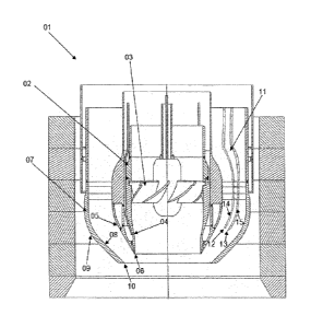
Features of the invention.
1. Burner (01) for a catalytic reactor comprising a central
oxidiser supply tube (02) for providing oxidant flow to a
combustion zone of the reactor with a stationary swirler
element (03), an inner side (04), an outer side (05), an
oxidant inlet and an oxidant nozzle tip (06) and an outer
concentric fuel supply tube (07) for providing fuel flow to
the combustion zone with an inner side (08), an outer side
(09), a fuel inlet and a fuel nozzle tip (10),
the burner further comprises a recycle gas duct (11)
arranged between the oxidiser supply tube and the fuel
supply tube, said recycle gas duct has an inlet, an inner
recycle gas nozzle tip (12) facing the oxidiser supply tube
and an outer recycle gas nozzle tip (13) facing the fuel
supply tube,
wherein the recycle gas duct is arranged so the inner
recycle gas nozzle tip has a distance X from the outer side
of the oxidiser supply tube, and the outer recycle gas
nozzle tip has a distance Y from the inner side of the fuel
supply tube,
where X is large enough to provide fuel flow passage
between the outer side of the oxidiser supply tube and the
inner recycle gas nozzle tip and Y is large enough to
provide fuel flow passage between the inner side of the
fuel supply tube and the outer recycle gas nozzle tip.
2. Burner according to feature 1, wherein said recycle gas
duct is an annular duct comprising two concentric recycle
gas tubes, an inner recycle gas tube with the inner recycle
CA 2913213 2019-07-23
8
gas nozzle tip and an outer recycle gas tube with the outer
recycle gas nozzle tip.
3. Burner according to any of the preceding features,
wherein the distance from the outer side of the oxidiser
supply tube and the lower part of the inner recycle gas
tube is at least X and the distance from the inner side of
the fuel supply tube and the lower part of the outer
recycle gas tube is at least Y.
4. Burner according to any of the preceding features,
wherein X is at least 1 mm and Y is at least 1 mm.
5. Burner according to any of the preceding features,
wherein the recycle gas nozzle tips are arranged in a
distance L up-stream with relation to the fuel flow
direction from the oxidant nozzle tip and the fuel nozzle
tip.
6. Burner according to feature 5, wherein the distance
between the inner recycle gas nozzle tip and the outer
recycle gas nozzle tip is Z, and the distance L is in the
following range: 0 < L < (x+Y+z) x 20.
7. Burner according to feature 5 or 6, wherein the distance
L is large enough to ensure partial mixing of the recycle
gas and the fuel.
8. Burner according to any of the features 5 - 7, wherein
the distance L is large enough to achieve more than 90%
mixture of the recycle gas with the fuel before the fuel
and the recycle gas passes the fuel nozzle tip and reaches
a combustion zone of the catalytic reactor.
CA 2913213 2019-07-23
9
9. Burner according to any of the features 1 - 8, wherein
the fuel is a gaseous hydrocarbon and the recycle gas is a
recycle gas from a Fisher Tropsh synthesis.
10. A method for burning a fuel in a catalytic reactor
comprising the steps of
= providing a first stream comprising oxidant to an
oxidant inlet of a central oxidiser supply tube
comprising an inner and an outer side,
= providing a second stream comprising fuel to a fuel
inlet of an outer fuel supply tube concentric to the
oxidiser supply tube and comprising an inner and an
outer side,
= providing a third stream comprising recycle gas to a
recycle gas inlet of a recycle gas duct arranged
between the oxidiser supply tube and the fuel supply
tube,
= flowing the first stream from the oxidant inlet,
through the central oxidiser supply tube to an oxidant
nozzle tip, inducing a swirl to the first stream by
means of a stationary swirler element mounted in the
central oxidiser supply tube and exiting the first
stream from the oxidiser supply tube via the oxidant
nozzle tip opening,
= flowing the second stream from the fuel inlet, through
the outer fuel supply tube and exiting the second
stream from the outer fuel supply tube via a fuel
outlet between the oxidant nozzle tip and a fuel
nozzle tip of the outer fuel supply tube,
= flowing the third stream from the recycle gas inlet,
through the recycle gas duct and exiting the third
CA 2913213 2019-07-23
10
stream within the flow of the second stream from the
recycle gas duct via a recycle gas outlet between an
inner recycle gas nozzle tip and an outer recycle gas
nozzle tip.
11. A method according to feature 10, wherein the third
stream is partially mixed with the second stream before the
partially mixed third and second stream flows through the
fuel outlet and reaches a combustion zone of the catalytic
reactor.
12. A method according to feature 10 or 11, wherein only
the second stream contacts the outer side of the oxidiser
supply tube and the inner side of the fuel supply tube.
13. A method according to any of the features 10 - 12,
wherein the second stream is gaseous hydrocarbon and the
third stream is a recycle gas from a Fisher Tropsh
synthesis.
14. A method according to any of the features 10 - 13,
wherein the temperature of the second stream is within a
critical metal dusting temperature range and the
temperature of the third stream is outside a critical metal
dusting temperature range and the flow velocity of the
third stream in the recycle gas duct is sufficiently high
to keep the temperature of the recycle gas duct below a
critical metal dusting temperature.
15. A method according to any of the features 11 - 14,
wherein the third stream is sufficiently mixed with the
second stream to avoid soot formation.
CA 2913213 2019-07-23
11
16. Use of a burner according to anyone of the features 1 -
9 for carrying out catalytic processes in a gas fuelled
reactor.
CA 2913213 2019-07-23
12
Position numbers
01. Burner.
02. Central oxidiser supply tube.
03. Stationary swirler element.
04. Inner side of the oxidiser supply tube.
05. Outer side of the oxidiser supply tube.
06. Oxidant nozzle tip.
07. Outer concentric fuel supply tube.
08. Inner side of the fuel supply tube.
09. Outer side of the fuel supply tube.
10. Fuel nozzle tip.
11. Recycle gas duct.
12. Inner recycle gas nozzle tip.
13. Outer recycle gas nozzle tip.
14. Inner recycle gas tube.
15. Outer recycle gas tube.
Fig. 1 shows a cross sectional view of a burner 01
according to an embodiment of the invention. Coaxial with
the centre of the burner is a central oxidiser supply tube
02, comprising an inner wall 04, an outer wall 05 and an
oxidant nozzle tip 06. To create a swirling motion of the
oxidant flowing out of the oxidiser supply tube, a
stationary swirler element 03 is arranged inside the
oxidiser supply tube. Fuel is supplied to the combustion
area via an outer concentric fuel supply tube 07 which has
a fuel nozzle tip 10 arranged slightly lower than the
oxidant nozzle tip. The inner wall of the fuel supply tube
08 is facing the central oxidiser supply tube and the outer
wall of the fuel supply tube 09 is facing the reactor.
CA 2913213 2019-07-23
13
In order to provide recycle process gas to the reactor with
low risk of metal dusting, a recycle gas duct 11 is
arranged within the fuel supply tube, between the inner
wall of the fuel supply tube and the outer wall of the
oxidiser supply tube. Hence, the inner recycle gas tube 14
with the inner recycle gas nozzle tip 12 faces the outer
wall of the oxidiser supply tube; and the outer recycle gas
tube 15, with the outer recycle gas nozzle tip 13, faces
the inner wall of the fuel supply tube.
CA 2913213 2019-07-23