Note: Descriptions are shown in the official language in which they were submitted.
CA 02913482 2015-11-24
FILTER, METHOD FOR PRODUCING FILTER, AND LASER WAVELENGTH
MONITORING APPARATUS
TECHNICAL FIELD
[0001] The present invention relates to the field of optical fiber
communications
technologies, and in particular, to a filter, a method for producing a filter,
and a laser
wavelength monitoring apparatus.
BACKGROUND
[0002] With continuous growth of a user's requirement for bandwidth, a
conventional copper wire broadband access system is increasingly confronted
with a
bandwidth bottleneck. At the same time, an optical fiber communications
technology
with a massive bandwidth capacity is increasingly mature, and an optical fiber
access
network becomes a strong competitor of a next-generation broadband access
network.
In particular, a PON (passive optical network, passive optical network) system
is
more competitive.
[0003] In the PON system, an optical module is used as a physical entity
for
implementing a transceiver system, and a function of the optical module is of
great
importance; a laser is used as a transmission apparatus of a communication
lightwave,
a function of the laser is a top priority. In many application scenarios of a
PON field, a
transmit wavelength of a laser device needs to be stable at a specific value,
so as to
ensure that technical specifications of physical transmission and an optical
communication standard are met. Therefore, in many application scenarios, a
laser in
an optical module generally has a semiconductor cooler or a heating membrane
used
to adjust a wavelength, and a laser wavelength monitoring apparatus needs to
be used
to implement a feedback adjustment.
[0004] As shown in FIG 1, a prior laser wavelength monitoring apparatus
includes a collimation lens 1, a first focusing lens 2, an F-P etalon 3, two
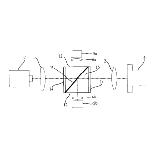
beam
splitters 4a and 4b, two optical receivers 5a and 5b, and two second focusing
lenses 6a
and 6b, where the F-P etalon 3 functions as a comb filter, and the two beam
splitters
4a and 4b each are a beam splitter that has a fixed split ratio. Light emitted
by a laser
CA 02913482 2015-11-24
7 becomes collimated light after passing through the collimation lens 1. The
beam
splitter 4a divides the collimated light according to a specific ratio, where
one part of
the light is received by the optical receiver 5a after passing through the
second
focusing lens 6a, and the other part of the light is incident into the F-P
etalon 3 after
passing through the beam splitter 4a. The beam splitter 4b divides, according
to a
specific ratio, light that penetrates the F-P etalon 3, where one part of the
light is
received by the optical receiver 5b after passing through the second focusing
lens 6b,
and the other part of the light passes through the beam splitter 4b, and then
is incident
into an incident port 8 of a transmit fiber after passing through the first
focusing lens
2.
[0005] It is assumed that PD10 and PD20 are respectively initially
calibrated
optical powers of the two optical receivers 5a and 5b, PD1 and PD2 are
respectively
actual received optical powers of the two optical receivers 5a and 5b, and a
ratio of
the actual received optical power of the optical receiver 5b to that of the
optical
receiver 5a is A=PD2/PD1. When a redshift occurs in a laser wavelength,
PD2=PD20'
+ AP, and when a blueshift occurs in the laser wavelength, PD2=PD20¨AP; PD1
does
not vary with the laser wavelength. Therefore, a wavelength offset is:
AA= +AP/PD10 (redshift), and AA= ¨AP/PD l 0 (blueshift) (1)
[0006] Therefore, a change status of a laser wavelength may be defined
according
to the wavelength offset AA.
[0007] The inventor of the present patent application finds that because
of two
beam splitters, an overall packaging size of a laser wavelength monitoring
apparatus
is relatively large, and packaging costs are relatively high, which does not
accord with
a current development tendency of miniaturization and low costs. In addition,
monitoring precision of a laser wavelength monitoring apparatus of this
structure is
not high enough.
SUMMARY
[0008] Embodiments of the present invention provide a filter, a method
for
producing a filter, and a laser wavelength monitoring apparatus, so as to
reduce a
volume and costs of a laser wavelength monitoring apparatus and further
improve
monitoring precision.
[0009] According to a first aspect of the present invention, a filter is
provided,
2
CA 02913482 2015-11-24
including two translucent bodies, where each of the translucent bodies has a
first
plane, a second plane that forms a wedge angle with the first plane, and a
third plane
that intersects with both the first plane and the second plane, first planes
of the two
translucent bodies are parallel to each other, and second planes of the two
translucent
bodies are parallel to each other;
a beam splitting film, where surfaces of both sides are respectively
combined with the first planes of the two translucent bodies; and
two reflective films, respectively combined with the second planes of the
two translucent bodies.
[0010] In a possible implementation manner of the first aspect, the wedge
angle is
450 =1--- 11, , and A, is a set allowable error.
[0011] In a possible implementation manner of the first aspect, third
planes of the
two translucent bodies are parallel or not parallel.
[0012] In a possible implementation manner of the first aspect, in the
two
translucent bodies, one of the translucent bodies includes at least two
translucent
substrates, where an antireflection coating is disposed between two adjacent
translucent substrates.
[0013] According to a second aspect of the present invention, a method
for
producing the filter according to any one of the foregoing technical solutions
is
provided, including: plating a reflective film separately on second planes of
two
translucent bodies, and plating a beam splitting film on a first plane of one
of the
translucent bodies; and
combining a first plane of the other translucent body with the beam
splitting film.
[0014] In a possible implementation manner of the second aspect, the
combining a
first plane of the other translucent body with the beam splitting film is
specifically:
bonding the first plane of the other translucent body to the beam splitting
film.
[0015] According to a third aspect of the present invention, a laser
wavelength
monitoring apparatus is provided, including two optical receivers and the
filter
according to any one of the foregoing technical solutions, where:
the two reflective films of the filter respectively face a transmit port of a
laser and an incident port of a transmit fiber, and the two third planes of
the filter
3
CA 02913482 2015-11-24
respectively face receive ports of the two optical receivers.
[0016] In a possible implementation manner of the third aspect, the laser
wavelength monitoring apparatus further includes a collimation lens located
between
the transmit port of the laser and the reflective film that is of the filter
and faces the
transmit port of the laser.
[0017] In a possible implementation manner of the third aspect, one side
of the
collimation lens is a plane and is combined with the reflective film that is
of the filter
and faces the side of the collimation lens.
[0018] In a possible implementation manner of the third aspect, the laser
wavelength monitoring apparatus further includes a first focusing lens located
between the incident port of the transmit fiber and the reflective film that
is of the
filter and faces the incident port of the transmit fiber.
[0019] In a possible implementation manner of the third aspect, one side
of the
first focusing lens is a plane and is combined with the reflective film that
is of the
filter and faces the side of the first focusing lens.
[0020] In a possible implementation manner of the third aspect, the laser
wavelength monitoring apparatus further includes two second focusing lenses,
respectively located between the two third planes of the filter and the
receive ports
that are of the optical receivers and face the two third planes of the filter.
[0021] In a possible implementation manner of the third aspect, in the
filter, a
translucent body that includes at least two translucent substrates is located
on one side
that is of a beam splitting film and is close to the incident port of the
transmit fiber.
[0022] In technical solutions of the embodiments of the present
invention, a beam
splitting film is disposed between first planes of two translucent bodies, so
that a
wavelength monitoring optical path of a laser wavelength monitoring apparatus
is
significantly shortened compared with that in the prior art, a volume of the
laser
wavelength monitoring apparatus is relatively small, and miniaturized
packaging can
be implemented, which significantly reduces packaging costs of a product. In
addition, a laser wavelength monitoring apparatus that has a filter can
perform
transmittance power monitoring and reflected power monitoring, and monitoring
precision of a wavelength offset is doubled. Therefore, the laser wavelength
monitoring apparatus has higher monitoring precision compared with that in the
prior
art.
4
CA 02913482 2015-11-24
BRIEF DESCRIPTION OF DRAWINGS
[0023] FIG 1 is a schematic structural diagram of a prior laser
wavelength
monitoring apparatus;
[0024] FIG 2a is a schematic structural diagram of a first
implementation manner
of a filter according to a first embodiment of the present invention;
[0025] FIG 2b is a schematic structural diagram of a second
implementation
manner of the filter according to the first embodiment of the present
invention;
[0026] FIG. 3 is a schematic flowchart of a method for producing a
filter
according to a fifth embodiment of the present invention;
[0027] FIG 4 is a schematic diagram of a process of producing a filter
according
to an embodiment of the present invention;
[0028] FIG 5 is a schematic structural diagram of a laser wavelength
monitoring
apparatus according to a seventh embodiment of the present invention;
[0029] FIG 6 is a schematic structural diagram of a laser wavelength
monitoring
apparatus according to an eighth embodiment of the present invention;
[0030] FIG. 7 is a schematic structural diagram of a laser wavelength
monitoring
apparatus according to a ninth embodiment of the present invention;
[0031] FIG 8 is a schematic structural diagram of a laser wavelength
monitoring
apparatus according to a tenth embodiment of the present invention; and
[0032] FIG. 9 is a schematic structural diagram of a laser wavelength
monitoring
apparatus according to an eleventh embodiment of the present invention.
DESCRIPTION OF EMBODIMENTS
[0033] To reduce a volume and costs of a laser wavelength monitoring
apparatus
and further improve monitoring precision, embodiments of the present invention
provide a filter, a method for producing a filter, and a laser wavelength
monitoring
apparatus. In technical solutions of the embodiments of the present invention,
a beam
splitting film is disposed between first planes of two translucent bodies, so
that a
wavelength monitoring optical path of a laser wavelength monitoring apparatus
is
significantly shortened compared with that in the prior art, a volume of the
laser
wavelength monitoring apparatus is relatively small, and miniaturized
packaging can
be implemented, which makes packaging costs relatively low. In addition, a
laser
5
CA 02913482 2015-11-24
wavelength monitoring apparatus that has a filter can perform transmittance
power
monitoring and reflected power monitoring, and monitoring precision of a
wavelength
offset is doubled. Therefore, the laser wavelength monitoring apparatus
further has
higher monitoring precision compared with that in the prior art. To make the
objectives, technical solutions, and advantages of the present invention more
comprehensible, the following further describes the present invention in
detail by
listing specific embodiments.
[0034] As shown
in FIG. 2a, a filter in a first embodiment of the present invention
includes:
two translucent bodies 9, where each of the translucent bodies 9 has a first
plane 10, a second plane 11 that forms a wedge angle with the first plane 10,
and a
third plane 12 that intersects with both the first plane 10 and the second
plane 11, first
planes 10 of the two translucent bodies 9 are parallel to each other, and
second planes
11 of the two translucent bodies 9 are parallel to each other;
a beam splitting film 13, where surfaces of both sides are respectively
combined with the first planes 10 of the two translucent bodies 9; and
two reflective films 14, respectively combined with the second planes 11
of the two translucent bodies 9.
[0035] The
translucent body 9 may include only one translucent substrate, or may
include two or more translucent substrates. In the embodiment shown in FIG 2b,
in
the two translucent bodies 9, one of the translucent bodies 9 includes at
least two
translucent substrates 16, where an antireflection coating 17 is disposed
between two
adjacent translucent substrates 16. By disposing the antireflection coating
17, a light
loss can be reduced. A material of the translucent substrate 16 is not
limited, and a
material such as glass may be selected and used; a cross-section shape of the
translucent substrate may be a triangle, a trapezoid, or the like.
[0036] To use a
parallel interference resonance mode (including but not limited to
F-P interference and G-T interference) to implement a filtering function, the
first
planes 10 of the two translucent bodies 9 are parallel to each other, and the
second
planes 11 of the two translucent bodies 9 are parallel to each other. The beam
splitting
film 13 has a fixed split ratio, and can divide an incident laser light by
ratio, where
one part is reflected, and the other part penetrates. The beam splitting film
13 may be
first plated on a first plane 10 of one of the translucent bodies 9, and a
first plane 10 of
the other translucent body 9 is then bonded to the beam splitting film 13, so
as to
6
CA 02913482 2015-11-24
ensure that stable parallel interference resonance can be formed in the
filter. The
reflective film 14 generally includes multiple film layers in different
thicknesses that
are alternately distributed. These film layers may be silicon dioxide film
layers,
tantalum dioxide film layers, or the like. Design of a specific structure of
these film
layers is the prior art, and details are not described herein again.
[0037] A specific value of the wedge angle is not limited. In a filter in
a second
embodiment of the present invention, a wedge angle is 45 , where a is a set
allowable error, for example, 1 . By selecting and using a wedge angle in this
value
range, design of an optical path of the filter can be relatively simple and
convenient,
which facilitates a layout of internal mechanical parts of a laser wavelength
monitoring apparatus.
[0038] In a filter in a third embodiment of the present invention, the
third planes
12 of the two translucent bodies 9 are not parallel. In a filter in a fourth
embodiment
of the present invention, the third planes 12 of the two translucent bodies 9
are
parallel. By disposing the third planes 12 of the two translucent bodies 9 in
parallel,
two optical receivers of the laser wavelength monitoring apparatus can be
disposed at
symmetrical positions, which further facilitates design of an optical path and
compactness and miniaturization of a product, and further reduces packaging
costs of
the product.
[0039] As shown in FIG 3 and FIG. 4, a method for producing a filter in a
fifth
embodiment of the present invention includes:
[0040] Step 101: Plate a reflective film separately on second planes of
two
translucent bodies, and plate a beam splitting film on a first plane of one of
the
translucent bodies.
[0041] Step 102: Combine a first plane of the other translucent body with
the
beam splitting film.
[0042] In a method for producing a filter in a sixth embodiment of the
present
invention, step 102 is specifically combining the first plane of the other
translucent
body with the beam splitting film by using a bonding technology. An optical
cement
bonding technology is preferably used. Optical cement bonding is closely
pasting
together two homogeneous or heterogeneous materials after performing a series
of
surface processing, to form optical cement at a room temperature, and then,
performing thermal treatment on the optical cement, to form permanent bonding
in a
7
CA 02913482 2015-11-24
case in which another binder and high pressure are not required. In an aspect
of laser
application, the technology not only can significantly improve thermal
performance
and beam quality that are of a laser, but also facilitates integration of a
laser system.
[0043] As shown in FIG. 5, a laser wavelength monitoring apparatus in a
seventh
embodiment of the present invention includes two optical receivers 5a and 5b
and the
filter 15 according to any one of the foregoing embodiments.
[0044] Two reflective films 14 of the filter 15 respectively face a
transmit port of
a laser 7 and an incident port 8 of a transmit fiber, and two third planes 12
of the filter
respectively face receive ports of the two optical receivers 5a and 5b.
10 [0045] The optical receivers 5a and 5b may use photodiodes to
detect power of a
received laser light.
[0046] Referring to an eighth preferable embodiment shown in FIG 6, the
laser
wavelength monitoring apparatus further includes: a collimation lens 1 located
between a transmit port of a laser 7 and a reflective film 14 that is of a
filter 15 and
15 faces the transmit port of the laser 7, and a first focusing lens 2
located between an
incident port 8 of a transmit fiber and a reflective film 14 that is of the
filter 15 and
faces the incident port 8 of the transmit fiber. The collimation lens 1 and
the first
focusing lens 2 may also be respectively designed in structures of the laser 7
and the
incident port 8 of the transmit fiber. However, in this case, sizes of the
laser 7 and the
incident port 8 of the transmit fiber are relatively large, structures of the
laser 7 and
the incident port 8 of the transmit fiber are slightly complex, and it is also
inconvenient to adjust positions of the collimation lens 1 and the first
focusing lens 2.
[0047] Further referring to the preferable embodiment shown in FIG 6, the
laser
wavelength monitoring apparatus further includes two second focusing lenses 6a
and
6b, respectively located between two third planes 12 of the filter 15 and the
receive
ports that are of the optical receivers 5a and 5b and face the two third
planes 12 of the
filter 15. Similarly and alternatively, the second focusing lenses 6a and 6b
may be
respectively designed in structures of the optical receivers 5a and 5b. It
should be
noted that when areas of receiving surfaces of the optical receivers 5a and 5b
meet a
specific condition, disposing of the second focusing lenses 6a and 6b may be
omitted.
[0048] As shown in FIG. 7, in a laser wavelength monitoring apparatus in
a ninth
embodiment of the present invention, one side of a collimation lens 1 is a
plane and is
combined with a reflective film 14 that is of a filter 15 and faces the side
of the
collimation lens 1. In this case, the laser wavelength monitoring apparatus
has a
8
CA 02913482 2015-11-24
relatively small packaging size, and the position of a first focusing lens 2
may be
adjusted freely.
[0049] As shown in FIG 8, in a laser wavelength monitoring apparatus in a
tenth
embodiment of the present invention, one side of a first focusing lens 2 is a
plane and
is combined with a reflective film 14 that is of a filter 15 and faces the
side of the first
focusing lens 2. In this case, the laser wavelength monitoring apparatus has a
relatively small packaging size, and the position of the collimation lens may
be
adjusted freely.
[0050] As shown in FIG 9, in a laser wavelength monitoring apparatus in
an
eleventh embodiment of the present invention, one side of a collimation lens 1
is a
plane and is combined with a reflective film 14 that is of a filter 15 and
faces the side
of the collimation lens 1, and one side of a first focusing lens 2 is a plane
and is
combined with a reflective film 14 of the filter 15. In this case, a packaging
size of the
laser wavelength monitoring apparatus is the smallest compared with packaging
sizes
of the laser wavelength monitoring apparatuses in the ninth and the tenth
embodiments, and positions of the collimation lens and the first focusing lens
cannot
be adjusted freely.
[0051] In the filter 15, when one of the translucent bodies 9 includes at
least two
translucent substrates 16, to reduce a loss of incident light, the translucent
body 9 that
includes at least two translucent substrates 16 are preferably designed on one
side that
is of a beam splitting film 13 and is close to an incident port 8 of a
transmit fiber.
[0052] The embodiment shown in FIG. 6 is used as an example. A working
principle of the laser wavelength monitoring apparatus is as follows: A laser
light
transmitted by a laser 7 becomes collimated light after passing through the
collimation
lens 1; the collimated light is incident into the reflective film 14 on one
side of the
filter 15, and the beam splitting film 13 divides a received laser light by
ratio, where
one part is reflected and emitted from the filter 15 to the first optical
receiver 5a; the
other part penetrates to the reflective film 14 on the other side of the
filter 15, then, a
part is reflected back to the beam splitting film 13, and the beam splitting
film 13
divides a received laser light by ratio again, where a part is reflected and
emitted from
the filter to the second optical receiver 5b.
[0053] A beam splitting film is disposed between first planes of two
translucent
bodies, so that a wavelength monitoring optical path of a laser wavelength
monitoring
apparatus is significantly shortened compared with that in the prior art, a
volume of
9
CA 02913482 2015-11-24
the laser wavelength monitoring apparatus is relatively small, and
miniaturized
packaging can be implemented, which significantly reduces packaging costs of a
product. For example, a wavelength monitoring apparatus in the prior art
generally
uses XMD packaging, and packaging costs are relatively high. However, a
wavelength monitoring apparatus in the solutions may use TO packaging, which
significantly reduces packaging costs.
[0054] It is assumed that PD1 and PD2 are respectively actual received
optical
powers of two optical receivers 5a and 5b, an overall reflected optical power
of a filter
is Pf, and an overall transmittance optical power of the filter 15 is Pt. When
a
10 redshift occurs in a laser wavelength, the overall transmittance optical
power of the
filter 15 is Pt + AP, and when a blueshift occurs in the laser wavelength, the
overall
reflected optical power of the filter 15 is Pf¨AP; PD1 does not vary with the
laser
wavelength. Therefore, a wavelength offset is:
AA= + 2AP/(Pf+Pt) (redshift), and AA= ¨2AP/(Pf+Pt) (blueshift) (2)
15 [0055] For a filter as a whole, Pf+Pt=PO, where PO is a constant
value, and does
not vary with a laser wavelength. Therefore, a change status of a laser
wavelength
may also be defined according to the wavelength offset AA.
[0056] By comparing formula (2) with formula (1) in the prior art, it
can be seen
that the laser wavelength monitoring apparatus can perform transmittance power
monitoring and reflected power monitoring, and monitoring precision of a
wavelength
offset is doubled. Therefore, compared with a laser wavelength monitoring
apparatus
in the prior art, the laser wavelength monitoring apparatus has higher
monitoring
precision and higher monitoring performance.
100571 Obviously, a person skilled in the art can make various
modifications and
variations to the present invention without departing from the spirit and
scope of the
present invention. The present invention is intended to cover these
modifications and
variations provided that they fall within the scope of protection defined by
the
following claims and their equivalent technologies.