Note: Descriptions are shown in the official language in which they were submitted.
CA 02913725 2015-11-26
1
Blast furnace and process for operating a blast furnace
The present invention relates to a blast furnace and a process for operating a
blast furnace, which may
be employed for reducing CO2 emissions.
Metallurgical plants are plants for processing metal ore, wherein the central
element of such a meta-
llurgical plant is a blast furnace. These metallurgical plants have been known
for a long time. A blast
furnace is fed with raw materials which comprise metal ore, additives and
heating material. Usually
coal or coke is used as a heating material, wherein coal and coke produce heat
by burning in the pres-
ence of air on the one hand and wherein coal and coke also function as
reduction agent for the metal
ore, as the metal ore is basically comprised of metal oxide. When reducing
metal ore in a blast fur-
nace, various gases are produced, which collectively are known as a furnace
gas or flue gas. Said fur-
nace gas usually contains a substantial amount of carbon dioxide (CO2). Carbon
dioxide is a green-
house gas, and during recent years more and more effort has been made to avoid
or convert green-
house gases, as these greenhouse gases are regarded as detrimental for the
climate.
In the field of metal production, it is a general aim to use as few raw
materials and heating materials as
possible, as these materials are expensive and it is expensive to transport
these materials. Much effort
has been made to reduce the amount of coke/coal used in production. One
approach was blowing coal
dust into the blast furnace, and another approach was producing carbon
monoxide as a reduction gas,
either in the blast furnace itself or in a separate gasification reactor
outside the blast furnace. From EP
09318401 Al it is known to blow a portion of the carbon required for reducing
the metal ore into the
blast furnace in form of a substitute reduction material. In this sense, e.g.
natural gas, heavy oil, fine
coal and similar material having a high carbon content may be used as a
substitute reduction ma-terial.
These materials may be directly blown into the blast furnace shaft or may be
gasified outside of the
blast furnace shaft in a separate gasification reactor so as to form a
reduction gas. Subsequently, such a
reaction gas may be directed into the blast furnace shaft. The method known
from EP 09318401 Al
may provide a possibility to reduce the consumed amount of coal or coke and
may also provide a
possibility to use materials, which are difficult to process as a substitute
reduction mate-rial, however,
the problem of high CO2 production in metal production has not been solved.
The prior art discloses methods wherein furnace gas or a particular component
thereof is directed out
of the blast furnace shaft and, after being processed in a CO2 converter, is
re-directed into the blast
furnace shaft. EP 2 543 743 Al discloses a method wherein furnace gas is
directed out of the blast
furnace shaft and is directed to a separation device in which CO and CO2 are
separated. Only the
separated CO2 is subjected to reforming in a CO2 converter. Reforming produces
mainly CO and H20,
wherein 1120 is separated and CO is directed into the blast furnace shaft. WO
2011/087036 Al also
2
discloses a method wherein first furnace gas is directed to a separation
device in which CO and CO2 are
separated. In a CO2 converter, the CO2 is converted into 02 and CO. The CO
from said conversion and
the previously separated CO are jointly directed into the blast furnace shaft.
US 3 909 446 A discloses a
method wherein furnace gas from a blast furnace shaft is mixed with coke oven
gas in a CO2 converter.
Thus, a gas mixture comprising CO and H2 is produced which is re-directed into
the blast furnace shaft.
WO 2010/049536 Al describes a similar method wherein also carbon containing
particles are re-directed
into the blast furnace shaft. US 2 598 735 A discloses a method wherein
furnace gas from a blast furnace
shaft is mixed with carbon/coal and oxygen in a gas generator. A portion of
the carbon is burnt in
presence of the oxygen, and another portion of the carbon reduces the CO2 from
the furnace gas and the
CO2 from the burnt carbon to CO. Said CO is re-directed into the blast furnace
shaft as a reducing agent.
None of these documents discloses a method wherein further processing of a
portion of the converted CO
is carried out.
The present invention is directed to a blast furnace and a process for
operating a blast furnace, which
are able to reduce the CO2 production as well as to reduce the amount of
consumed additives and
heating material when compared to presently used metal production plants.
This problem is solved by a method for processing metal ore comprising the
following steps: reducing a
metal ore, and thereby producing furnace gas containing CO2 in a blast furnace
shaft; discharging said
furnace gas from the blast furnace shaft; directing at least a portion of the
furnace gas directly or indirectly
into a CO2 converter and reducing the CO2 contained in the furnace gas to CO
in the CO2 converter,
wherein the step of reducing CO2 to CO is carried out inside the CO2 converter
by addition of C at a
temperature in the region of 800 C to 1700 C; directing a first portion of the
CO from the CO2 converter
into the blast furnace shaft; directing a second portion of the CO from the
CO2 converter into a further
processing process, wherein the further processing process comprises a
conversion process converting
synthesis gas into a functionalized or non-functionalized hydrocarbon, wherein
the synthesis gas is
produced by the following steps (i) decomposing a fluid containing
hydrocarbons into carbon and
hydrogen by at least one of a plasma process and the introduction of theimal
energy; and
(ii) mixing at least a portion of the hydrogen (1-12) with at least a portion
of the CO produced in the CO2
converter.
In accordance with a further aspect of the present invention, there is
provided a blast furnace for metal
production from metal ore which comprises: a blast furnace shaft adapted for
reducing metal ore having
feeder for metal ore located at the upper end of the blast furnace shaft, a
first furnace gas outlet and at least
one CO inlet; a CO2 converter, which comprises a CO2 converter inlet and a CO2
converter gas inlet for
gases containing CO2 and which is adapted to reduce CO2 to CO by addition of C
at a temperature of
between 800 C and 1700 C; wherein the first furnace gas outlet is directly or
indirectly connected to the
CO2 converter gas inlet; wherein the CO2 converter comprises at least one
first CO outlet for discharging a
Date Recue/Date Received 2020-07-02
2a
first portion of the CO produced in the CO2 converter, wherein said first CO2
outlet is directly or indirectly
connected to the blast furnace shaft ; wherein the CO2 converter comprises at
least one second CO outlet
for discharging a second portion of the CO to a further processing converter
which is adapted to produce
functionalized or non-functionalized hydrocarbons from a synthesis gas; and a
hydrocarbon converter
operated by means of a plasma or by means of theimal energy, wherein the
hydrocarbon converter
comprises at least one hydrocarbon inlet for a fluid containing hydrocarbons
as well as at least one outlet
for at least carbon; and wherein at least one of the outlets for at least
carbon is connected to the CO2
converter inlet of the CO2 converter (4).
The method for processing metal ore disclosed herein comprises the following
steps: reducing a metal
ore, particularly reducing metal oxides; producing a furnace gas in a blast
furnace shaft, wherein the
furnace gas contains CO2; and discharging the furnace gas from the blast
furnace shaft; directing at least a
portion of the furnace gas directly or indirectly to a CO2 converter and
reducing the CO2 contained in the
furnace gas in said CO2 converter so as to produce CO; and directing at first
portion of said CO from the
CO2 converter into the blast furnace shaft. This method solves the above
identified problem and also
produces CO as a gaseous reduction material, which may be easily fed into the
blast furnace shaft.
Further, a second portion of the CO is directed from the CO2 converter to the
further processing process.
Depending on the type of CO2 converter, the step of converting CO2 into CO
produces more CO than
necessary for reducing metal ore in the blast furnace shaft. The additionally
produced CO may be used as
feed stock or energy carrier in the further processing process.
According to one embodiment of the method, the second portion of the CO from
the CO2 converter is
first burned so as to foul' an exhaust gas mixture containing CO2 before it is
directed in form of said
exhaust gas mixture into a further processing process. In this way, the CO may
be used as an energy
Date Recue/Date Received 2020-07-02
CA 02913725 2015-11-26
3
carrier. Depending on the type of the further processing process, it may be
desirable, to have the CO2
as a feed stock or raw material.
According to another embodiment of the method, wherein the furnace gas is
indirectly routed to the
CO2 converter, the furnace gas is first burned so as to form an exhaust gas
mixture containing CO2,
before it is directed into the CO, converter in form of said exhaust gas
mixture. In the CO2 converter,
the CO2 is reduced to CO. Thus, the CO contained in the furnace gas and other
combustible
components of the furnace gas may be used as an energy carrier.
Depending on the type of the further processing process, it may be
advantageous to direct a portion of
the exhaust gas mixture containing CO2 not through the CO2 converter but to a
further processing
process, wherein the CO, may serve as raw material or feed stock in said
further processing process.
In one embodiment of the method, a portion of the furnace gas is directly
routed to a further
processing process, i.e. bypassing the CO2 converter. Thus, a higher amount of
CO2 may be provided
to the further processing process. It is also possible to set a desired ratio
of CO content to CO2 content
in a gas mixture for the further processing process.
Preferably, a portion of the CO is injected in a lower region of the blast
furnace shaft above the level
of the molten metal, particularly in a region of the blast nozzles or tuyeres.
Thus, CO may be injected
into the reduction zone of the blast furnace shaft as a gaseous reduction
material. Furthermore, when
retrofitting or adapting an existing blast furnace for the method of the
present disclosure, the tuyeres,
that are already present, may be used as CO inlets.
A portion of the CO may preferably be injected at one or more CO inlets along
the height of the blast
furnace shaft. Thus, the location of the different zones of the blast furnace
shaft may be controlled, and
the metal production may be precisely controlled.
The CO inlets may optionally be located partially below the level of the
molten metal in the blast
furnace shaft. Thus, even reduction of the molten metal may be achieved.
In one embodiment of the method, additional carbon may be introduced in the
lower region of the
blast furnace shaft so as to come into contact with the molten metal. Thus,
the melting point of the
metal may be lowered.
In one embodiment of the disclosed method, the step of reducing CO2 to CO in
the CO2 converter is
carried out by addition of C at a temperature between 800 and 1700 C. Under
these conditions a
CA 02913725 2015-11-26
4
Boudouard equilibrium may be achieved, where a high proportion of the
introduced CO2 is converted
into CO.
According to one embodiment of the disclosed method, the further processing
process is one of the
following a) a combustion process in a gas engine or a gas turbine; b) an
oxidation process in a fuel
cell. By means of such processes, heat or mechanical energy may be obtained
from the combustible
CO gas.
According to another embodiment of the disclosed method, the further
processing process is a
biological conversion process in a bio converter, wherein said biological
conversion process is carried
out by using microbes or algae according to one or more of the following net
equations:
a) 6C0 +3 H20 ¨> C2H5OH +4 CO2; b) 6 H2 +2 CO2 ¨> C1150H + 3 1120;
c) 2 CO + 4 fl? C2-150H + 1120. In this way, CO and particularly the
undesirable CO2 may be
converted into Ethanol by addition of hydrogen. Also kerosene, Diesel,
gasoline, methanol or other
fuels may be produced if appropriate microbes and algae are chosen. In this
embodiment the further
processing process is a biological conversion process in a bio converter. By
use of microbes or algae,
the introduced gases CO and CO? are converted into kerosene, diesel, gasoline,
methanol or other fuels
as an end product.
In case the further processing process is a biological conversion process, the
disclosed method
preferably comprises the following steps: decomposing a hydrocarbon containing
fluid into carbon and
hydrogen a) by means of a plasma or b) by introducing thermal energy, wherein
the step of
decomposing is preferably carried out in a separate hydrocarbon converter; and
directing the hydrogen
(H2) to the biological conversion process. In this way, hot carbon is provided
for reducing the CO,
contained in the furnace gas or in the exhaust gas mixture of the combustion
machine at the
Boudouard equilibrium. Furthermore, considerable amounts of hydrogen are
produced which
facilitates that the biological conversion process produces a large amount of
ethanol and little or no
CO2.
According to another embodiment of the disclosed method the further processing
process is a
conversion process, in which a synthesis gas is converted into a
functionalised and/or non-
functionalised hydrocarbon, preferably into paraffin, kerosene, Diesel,
gasoline, liquid gases or
methanol. In this way, a vendible product may be produced from the CO gas,
which is produced in
great amounts.
In the embodiment of the disclosed method, in which the further processing
process is a conversion
process for converting a synthesis gas, the synthesis gas is preferably
produced by the following steps:
CA 02913725 2015-11-26
decomposing a hydrocarbon containing fluid into carbon (C) and hydrogen (H,)
a) by means of plasma
or b) by means of introducing thermal energy; and mixing at least a portion of
said hydrogen (H2) with
at least a portion of the CO produced in the CO2 converter. In this way great
amounts of hydrogen may
be provided. Preferably, the hydrocarbon containing fluid is an inexpensive
fluid, such as CH4, crude
5 oil or other heavy oils.
In the disclosed method, the mass flows of furnace gas, exhaust gas, C, CO
gas, H2 gas, CO2 gas may
be ideally utilized if a plurality of different further processing processes
is carried out.
.. In an alternative form of the disclosed method, the step of reducing CO2 to
CO in the CO2 converter
occurs by means of a Reverse-Water-Shift reaction according to the equation
CO, + H, ¨> CO + H20.
In this way, the CO2 emission of the blast furnace process may be reduced, and
this alternative form
does not produce additional mass flow of CO gas.
In one embodiment, the blast furnace shaft and/or the CO2 converter may be
additionally heated. In the
disclosed method, heating of the blast furnace shaft by means of coke/coal may
be reduced or even
avoided. Therefore, the thermal energy in the blast furnace shaft may not be
sufficient for achieving
sufficiently high temperatures in every situation. By means of additional
heating, higher temperatures
may be achieved, i.e. temperatures required for reducing metal ore and for
melting said metal.
Additional heating is preferably carried out at least partially by means of
heat produced in one of the
above mentioned combustion steps and/or by means of heat produced in one of
the above mentioned
steps of decomposing a hydrocarbon containing fluid into carbon (C) and
hydrogen (H2) a) by means
of a plasma orb) by introducing thermal energy and/or additional heating is
carried out by means of
heat produced during conversion of CO or synthesis gas into funetionalised or
non-functionalised
hydrocarbons. In this way, the heat produced during the decomposition step may
be utilized in a
process step onsite which has a constant demand for heat energy. Accordingly
the heat energy is not
wasted.
The blast furnace for metal production described herein comprises: a blast
furnace shaft having a first
furnace gas outlet and at least one CO inlet; a CO2 converter for reducing CO2
to CO, the CO2
converter comprising a CO2 converter inlet and a CO2 converter gas inlet for
gases containing CO2;
wherein the furnace gas outlet is directly or indirectly connected to the CO,
converter gas inlet; and
wherein the CO2 converter comprises at least one first CO outlet for
discharging a first portion of the
CO produced in the CO2 converter, wherein the first CO outlet is directly or
indirectly connected to the
blast furnace shaft. This blast furnace solves the above mentioned problem
and, further, is able to
produce CO as a gaseous reduction material which may be easily fed into the
blast furnace shaft.
CA 02913725 2015-11-26
Further, the CO, converter comprises at least one second CO outlet for
discharging a second portion of
the CO to a further processing converter. Depending on the type of CO2
converter, the conversion of
CO2 results in having more CO than is necessary for reduction of metal ore in
the blast furnace shaft.
The additionally produced CO may accordingly be diverted as a second portion
of CO, and said
5 second portion of CO may be used in a further processing process as a
feed stock or energy carrier.
According to one embodiment, the blast furnace further comprises a combustion
machine having a
combustion gas inlet and at least one exhaust gas outlet for discharging an
exhaust gas mixture
containing CO2. At least one of the second CO outlets of the CO, converter is
connected to the
combustion gas inlet of the combustion machine. The combustion machine is
operated at least
partially with CO coming from the CO, converter. One of the exhaust outlets of
the combustion
machine is connected to a further processing converter. In the combustion
machine, the CO produced
in the CO2 converter may be used as an energy carrier. Depending on the type
of the further processing
process, it may be desirable to provide an exhaust gas mixture from the
combustion machine, wherein
the CO, is used as feed stock for the further processing process.
In one embodiment, the blast furnace also comprises a combustion machine
having a combustion gas
inlet and at least one exhaust gas outlet for discharging an exhaust gas
mixture containing CO2. This
embodiment comprises an indirect connection of the furnace gas outlet and the
CO, converter, and the
first furnace gas outlet of the blast furnace shaft is connected to the
combustion gas inlet of the
combustion machine. The combustion machine is at least partially operated with
the furnace gas.
Thus, the CO and other combustible components of the furnace gas may be used
as an energy carrier.
In this
CA 02913725 2015-11-26
6
embodiment, preferably one of the exhaust outlets of the combustion machine is
connected to the CO2
converter gas inlet of the CO, converter so as to direct a portion of the
exhaust gas mixture containing
CO2 into the CO2 converter.
Depending on the type of the further processing process, it may be
advantageous that one of the ex-
haust outlets of the combustion machine is connected to the further processing
converter so as to direct
a portion of the exhaust gas mixture containing CO2 past the CO2 converter,
i.e. not through the CO2
converter, and into the further processing process. In this way, a greater
amount of CO2 may be pro-
vided for the further processing process. It is also possible to adjust a gas
mixture having a desired
ratio of CO to CO2 adapted for the further processing process.
When reducing CO2 contained in the furnace gas or in the exhaust gas of the
combustion machine in
the CO2 converter by means of C, it is preferred to connect at least one of
the second CO outlets of the
CO, converter to a further processing converter. In the further processing
converter, the portions of
produced CO, which cannot be redirected into the blast furnace shaft and
accordingly cannot be con-
sumed in the blast furnace shaft, may be converted into heat, into mechanical
power or into sellable
products. The heat and/or the mechanical power may be used for operating the
blast furnace. The
products may be sold.
Depending on the type of the further processing process, it may be
advantageous that the furnace
comprises a second furnace gas outlet, which is directly connected to the
further processing converter,
i.e. having a connection bypassing the CO2 converter. The furnace gas contains
CO and CO2 compo-
nents, wherein these components may be particularly further processed in a
further processing con-
verter having a biological principle.
Preferably, the blast furnace comprises a CO inlet in a lower region of the
blast furnace shaft above
the level of the molten material, particularly in a region of the blast
nozzles or tuyeres. In this way, the
CO may be injected into the reduction zone of the blast furnace shaft as a
gaseous reduction material.
If an existing furnace is retrofitted for the presently disclosed method, the
already existing tuyeres may
be used as CO inlets.
The furnace preferably comprises a plurality of CO inlets at different heights
of the blast furnace shaft.
Thus, CO gas may be injected into different regions along the height of the
blast furnace shaft. Thus,
the location of the different zones of the blast furnace shaft may be
controlled and the metal produc-
tion may be easily controlled.
CA 02913725 2015-11-26
7
Optionally, the CO inlets may be partially located at a height which is below
the level of the molten
metal in the blast furnace shaft during the operation of the furnace.
Accordingly, reduction may be
also achieved in the molten metal, if necessary.
Furthermore, the blast furnace optionally comprises a C inlet for carbon in
the lower region of the
blast furnace shaft, wherein the C inlet is located in such a way that carbon
(C) may be fed into the
blast furnace shaft below the level of the molten metal during operation of
the blast furnace so as to
lower the melting point of the metal.
In one embodiment of the blast furnace, the CO, converter is adapted to reduce
CO, to CO by addition
of C at a temperature between 800 and 1700 C. Under these circumstances a
region of the Boudouard
equilibrium may be reached, where a high proportion of the introduced CO2 is
converted into CO. This
embodiment is advantageous if already hot carbon (C) is available, e.g. from a
hydrocarbon converter.
According to one embodiment of the furnace, the further processing converter
is a gas engine, a gas
turbine or a fuel cell. By means of these machines, heat or mechanical power
may be generated from
the combustible CO gas.
According to another embodiment of the furnace, the further processing
converter is a bio converter in
which a conversion process using microbes or algae is carried out according to
one or more of the
following net equations: a) 6C0 + 3 H,0 C2H5OH + 4 CO2; b) 6 H2 2CO2 C2H5OH
+ 3 H20;
c) 2 CO + 4 H2 C2H5011 H20. In this way, CO and particularly the undesirable
CO2 may be con-
verted into ethanol by addition of hydrogen. Also kerosene, diesel, gasoline,
methanol or other fuels
may be produced by choosing appropriate microbes or algae. In this embodiment
the further pro-
cessing converter is a bio converter, in which a conversion process is carried
out by use of microbes or
algae so as to produce kerosene, diesel, gasoline, methanol or other fuels.
The blast furnace preferably comprises a hydrocarbon converter operated by
means of plasma or ther-
mal energy. The hydrocarbon converter comprises at least one hydrocarbon inlet
for a fluid containing
hydrocarbons and at least one C outlet for at least a carbon and at least one
H2 outlet for hydrogen
(117), wherein at least one of the C outlets for at least carbon is connected
to the CO2 converter inlet.
E.g. inert gases, such as argon or nitrogen may be used as a plasma gas. On
the other hand, hydrogen
gas H2, CO or synthesis gas may be used as plasma gas, as these gases are
produced during the com-
position of said hydrocarbons anyway. Thus, hot carbon is produced for a
reduction of the CO2 con-
tamed in the furnace gas or in the exhaust gas mixture of the combustion
machine in a Boudouard
equilibrium.
CA 02913725 2015-11-26
8
Advantageously, one of the 1-12 outlets for hydrogen (H,) of the hydrocarbon
converter is connected to
the further processing converter. In this way, considerable amounts of
hydrogen are provided, thus
facilitating that the biological conversion produces a large amount of ethanol
and little or no CO2.
In one embodiment of the blast furnace, the further processing converter is a
CO converter, which is
adapted to produce functionalised and/or non-functionalised hydrocarbons from
a synthesis gas. These
hydrocarbons are preferably paraffin, kerosene, diesel, gasoline, liquid gases
or methanol. In this way,
a sellable product may be produced from the great amounts of generated CO gas.
In this embodiment,
the synthesis gas is preferably a mixture of hydrogen produced in the
hydrocarbon converter and CO
produced in the CO2 converter.
The produced mass flows of furnace gas, exhaust gas, C, CO gas, H2 gas, CO2
gas may be ideally con-
verted if the blast furnace comprises a plurality of further processing
converters, which may be simul-
taneously operated.
In an alternative form of the blast furnace, the CO2 converter is adapted to
carry out the reduction of
CO2 into CO by means of a Reverse-Water-Shift reaction according to the
equation
CO2 + 112 ¨4 CO + H20. The Reverse-Water-Shift reaction produces a C0/1-120
mixture. In this em-
bodiment the CO2 emissions may be reduced, and no excess streams of CO gas are
produced. In this
embodiment of the blast furnace, a device for separating water from the CO/H20
mixture is located in
flow direction of the CO/H20 mixture downstream of the CO outlet of the CO?
converter. In this em-
bodiment the blast furnace further comprises a hydrocarbon converter operated
by means of a plasma
or by means of thermal energy, wherein the hydrocarbon converter comprises at
least one hydrocarbon
inlet for a fluid containing hydrocarbons as well as one C outlet for at least
carbon and at least one H,
outlet for hydrogen (H2). At least one of the H2 outlets for hydrogen (H2) is
connected to the CO2 con-
verter inlet. Thus, great amounts of hydrogen may be provided for reducing the
CO2 from the blast
furnace shaft.
Preferably, the blast furnace comprises an auxilliary heater, which is adapted
to heat a reduction zone
and/or melting zone of the blast furnace shaft. By means of additional
heating, high temperatures may
be achieved in every situation, as high temperatures are necessary for
reducing the melting ore and for
melting the metal.
The auxiliary heater preferably uses heat energy, which is produced a) in one
of the above mentioned
combustion machines and/or b) in a further processing converter, which is a
combustion machine or a
CO converter and/or c) heat energy produced in a hydrocarbon converter
operated by means of plasma
or thermal energy, as was mentioned above.
CA 02913725 2015-11-26
9
The advantages of the blast furnace and the method for processing metal ore
are at least the following.
Comparatively less or no coal or coke is used. Therefore, significantly less
or no ash is produced, and
accordingly less or no additives are necessary. In this way expenses for
transport and raw materials
may be reduced, and the pig iron has better quality. Furthermore, less or no
slag is produced. It is not
necessary that slag swims on the molten pig metal because there is a reducing
protective atmosphere
inside the blast furnace shaft.
A basic idea of the presently disclosed blast furnace and methods for
processing metal ore is to reduce
the carbon dioxide from the furnace gas to carbon monoxide. The reduction gas
used in the metallur-
gical process comes entirely from the blast furnace shaft itself and is not
separately produced, such as
e.g. in EP 09318401 Al. Another basic idea is that the carbon dioxide from the
furnace gas may be
used as a synthesis product or synthesis raw material for producing a
synthetic sellable product partic-
ularly for producing hydrocarbons, as will be described in detail below.
The invention and further details and advantages thereof will be discussed in
the following with refer-
ence to the proof read embodiments and with reference to the attached figures.
Fig. 1 is a schematic illustration of a blast furnace according to a
first embodiment;
Fig. 2 is a schematic illustration of a blast furnace according to a second
embodiment;
Fig. 3 is a schematic illustration of a blast furnace according to a
third embodiment;
Fig. 4 is a schematic illustration of a blast furnace according to a
fourth embodiment;
Fig. 5 is a schematic illustration of a blast furnace according to a
fifth embodiment; and
Fig 6 is a schematic illustration of a hydrocarbon converter which may
be used in a blast furnace
according to one of the first to fifth embodiments.
Detailed Description
In the following specification, the terms top, bottom, right and left as well
as similar terms relate to the
orientations and arrangements, respectively, shown in the figures and are only
meant for describing the
embodiments. These terms may refer to preferred arrangements but are not meant
to be limiting.
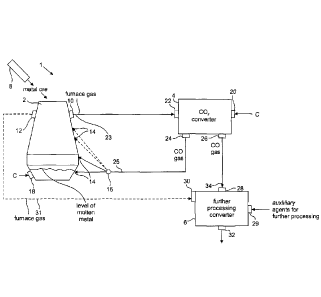
Fig. 1 shows a schematic illustration of a blast furnace 1 comprising a blast
furnace shaft 2, a CO,
converter 4 and a further processing converter 6. A feeder 8 is located at the
upper end of the blast
furnace shaft 2, wherein the feeder is adapted to feed raw material or feed
stock into the blast furnace
shaft 2. Specifically, the raw material is metal ore, possibly necessary
additives, reduction material and
combustible material for heating or initially heating the blast furnace.
CA 02913725 2015-11-26
Seen from top to bottom, the blast furnace shaft 2 comprises an inlet zone for
drying and preheating, a
reduction zone, a carbonisation zone and a melting zone. In the drying and
preheating zone the raw
material is dried and preheated. In the reduction zone, the metal ore,
primarily consisting of metal
5 oxide, will be reduced by CO and C. In the carbonisation zone, a metal
carbon mixture is formed
wherein the melting point of the metal carbon mixture is between 1000 and 1300
C, depending on the
metal. In the melting zone, the metal carbon mixture, particularly an iron
carbon mixture, is molten by
the heat from burning heating material (e.g. coke, combustible gases, furnace
gas etc.) or by means of
an auxiliary heater. The raw metal is collected at the bottom of the blast
furnace shaft 2. During metal
10 production of the metal ore, a gas mixture is formed in the blast
furnace shaft 2. This gas mixture is
referred to as furnace gas or flue gas. Due to the heat of the furnace gas of
around 150 to 250 C, the
furnace gas rises to the top of the blast furnace shaft 2.
In a prior art blast furnace process, the furnace gas has a varying
composition consisting of nitrogen
(1\7, ca. 52-59%), carbon dioxide (CO2, ca. 22-24%), carbon monoxide (CO,
ca.18-21%) and hydrogen
(H2, ca. 1-3%) and water steam and possibly traces of methane (CH4). The
nitrogen and a portion of
the oxygen result from air blown into the furnace shaft. Carbon dioxide,
carbon monoxide and hydro-
gen are generated by chemical reactions during operation of the blast furnace,
wherein these chemical
reactions are well known to the skilled person and are not described in
detail.
In the blast furnace process of the present disclosure, it is considered to
blow a greater amount of air
into the blast furnace shaft during a preheating phase. As soon as a stable
operation of the blast fur-
nace 1 is achieved, no considerable amount of air will be blown into the blast
furnace shaft 2. Since no
air enters the blast furnace shaft 2 from outside, there is accordingly no
nitrogen and no oxygen inside
the blast furnace shaft 2 during a stable operation. Accordingly, the furnace
gas of the present disclo-
sure contains basically no nitrogen during a stable operation. Rather, the
furnace gas has a variable
composition of carbon dioxide (CO2, ca. 50-53%), carbon monoxide (CO, ca. 42-
46%) and hydrogen
(H2, ca. 2-6%) as well as water steam (H20; depending on the residual humidity
of the metal ore and
the additives) and possibly traces of Methane (CH4). The gases CO2 and CO are
formed during chemi-
cal conversion of the ore. CO2 and CO may also be formed from the additives.
In a practical embodi-
ment the ratio of CO to CO2 in the furnace gas is variable and dependson the
construction of blast
furnace, on the composition of the iron ore (Fe2O3 and/or Fe304), on the
process parameters etc.
It should be noted that also in the blast furnace process of the present
disclosure, comparably small
amounts of air, and therefore also some oxygen and nitrogen, may enter into
the blast furnace shaft 2.
These small amounts of air may enter through leaks in the blast furnace shaft
2 or leaks in pipes or
conduits or by means of auxiliary processes (e.g. by means of an auxiliary
heater etc.). However, these
CA 02913725 2015-11-26
11
amounts are very low and may be neglected for the blast furnace process of the
present disclosure.
Nitrogen is an inert gas and does not participate in any of the described
chemical reactions. The
amount of oxygen, which might result from a possibly minor amount of air
entering into the process,
may be neglected when compared to the amount of oxygen which is already
present in the metal ore
(which is metal oxide). Therefore, these minor portions of gases will be
neglected for the following
description.
Both in the classical blast furnace process and in the blast furnace process
of the present disclosure,
also dust particles and other pollutions are contained in the furnace gas.
These pollutions are filtered
out by a dust catcher or filter so as to avoid pollution of other elements of
the blast furnace. A dust
catcher is well known to the skilled person and will not be described in
detail.
Furthermore, it should be noted that the described gases (CO gas, CO2 gas, H2
gas etc.) are, in fact, gas
mixtures. In the following description, the gases will be named after their
main constituent or their
.. chemical active constituent so as to be better distinguishable. It will be
obvious that the gases also may
comprise admixtures or pollutions, which do not have an effect on the
described process. Furthermore,
these gases may also contain chemically inactive components, such as the
nitrogen mentioned above.
As an example the CO gas according to the present description may consist of
90% carbon monoxide,
but also up to 10% of other constituents. Carbon monoxide (CO) is combustible
in the presence of
oxygen. When a gas mixture having 90% carbon monoxide, 5% nitrogen and 5% CO,
(such a mixture
would be termed as CO gas) is burned, nitrogen and CO, would not be part of
the oxidation reaction
and would therefore be chemically inactive constituents.
A first furnace gas outlet 10 and an optional second furnace gas outlet 12 are
located at the top of the
blast furnace shaft 2. Different amounts of furnace gas may be exhausted from
the furnace gas outlets
10, 12 during operation. Furthermore, a plurality of CO inlets 14 is provided
at different heights of the
blast furnace shaft 2. Gaseous carbon monoxide may be blown into the blast
furnace shaft 2 at differ-
ent heights via the CO inlets 14. A divider unit 16 is provided for directing
one or more streams of CO
to the CO inlets 14 at different heights. The divider unit 16 comprises e.g.
valves, shutters and pipes,
which are not shown in detail. At least one of the CO inlets14 is located at a
lower region of the blast
furnace shaft 2 above the level of the molten metal established during the
operation. Particularly, the
CO inlets 14 are located in the region of the blast nozzles or tuyeres in a
prior art blast furnace shaft.
In case an existing blast furnace shall be retrofitted for the process of the
present disclosure, the exist-
ing tuyeres of the blast furnace shaft may be used as CO inlets 14.
Furthermore, at least one of the CO
inlets 14 may be optionally provided at a height below the level of the molten
metal during the opera-
tion of the blast furnace 1.
CA 02913725 2015-11-26
12
A C inlet 18 is located at the lower region of the blast furnace shaft 2.
During the operation, carbon
(C) may be fed into the blast furnace shaft via the C inlet 18 below the level
of the molten metal so as
to lower the melting point of the metal. Alternatively or additionally, a C
inlet 18 may be located in
the region of the reduction zone wherein carbon in powder form may be blown in
via the C inlet 18 so
as to lower the melting point of the metal reduced at this point in time.
The CO2 converter 4 comprises a CO2 converter inlet 20, a CO2 converter gas
inlet 22, a first CO out-
let 24 and a second CO outlet 26. The CO2 converter gas inlet 22 is directly
connected to the first fur-
nace gas outlet 10 of the blast furnace shaft 2 by means of a first furnace
gas conduit 23. In the follow-
ing description, also embodiments having an indirect connection between the
CO2 converter gas inlet
22 and the furnace gas outlet 10 will be described with reference to Fig. 2
and Fig.4.
In the following specification and in the claims, the terms "direct" and
"indirect" and similar terms
will be used, such as "directly connected". In this context the term "direct"
means that a substance or
material will be directed from one element of the blast furnace 1 to another
element without any pro-
cessing or converter in between. Accordingly, the term "indirect" means that a
substance is routed
from one element to another element wherein the substance is processed or
converted between said
elements.
In the embodiment of Fig. 1, the CO, converter 4 comprises a first CO outlet
24 and a second CO out-
let 26. Alternatively, the CO, converter could comprise only one CO outlet 24
or 26, wherein a divider
(not shown) is located downstream of said CO outlet 24 and/or 26, wherein said
divider is able to
route any desired portions of the CO flow produced in the CO, converter to
different other converters
or elements of the blast furnace 1. Furthermore, it is possible that the CO2
converter 4 comprises a
plurality of first CO outlets 24, which lead e.g. to a plurality of CO inlets
14 or to a plurality of divider
units 16. Notwithstanding the above, the CO2 converter 4 may comprise a
plurality of second CO out-
lets 26, which lead to a different further processing converter 6.
The CO, converter 4 may be any suitable CO2 converter which is able to produce
carbon monoxide
(CO) from carbon (C) and carbon dioxide (CO2). In the embodiment of Fig. 1,
the CO2 converter 4
operates according to a part reaction of a known reaction in a blast furnace,
wherein said part reaction
takes place at temperatures between 750 C and 1200 C without the necessity of
a catalyst. Preferably,
the CO2 converter 4 operates at a temperature between 800 C and 1200 C. The
operating temperature
of the CO, converter 4 may be chosen depending on the temperature of the
introduced materials (i.e.
furnace gas, exhaust gas mixture containing CO2, carbon). If the introduced
substances or materials
have a high temperature, then the operating temperature of the CO, converter 4
may also be high. As
was discussed above, in the blast furnace process of the present disclosure,
the furnace gas directed
CA 02913725 2015-11-26
13
into the CO2 converter 4 primarily consists of carbon monoxide (CO) and carbon
dioxide (CO2). In the
CO2 converter 4, the CO is directed over hot carbon or is mixed with hot
carbon (and possibly with
hydrogen) so as to be converted according to the following chemical reaction:
CO, + C ¨> 2 CO
The carbon C introduced into the CO2 converter 4 may simply be delivered from
a storage container.
In the following description with respect to Fig 4, an embodiment will be
discussed wherein hot car-
bon C is produced in a hydrocarbon converter and is directed into the CO2
converter. The CO2 con-
verter 4 operates best at the Boudouard-Equilibrium. At temperatures around
800 C, about 94% car-
bon monoxide will be provided, and at temperatures of around 1000 C, about 99%
carbon monoxide
will be provided. Furthermore, residual water, which may be present as
residual humidity in the metal
ore or in the additives, may be present in the form of water steam (1420) and
will be converted in the
CO, converter according to the following reaction:
C + H2O ¨> CO + H2
The other components of the furnace gas (CO and possibly traces of N2, H2 and
CH4), which are also
directed into the CO, converter, are not part of a chemical conversion.
The gas mixture discharged from the CO, converter 4 is actually a synthesis
gas having a low hydro-
gen content, wherein said synthesis gas is directed into the further
processing converter. The hydrogen
content depends on the humidity of the metal ore or on the additives and on
the amount of hydrogen
which is possibly mixed with the carbon. The gas mixture primarily consists of
CO gas, wherein a
portion of the CO was already present as a constituent of the furnace gas, and
wherein the rest of the
CO results from the conversion of CO, contained in the furnace gas inside the
CO2 converter 4.
The further processing converter 6 is a device, which is able to process CO
and CO2 alone or in con-
nection with other raw materials in a further processing process. The further
processing converter 6
comprises a CO inlet 28, an auxilliary agent inlet 29, an optional furnace gas
inlet 30 and a further
processing converter outlet 32. The CO, inlet is connected to the CO outlet 28
of the CO2 converter by
means of a CO connection 34. The optional furnace gas inlet 30 of the further
processing converter 6
is connected to the second furnace gas outlet 12 of the blast furnace shaft 2
via a second furnace gas
connection 31. In the embodiment of Fig. 1, the further processing converter 6
maybe a combustion
machine, a bio converter or a CO converter, which is able to produce a
synthetic functionalised and/or
non-functionalised hydrocarbons, as will be explained in the following:
A combustion machine, which may be employed as one form of the further
processing converter 6,
may be e.g. a gas burner, a gas turbine or a gas engine. In the combustion
machine, CO will be burned
in the presence of oxygen or air so as to produce energy for another machine
and/or for generating
CA 02913725 2015-11-26
14
heat. Furthermore, the further processing converter may be a fuel cell, in
which CO is oxidised with
added oxygen.
In a bio converter, which may be an alternative form of the further processing
converter 6, a conver-
sion process using microbes or algae is carried out according to one or more
of the following net equa-
tions:
a) 6 CO + 3 1120 C2H5OH + 4 CO2;
b) 6 H2 + 2 CO, ¨> C2H5OH + 3 1120;
c) 2 CO + 4 112 C2H5OH + H20.
In the case of a bio converter, naturally occurring or genetically modified
microbes or algae are used
for converting gases containing carbon monoxide (the furnace gas) or pure
carbon monoxide (CO
coming from the CO2 converter 4) or carbon dioxide, which may be optionally
mixed with hydrogen
(as will be described below) into basic chemicals. Such basic chemicals are
e.g. alcohol, ether or ester.
In this conversion the capability of these microbes or algae is used, i.e. the
capability to produce them-
selves the hydrogen necessary for the reduction of Carbon dioxide in a sort of
internal Water-Shift
reaction (WSR). The conversion of CO2 into ethanol (C2H5OH or also C24-160)
may be summarised as
follows:
6 CO + 3F170 ¨> C2H5OH +4 CO2
If also hydrogen is added, the following net reaction results:
6 H2 + 2CO2 C2H5OH + 3 H20
Also kerosene, diesel, gasoline, methanol or other fuels may be produced, if
the appropriate microbe
or algae are chosen. Appropriate microbes or algae are known, e.g. anaerobe
bacteria called Clostridi-
um, which are commercially available from the following companies: Coskata,
USA, and BRI, USA,
as well as Lanza Tech, New Zealand. In the bio converter, the microbes or
algae are brought into con-
tact with the introduced gases. It is also considered to feed accessory agents
or auxiliary agents into
the bio converter, depending on the type of microbes or algae, wherein theses
accessory agents may
serve for supporting the vital functions of the microbes or algae.
Construction and operation of a bio
converter, which is also known as a synthesis gas fermentation converter, are
known to the skilled
person from the technical literature.
A third option for implementing the further processing converter 6 is a CO
converter, in which a syn-
thesis gas is converted into a functionalised and/or non functionalised
hydrocarbon, preferably into
paraffin, kerosene, diesel, gasoline, liquid gases or methanol. In this case,
the further processing con-
verter 6 is e.g. Fischer-Tropsch converter, a Bergius-Pier converter or a Pier
converter. The construe-
tion and operation of such converters is known to the skilled person and will
not be described in detail.
In case the further processing converter 6 is a CO converter, hydrogen will be
introduced via the ac-
cessory agent inlet 29. This case will be described in more detail with
respect to Fig. 4.
CA 02913725 2015-11-26
Feeding the furnace gas from the blast furnace shaft 2 into the further
processing converter 6 via the
second furnace gas connector 31 is optional and is advantageous if the
processing converter 6 is a bio
converter or a combustion machine.
5
Auxilliary agents will be introduced into the further processing converter 6
via the auxilliary agent
inlet 29, wherein the auxilliary agents are necessary for further processing
the CO or CO2 in the fur-
ther processing converter. These auxilliary agents are e.g. hydrogen (in case
the further processing
converter 6 is a bio converter or CO converter), air or pure oxygen,
respectively (in case the further
10 processing converter 6 is a combustion machine), or other auxilliary
agents.
The further processing converter outlet 32 outputs the products produced by
the further processing
converter 6. This means in the case of a gas engine or a gas turbine, the
further processing converter
outlet 32 is a motor shaft or a turbine shaft. In the case of a chemical
further processing converter (bio
15 converter or CO converter), the further processing converter outlet is
an outlet for liquid or gaseous
products produced in the further processing converter 6.
Fig. 2 shows another embodiment of the blast furnace 1, which is constructed
in a similar way to the
embodiment of Fig. 1. The same or corresponding elements of the blast furnace
1, that were already
discussed with respect to Fig. 1, will have the same reference signs in Fig. 2
and will not be discussed
in detail for brevity.
The blast furnace 1 shown in Fig. 2 additionally comprises a combustion
machine 36 (i.e. additionally
with respect to the blast furnace 1 of Fig. 1), wherein the combustion machine
is located between the
blast furnace shaft 2 and the CO2 converter 4. The combustion machine 36
comprises a combustion
gas inlet 38 and an exhaust gas outlet 40 for emitting an exhaust gas
containing CO,. The furnace gas
outlet 10 of the blast furnace shaft 2 is connected to the combustion gas
inlet 38. The exhaust gas out-
let 40 is connected to the CO2 converter gas inlet 22 of the CO, converter 4.
This means that the first
furnace gas outlet 10 is indirectly connected to the CO2 converter gas inlet
22, since a combustion step
takes place in the combustion machine 36 between the blast furnace shaft 2 and
the CO, converter 4.
The combustion machine 36 may be a gas engine, a gas turbine or a gas burner,
which produce ex-
haust gases containing CO2. If the combustion machine 36 is a gas burner, the
heat produced by the
gas burner may be used for heating the blast furnace shaft 2 by means of an
auxiliary heater or for
preheating gases or other raw material which shall be fed into the blast
furnace shaft 2 or into the CO2
converter 4. If the combustion machine 36 is a gas engine or a gas turbine,
the output of the gas engine
CA 02913725 2015-11-26
16
or gas turbine may be used for powering pumps or fans, which may be necessary
for the operation of
the blast furnace 1.
As shown in Fig. 2, all of the exhaust gas containing CO2 may be directed from
the exhaust outlet 40
into the CO2 converter 4 via a first exhaust connection 41 (as shown in solid
line). Optionally (as
shown in dashed line), a portion of the exhaust may be directed from the
exhaust outlet 40 into the
further processing converter 6 via a second exhaust connection. The exhaust
may be directed in the
further processing converter 6 via the furnace gas inlet 30.
.. Fig. 3 shows another embodiment of the blast furnace 1, which has a
construction similar to the em-
bodiments of Fig. 1 and 2. The same or corresponding elements of the blast
furnace 1, which were
already discussed with respect to Fig. 1 or 2, have the same reference signs
and will not be discussed
in detail for brevity.
The blast furnace 1 shown in Fig. 3 additionally comprises a combustion
machine 36 (i.e. additionally
with respect to the blast furnace 1 of Fig. 1), wherein the combustion machine
is located between the
CO, converter 4 and the further processing converter 6. The combustion machine
36 comprises a
combustion gas inlet 38 and exhaust outlet 44 for exhausting an exhaust gas
containing CO2. The sec-
ond CO outlet 36 of the CO, converter 4 is connected to the combustion gas
inlet 38. The exhaust gas
.. outlet 40 is connected to the CO inlet 28 of the further processing
converter 6. This means that the
second CO outlet 26 of the CO2 converter 4 is indirectly connected to the CO
inlet 28 since a combus-
tion step takes place in the combustion machine 38 between the CO, converter 4
and the further pro-
cessing converter 6.
The combustion machine 36 may be a gas engine, a gas turbine or a gas burner,
which produce an
exhaust gas containing CO2. If the combustion machine 36 is a gas burner the
heat produced by the gas
burner may be used for heating the blast furnace shaft 2 by means of an
auxiliary heater or for preheat-
ing gases or other materials which are directed into the blast furnace shaft 2
or into the CO2 converter
4. If the combustion machine 36 is a gas engine or a gas turbine, the output
of the gas engine or gas
turbine may be used for powering e.g. pumps or fans, which are necessary for
operating the blast fur-
nace 1.
Fig. 4 shows another embodiment of the blast furnace 1 which has a
construction similar to the em-
bodiments of Fig. 1, 2 and 3. The same and similar elements of the blast
furnace 1, which were already
discussed with respect to Figs. 1 to 3, have the same reference signs in Fig.
4 and will not be discussed
in detail for brevity.
CA 02913725 2015-11-26
17
The blast furnace 1 shown in Fig. 4 comprises a combustion machine 36 which is
located between the
blast furnace shaft 2 and the CO2 converter 4. The combustion machine 36 was
already described in
detail with reference to Fig. 2. The exhaust gases containing CO2 from the
exhaust gas outlet 40 are
introduced in the same way as described above with respect to Fig. 2.
The blast furnace of Fig. 4 further comprises a hydrocarbon converter 46. The
hydrocarbon converter
46 comprises at least one hydrocarbon inlet 48 for introducing a fluid
containing hydrocarbons, and a
first C outlet 50 for emitting at least carbon (optionally mixed with some
hydrogen) and a H2 outlet 52
for emitting hydrogen. The hydrocarbon converter 46 is any hydrocarbon
converter which is able to
convert or decompose hydrocarbons (Cõ1-115) into carbon and hydrogen,
particularly a hydrocarbon
converter operated by means of a plasma or by means of thermal energy. The
hydrocarbon converter
46 may optionally comprise a second C outlet 54 for discharging carbon. The
first C outlet 50 is con-
nected to the CO2 converter inlet 20 of the CO2 converter 4 via a C connection
56. The H2 outlet 52 is
connected to the auxiliary agent inlet 29 of the further processing converter
6 via a H2 connection 58
and thus supplies H2 as an auxiliary agent. The first C outlet 50 and the H2
outlet 52 may also be inte-
grated into a combined outlet 50/52 for carbon and hydrogen. The combined
outlet 50/52 is not shown
in the Figs. but may be present in all of the described embodiments. Carbon
and hydrogen may be
routed concurrently from the combined outlet 50/52 into the CO2 converter 4.
Particularly carbon and
hydrogen may be provided in form an fl,/C aerosol.
The hydrocarbon converter 46 is preferably a plasma operated reactor,
particularly a Kvaerner reactor.
In the hydrocarbon converter, the hydrocarbons, in fonn of fluids containing
hydrocarbon, are decom-
posed at high temperatures by means of a plasma unit or a plasma burner into
pure carbon (for in-
stance in Form of activated coal, carbon black, graphite or industrial soot)
and hydrogen. The hydro-
carbon containing fluids used as starting material or raw material for the
hydrocarbon converter 46
may be e.g. methane, natural gas, biogases, wet gases or liquid gases or heavy
oil. However, synthetic
ftmetionalized and/or non functionalized hydrocarbons may also be used as
starting material for the
hydrocarbon converter 46. In an alternative embodiment, the hydrocarbon
converter 46 is operated
with thermal energy and is able to decompose the hydrocarbons e.g. by means of
pyrolysis. Decom-
posing the hydrocarbons should be done, if possible, in the absence of oxygen
in order to suppress the
formation of carbon oxides or water, which is not desirable. Nevertheless,
small amounts of oxygen,
which might be introduced together with the hydrocarbons, are not detrimental
for the process.
The hydrocarbon converter comprises a process chamber having an inlet for a
fluid containing hydro-
carbons, at least one unit for introducing decomposing energy into the fluid
and at least one outlet. The
decomposing energy is provided at least partially by heat, which is for
instance provided by plasma
(plasma reactor). Nevertheless, the decomposing energy may be also provided by
other means (ther-
CA 02913725 2015-11-26
18
mal reactor). Primarily, the composition is carried out by heat. The fluid
should be heated to a temper-
ature above 1000 C particularly above 1500 C. In a plasma operated hydrocarbon
converter, the
plasma gas may be any suitable gas which is introduced from outside or is
formed inside the hydro-
carbon converter. Inert gases, such as argon or nitrogen may be used as a
plasma gas. Alternatively,
gaseous hydrogen H2, CO or synthesis gas would be an option, as these gases
are produced anyway
during the composition of the hydrocarbons.
The hydrocarbon converter 46 may be a high temperature reactor which works at
a temperature of
more than 1000 C (e.g. a high temperature Kvaerner reactor). Alternatively,
the hydrocarbon convert-
er may be a low temperature reactor which works at a temperature between 200 C
and 1000 C (e.g. a
low temperature Kvaerner reactor).
In another embodiment, the hydrocarbon converter 46 may be a combination of
one or more high tem-
perature reactors and one or more low temperature reactors. Such an
arrangement will be described
below with reference to Fig. 6.
The carbon produced in the hydrocarbon converter 46 may be discharged from the
first C outlet 50
and the second C outlet 54 in varying proportions. The first C outlet 50 is
used to direct a portion of
the produced carbon (C) into the CO2 converter 4. Together with the carbon, a
variable portion of the
hydrogen resulting from the decomposition step may be directed from the C
outlet 50 into the CO2
converter 4. (In this case, the C outlet 50 and the 112 outlet 52 form a
combined outlet 50/52). The hy-
drogen is not detrimental for the above referenced reaction of C and CO2 in
the C 02 converter 4. The
hydrogen may also function as an energy carrier, since the hydrogen is very
hot as a result of the de-
composition step in the hydrocarbon converter 46. The second C outlet 54 is
used to extract a portion
of the produced carbon which is not used in the CO2 converter 4 for generating
carbon monoxide. The
produced carbon has different temperatures depending on the construction of
the hydrocarbon con-
verter 46. The temperatures are between 200 C and 1000 C if a thermally
operated reactor or a low
temperature plasma reactor is used, however, the temperatures may be up to
1700 C in case a high
temperature plasma reactor is used.
As was mentioned above, the operating temperature of the CO2 converter 4 may
be chosen depending
on the temperature of the introduced raw materials (i.e. furnace gas, exhaust
gas containing CO2, car-
bon). If the carbon (and optionally the concurrently introduced hydrogen)
directed into the CO, con-
verter 4 has a high temperature of e.g. 1500 C to 1700 C, the operating
temperature of the CO2 con-
verter 4 may be also high. If a hydrocarbon converter 46 is used which
produces a carbon having a
temperature of only 200 C to 700 C, the present disclosure considers to
additionally heat the CO2
converter 4 so as to achieve a better CO2 conversion of the furnace
gas/exhaust gas. It should be noted
CA 02913725 2015-11-26
19
that the temperature of the carbon depends on the operating temperature of the
hydrocarbon converter
46, on the construction of the C connection isolation etc.
The carbon discharged from the second C outlet 54 may be taken from the
process as a product, such
as activated coal, graphite, carbon black or other modifications such as
carbon cones or carbon discs.
Depending on the form and quality of the discharged carbon, the discharged
carbon may be used as a
raw material in the chemical industry or for the electronic industry.
Conceivable applications are e.g.
semiconductor production, tire production, inks, toners or similar products.
The carbon produced in
the hydrocarbon converter 46 is a high purity raw material which may be easily
further processed,
particularly if a plasma operated hydrocarbon converter is used.
The optional second C outlet 54 of the hydrocarbon converter 46 may also be
connected to the C inlet
18 of the blast furnace shaft 2. Thus, the carbon produced in the hydrocarbon
converter 46 may be
used in the blast furnace process.
In the embodiment of Fig. 4, an additional combustion machine 36, as was
described above with re-
spect to the embodiment of Fig. 3, may be optionally provided between the CO2
converter 4 and the
further processing converter 6. This second combustion machine 36 is not shown
in Fig. 4 for brevity.
Providing a second combustion machine 36 between the CO, converter 4 and the
further processing
converter 6 depends on the type of the further processing process in the
further processing converter 6.
As mentioned above, the gas mixture coming from the CO2 converter 4 is
actually a synthesis gas
having a low hydrogen content, wherein the synthesis gas primarily consists of
CO. This synthesis gas
may be mixed with hydrogen coming from the hydrocarbon converter 46 so as to
produce a synthesis
gas having high hydrogen content. Mixing CO and hydrogen may be directly
carried out in the further
processing converter 6 or in a mixer (not shown) provided upstream of the
further processing convert-
er. In an embodiment where carbon and at least a portion of the hydrogen from
the hydrocarbon con-
verter 46 are concurrently directed into the CO, converter 4 (e.g. in form of
an H2/C-aerosol), the CO,
converter 4 produces a synthesis gas having a higher hydrogen content.
The further processing converter 6 of the embodiment shown in Fig. 4 may also
be operated with a gas
mixture comprising different proportions of CO2, CO and H2. The CO2 proportion
of the gas mixture
directed into the further processing converter 6 comes from the exhaust gas of
the combustion ma-
chine 36. The CO2 proportion of the gas mixture is higher or lower depending
on whether the combus-
tion machines 36 are provided at all and depending on which amounts of furnace
gas or CO are burnt
therein. The CO proportion of the gas mixture comes from the CO2 converter,
and the H2 proportion
comes from the hydrocarbon converter 46. The gas mixture may be called a
synthesis gas. Synthesis
CA 02913725 2015-11-26
gas, abbreviated syngas, is a gas mixture of carbon monoxide and hydrogen
which may also comprise
carbon dioxide. Synthesis gas has about 50 % of the energy content of natural
gas. Synthesis gas may
be burnt and may thus serve as a fuel source. Synthesis gas may also be used
as an intermediate prod-
uct for producing other chemical products.
5
The gas mixture provided into the further processing converter 6 is
combustible and may generally be
burnt so as to produce mechanical power or heating power. In this case, the
further processing con-
verter 6 is a combustion machine. The mechanical power produced therein may be
used e.g. for pro-
ducing electrical power or for powering other machines in the blast furnace 1.
Combustion heat may
10 be used e.g. for heating the blast furnace shaft 2.
The further processing converter 6 may also be a bio converter, as was
described above with respect to
the embodiments of Figs. 1 to 3. If the further processing converter 6 is a
bio converter, it may be de-
sired to direct varying proportions of CO and CO2 into the further processing
converter 6, depending
15 on the type of the microbes or algae used therein. A portion of the CO
stream from the second CO
outlet 26 may be directly directed into the further processing converter 6,
while another portion of the
CO stream coming from the second CO outlet 26 may be routed through a
combustion machine 36 and
may be burnt therein so as to produce heat and to provide more CO, into the
further processing con-
verter 6. Thus, a mixture of CO and CO2 may be delivered which is advantageous
for the further pro-
20 cessing converter 6. In the bio converter, the gas mixture is converted
according to one of the above
mentioned equations using algae or microbes depending on the CO,, CO and H2
proportion of the gas
mixture.
If the further processing converter 6 is a CO converter for producing
functionalized and/or non-
functionalized hydrocarbons, the gas mixture provided into the further
processing converter 6 is a syn-
thesis gas which mainly consists of CO and 1-12. From said synthesis gas, the
CO converter preferably
produces paraffin, kerosene, diesel, gasoline, wet gases or liquid gases or
methanol by means of the
above referenced processes (Fischer-Tropsch process, Bergius-Pier process
etc.). In this case, the gas
mixture contains few or not exhaust gas containing CO2, since preferably CO
and H2 are directed into
the further processing converter 6.
For all embodiments discussed above, it should be noted that the furnace gas,
which is directed from
the optional second furnace gas outlet 12 and through the optional second
furnace gas connection 31,
may be purified from detrimental materials such as sulfur, ash, heavy metals
and other substances
which might be detrimental for a corresponding further processing converter 6.
If the further pro-
cessing converter 6 is just a combustion machine, also non-purified furnace
gas from the second fur-
nace gas outlet 12 may be used.
CA 02913725 2015-11-26
21
For all embodiments discussed above, it should further be noted that a portion
of the exhaust gas con-
taining CO2 may be routed from one of the combustion machines 36 directly into
the further pro-
cessing converter 6, if a particular CO, proportion is desired for the further
processing converter 6.
The embodiment of Fig. 5 shows another blast furnace 1 which processes the
furnace gas, particularly
the CO2 comprised in the furnace gas, by means of an alternative CO2 converter
104. The same or
corresponding elements of the blast furnace 1 which were already discussed
with reference to Figs. 1
to 4 will have the same reference signs in Fig. 5, and these elements will not
be discussed in detail for
brevity.
The blast furnace shaft 2 is constructed in the same way as in the above
described embodiments of
Figs. 1 to 4. A combustion machine 36 may also be located between the blast
furnace shaft 2 and the
alternative CO2 converter 104, wherein the combustion machine produces exhaust
gas containing CO,.
The exhaust gas containing CO, will be routed into the CO2 converter gas inlet
122 of the alternative
CO2 converter 104 by means of an exhaust gas connection 41.
The alternative CO2 converter 104 of the embodiment according to Fig. 5 is
adapted to convert CO2
into a mixture of CO and H20 by means of a Reverse-Water-Shift reaction or RWS
reaction according
to the following equation.
CO, + H2 ¨> CO + FI20
Therefore, the alternative CO2 converter 104 is referred to as RWS CO2
converter 104 in the follow-
ing. The RWS CO2 converter 104 comprises a CO2 converter inlet 120, a CO2
converter gas inlet 122
and a CO2 converter outlet 124, wherein the CO/1120 mixture is discharged from
said CO2 converter
outlet 124.
The CO/H20 mixture is routed through at mixture connection 126 into a water
separator 128, wherein
the water separator 128 comprises a mixture inlet 130, an H20 outlet 132 and a
CO outlet 134. The
water separator 128 is adapted to separate FLO from the CO/H20 mixture and to
discharge said H20
via the H2O outlet 132. The separated CO gas may be discharged from the CO
outlet 134 and may be
routed to the distributor unit 16. The distributor unit 16 directs the CO gas
to different heights of the
blast furnace shaft 2. It should be noted that the water separator 128 is
optional and that also an
amount of water may be introduced into the blast furnace shaft 2 depending on
the desired control
method of the metallurgical process.
The blast furnace 1 of the fifth embodiment also comprises a hydrocarbon
converter 46 which may be
constructed in the same way and may work according to the same methods as
discussed above with
CA 02913725 2015-11-26
22
reference to the embodiments of Figs. 1 to 4. However, the hydrocarbon
converter 46 of the fifth em-
bodiment is connected differently. The H2 outlet 52 of the hydrocarbon
converter 46 is connected to
the CO2 converter inlet 120 of the RWS CO2 converter 104. As mentioned above,
a portion of the car-
bon (C) produced inside the hydrocarbon converter 46 may be sold as a product,
e.g. discharged from
the first C outlet 50. Alternatively, the carbon (C) may be directed into the
blast furnace shaft 2 via the
C inlet 18. As described for the other embodiments, the hydrocarbon converter
46 may have only one
C outlet 50, 54, and the desired C proportion may be discharged later. The C
outlets 50 and 54 are
only provided for describing that different C flows would be possible.
Any excess hydrogen H2 coming from the hydrocarbon converter 46 which is not
used or converted in
the RWS CO2 converter 104 may optionally be directed to a H, storage
container. The stored hydrogen
may be sold as a product or may be used for heating other places in the
disclosed process.
In all embodiments of Figs. 1 to 5, an auxiliary heater (not shown in the
figures) may be provided,
wherein the auxiliary heater is adapted to heat the reduction zone of the
blast furnace shaft 2. Such
additional heating may be necessary since lower process temperatures may be
expected compared to a
previously known blast furnace process wherein coke or coal and iron ore are
fed into the blast furnace
shaft 2 together with additives. Accordingly, it might be necessary to provide
additional or auxiliary
heating depending on the construction and size of the blast furnace shaft 2
and depending on the tem-
perature of the raw materials fed into the blast furnace shaft 2. Said
auxiliary heater may use heat
which is produced in one of the combustion machines 36 or in the further
processing converter 6 if the
further processing converter 6 is a combustion machine. Furthermore, the
auxiliary heater may use
waste heat from the hydrocarbon converter 46. As already mentioned, the
hydrocarbon converter 46
produces a considerable amount of waste heat during decomposition of the
hydrocarbons, irrespective
of the hydrocarbon converter 46 being operated thermally or by means of a
plasma.
It should also be noted that, depending on the size of the various converters
and the blast furnace shaft
2, more than one CO, converter, more than one hydrocarbon converter, more than
one combustion
machine and more than one further processing converter may be provided and may
be operated in
parallel in all embodiments of Figs. Ito 5.
Furthermore, a plurality of further processing converters 6 is considered for
all embodiments of Figs. 1
to 5, wherein these further processing converters 6 work according to
different principles. As an ex-
ample, a first further processing converter 6 may be implemented as a gas
burner (first combustion
machine) for additionally heating the blast furnace shaft, a second further
processing converter 6, op-
erating in parallel to the first further processing converter, may be
implemented as a gas turbine (sec-
ond combustion machine), wherein said gas turbine produces power for pumps or
fans of the blast
CA 02913725 2015-11-26
23
furnace I, a third further processing converter 6, which is also operated in
parallel, may be operated
with a synthesis gas comprising CO and H2 so as to produce hydrocarbons in the
above described way
(CO converter according to Fischer-Tropsch principle), and the rest of the gas
mixture may be con-
verted in a biological process using alga or microbes in a fourth further
processing converter 6 (bio
converter).
Based on the discussion above, the following advantageous combinations may be
summarized:
I. A CO2 converter 4 which reduces CO2 to CO in presence of C according
to the Bouduoard
equilibrium, wherein the CO, converter 4 is combined with a further processing
converter 6
which is one of a combustion machine, a bio converter or a CO converter
converting synthesis
gas. Particularly preferred further processing converters are a bio converter
and a CO converter
converting synthesis gas, since few or no CO2 is emitted from the overall
process in these em-
bodiments (see examples 1 to 4 below).
2. An alternative RWS CO2 converter 104 which reduces CO2 and H2 to a
CO/H20 mixture ac-
cording to the Reverse-Water-Shift reaction, wherein the RWS CO2 converter 104
is combined
with an optional water separator.
In all embodiments mentioned above, it will be advantageous if the carbon
necessary for reducing CO,
or the hydrogen is produced in a hydrocarbon converter which may be operated
with readily available
and low .cost hydrocarbons. Particularly, it is considered to feed naturally
occurring gases containing
hydrocarbons, i.e. natural gas, frocking gas or other readily available and
low cost gases into the hy-
drocarbon converter 46.
In the following, operation of the embodiments of Figs. 1 to 5 is described.
First, the basic operation
shall be explained based on the simple illustration of the first embodiment.
During operation, metal ore, mainly consisting of metal oxides, is fed into
the blast furnace shaft via
the feeder 8. During operation, there is a temperature distribution in the
blast furnace shaft 2 from the
top to the bottom ranging from about 200 to 2000 C. In operation, the drying
and preheating zone has
a temperature of about 200 C, the reduction zone has a temperature of about
400 to 900 C, the carbon-
isation zone has a temperature of about 1000 to 1500 C, and the melting zone
has a temperature of
about 1200 to 1800 C.
As mentioned above, the raw materials fed via the feeder 8 are usually metal
ore, additives and coke or
coal, respectively, as heating and reduction material. By means of the process
according to the present
disclosure, feeding of coke or coal as a heating and reduction material may be
reduced or even totally
omitted during stable or steady operation. Only in the beginning of the
operation, it may be necessary
CA 02913725 2015-11-26
24
to feed coke or coal as a heating material in considerable amounts. During
stable and continuous oper-
ation, reduction of metal ore particularly reduction of metal oxides is
finally achieved by means of
gaseous CO which is directed from the CO, converter 4, 104 into the blast
furnace shaft 2.
As mentioned above, the furnace gas of the classical blast furnace process has
a variable composition
of nitrogen (N2, about 52-59 %), carbon dioxide (CO2, about 22-24 %), carbon
monoxide (CO, about
18-21 %) and hydrogen (H2, about 1-3 %) and further water steam and possibly
traces of methane
(CII4). In the blast furnace process according to the present disclosure, such
a composition may be
expected only in the beginning of the operation, since it is considered to
blow a considerable amount
of air into the blast furnace shaft 2 only for preheating or starting the
blast furnace 1.
As soon as a stable operation of the blast furnace 1 is obtained and stable
temperatures are present, no
substantial amount of air is blown into the blast furnace shaft 2. The furnace
gas of the blast furnace
process of the present application comprises merely no nitrogen during stable
operation, but consists
of a variable mixture containing carbon dioxide (CO2, about 50-53 %), carbon
monoxide (CO, about
42-46 %) and hydrogen (H2, about 2-6 %) as well as water steam (H20; depending
on the humidity of
the ore and optional additives) and possibly traces of methane (CH4). The
gases CO2 and CO are
formed during conversion of metal ore, however, these gases may also be formed
from additives. In
practice, there is a variable ratio of CO to CO2 in the furnace gas depending
on the construction of the
blast furnace, depending on the composition of the iron ore (Fe2/03 and/or
Fe3/04), depending on the
process parameters etc.
The furnace gas is hot and therefore raises in the blast furnace shaft 2
during operation. The raising
furnace gas is discharged from the first furnace gas outlet 10 and is directed
into the CO2 converter 4
via the first furnace gas connection 23. Furthermore, carbon (C particles) is
fed into the CO2 converter
4 via the CO2 converter inlet 20. The carbon may simply come from a C storage
container, according
to Fig. 1. Alternatively, the carbon comes from the hydrocarbon converter 46,
as was described with
reference to the embodiment of Fig. 4. Optionally, the carbon is mixed with
hydrogen (H2/C aerosol).
Furnace gas, which primarily contains CO2, is directed into the CO, converter
4 via the CO2 converter
gas inlet 22, and the furnace gas is directed over hot carbon or is mixed with
the H2/C aerosol. As
mentioned above, the furnace gas primarily consists of CO2 and CO in variable
proportions during
stable operation of the metallurgical process of the present application. The
furnace gas has a tempera-
ture of 250 to 400 C. The hot carbon is provided into the CO2 converter 4 via
the CO2 converter inlet
20. The CO2 converter 4 works at the Boudouard equilibrium, which is set
during conversion of car-
bon dioxide with hot carbon. The "Boudouard reaction" is known to a skilled
person and will not de-
scribed in detail:
CA 02913725 2015-11-26
CO2 + C ¨> 2C0 AH = +172,45 kJ/mol
As mentioned above, also conversion of possibly present water steam (H20)
takes place in small scale
inside the CO2 converter 4 according to the following equation:
H20 + C ¨> CO + H2 All = +131,4 kJ/mol
5 The above mentioned variable proportion of CO and CO2 in the furnace gas
will be accommodated by
correspondingly controlling the metallurgical process. Particularly, there
will be as much carbon (C)
provided into the CO2 converter 4 as is necessary for conversion of the carbon
dioxide and the water
steam. Furthermore, the temperature inside the CO2 converter 4 will be
controlled in such a way that a
conversion grade as good as possible is achieved. About 94 % carbon monoxide
will result at tempera-
10 tures of about 800 C, and about 99 % carbon monoxide will be produced at
temperatures of about
1000 C. Accordingly, in an ideal case, the carbon dioxide (CO2) is nearly
completely converted in
presence of the fed carbon (C), and nearly only (99 %) CO gas is produced. Due
to the carbon fed into
the CO2 converter inlet 20, the amount of gas in the circuit between the blast
furnace shaft 2 and the
CO2 converter 4 doubles averaged over time. Therefore, according to the
process of this disclosure,
15 about half of the converted furnace gas is directed from the CO2
converter 4 into the further processing
converter 6, i.e. via the second CO outlet 26.
A hot gas mixture exits from the CO,, converter 4, wherein the gas mixture
consists nearly completely
of carbon monoxide (CO) and has a temperature of about 800 C to 2000 C
(depending on the operat-
20 ing temperature of the CO2 converter 4). The conversion rate depends on
the process control (control
of pressure and temperature) as mentioned above. The gas mixture exiting from
the CO2 converter will
be described as carbon monoxide or CO gas for simplification. The CO gas
exiting from the CO, con-
verter 4 also contains heat energy, which may be directly or indirectly, i.e.
via a heat exchanger not
shown in Fig. 1, used for preheating e.g. the furnace gas having high CO2
content which is fed into the
25 CO2 converter gas inlet 22.
Half of the CO gases coming from the CO, converter 4 is directed to the CO
inlets 14 at the blast fur-
nace shaft 2 via the CO connection 25. By means of the distributor unit 16,
varying amounts of CO
gas may be fed at different height heights into the blast furnace shaft 2. As
soon as the CO gas returns
into the blast furnace shaft 2, a portion of the CO is converted into CO2 in
presence of the metal oxide.
From the additives and the metal ore, additional CO2 (generated from the
additives) and water (origi-
nating from the additives and the ore) will be produced. After a certain
operating time of the blast fur-
nace 1, the amount of nitrogen decreases since, during continuous stable
operation of the metallurgical
blast furnace process according to the present disclosure, no new nitrogen
from air is fed into the blast
furnace shaft. Thus, the furnace gas of the metallurgical process of the
present disclosure finally only
consists of CO,, CO and H2. The proportions of CO and hydrogen increase
according to the following
equations:
CA 02913725 2015-11-26
26
C + CO2 ¨) 2 CO
C +1120 ¨> CO + H2
The CO gas and the hydrogen in the blast furnace shaft 2 function as reduction
agent and reduce the
metal ore. Optionally, a portion of the CO gas may be introduced below the
level of the molten metal.
Optionally, pure carbon may be fed into the molten metal via the C inlet 18,
which causes the melting
point of the metal to decrease. The carbon fed into the C inlet 18 may come
from the same source as
the carbon. Preferably, the carbon C comes from the above mentioned
hydrocarbon converter 46.
The second portion of the gas mixture or CO gas, respectively, from the CO2
converter 4 is directed to
the CO inlet 28 of the further processing converter 6 via the second CO outlet
26 and the CO connec-
tion 34.
If the further processing converter 6 is a combustion machine, a combustion
process will take place,
e.g. in a gas engine or a gas turbine, or an oxidation process, e.g. in a fuel
cell. Any required auxiliary
agents will be fed via the auxiliary agent inlet 29, wherein these auxiliary
agents are necessary for
burning or oxidation of the gas mixture or CO gas, respectively. These
auxiliary agents may be oxygen
or air in the case of a gas engine or a gas turbine or a gas burner,
respectively.
If the further processing converter 6 is implemented as a bio converter, a
biological conversion process
is carried out in the further processing converter 6, wherein the conversion
process is carried out using
microbes or algae according to the following net equations:
a) 6 CO +3 H20 C2H5OH +4 CO2;
b) 6 H2 +2 CO2 ¨> C2H5OH +3 1120;
c) 2 CO + 4 C2H5OH + H20
By means of such a biological conversion process, the gases fed into the
further processing converter 6
may be converted into kerosene, diesel, gasoline, methanol or another fuel as
an end product using
microbes or algae. This end product will then exit from the further processing
converter outlet 32.
If the further processing converter 6 is a CO converter, fimctionalized and/or
non-functionalized hy-
drocarbons will be produced in the further processing converter 6. In this
case, the further processing
converter 6 will be provided with CO from the CO2 converter 4 and with H2 as
an auxiliary agent via
the auxiliary agent inlet 29, wherein both yield a synthesis gas.
Alternatively, if a H2/C aerosol is fed
into the CO2 converter 4, CO and H2 are fed concurrently from the CO2
converter 4 into the further
processing converter 6. The produced hydrocarbons are e.g. paraffin, kerosene,
diesel, gasoline, wet
gases or liquid gases or methanol. In this case, the further processing
converter works e.g. according to
the Fischer-Tropsch process, according to the Bergius-Pier process or the Pier
process, wherein these
CA 02913725 2015-11-26
27
processes are known to the skilled person and will not be described in detail.
In this case, the produced
hydrocarbons exit from the further processing converter outlet 32 as an end
product.
Depending on the type of the employed further processing converter 6, furnace
gas may be fed from
the second furnace gas outlet 12 into the furnace gas inlet 30 of the further
processing converter 6 via
the second furnace gas connection 31. If the further processing converter 6 is
a bio converter, as de-
scribed above, the furnace gas is purified from toxic substances, which might
harm the microbes or
algae. If the further processing converter 6 is one of the above mentioned CO
converters, the furnace
gas is purified from substances which might be detrimental for the operation
of the chosen CO con-
.. verter (Fischer-Tropsch converter, Bergius Piers converter etc.).
Operation of the embodiment of the blast furnace 1 according to Fig. 2 takes
place in the same way as
was described above with respect to the blast furnace of Fig. 1. The
converters shown in Fig. 2 can
operate in the same way as described above.
However, the operation of the blast furnace 1 according to Fig. 2 differs in
that the furnace gas dis-
charged from the first furnace gas outlet 10 is directed into the combustion
machine 36 and is burnt
with added oxygen. During this burning step in the combustion machine 36, the
combustible compo-
nents of the furnace gas are burnt, i.e. CO and 112. Carbon monoxide (CO)
burns to carbon dioxide
(CO2), and hydrogen (1-12) burns to water steam (1170). The amount of 1-120 is
very low. Accordingly,
the furnace gas is directed into the CO, converter 4 only indirectly, since an
oxidation step takes place
in the combustion machine 36.
As was mentioned above, a considerable amount of nitrogen (1\12) may be part
of the furnace gases
during the initial heating phase of the blast furnace 1. Nitrogen is an inert
gas and does not participate
in the oxidation step in the combustion machine 36. During continued operation
of the blast furnace 1,
the proportion of N2 of the furnace gases decreases in the metallurgical
process of the present disclo-
sure, since nearly no N2 is directed into the blast furnace shaft 2 after a
certain time in operation. After
the burning or oxidation step of the CO contained in the furnace gases, the
exhaust gas mixture dis-
charged from the combustion machine 36 primarily consists of CO2, i.e. the
amount of CO2 contained
in the furnace gases before the oxidation step and the amount of CO, resulting
from burnt CO. This
exhaust gas mixture containing CO2 will be fed into the CO2 converter gas
inlet 22 via the exhaust gas
connection 41. In the CO2 converter 4, the exhaust gas containing CO, will be
reduced to CO in pres-
ence of added C, as was described above.
The other operation steps of the embodiment according to Fig. 2 correspond to
the operation described
above with respect to Fig. 1, and this description is not repeated for
brevity.
CA 02913725 2015-11-26
28
As was mentioned above, it is considered to optionally direct a portion of the
exhaust gas containing
CO2 into the further processing converter 6 via the second exhaust gas
connection 42. In this way, a
desired ratio of CO to CO2 may be provided for the further processing
converter 6. This may be in
particular an advantage if the further processing converter 6 is a bio
converter which uses microbes or
algae.
The operation of the embodiment according to Fig. 3 also takes place in
similar manner as described
above with respect to the embodiment of Fig. 1, and thus the operation steps
will not be entirely re-
peated.
During operation of the blast furnace 1 according to Fig. 3, CO gas produced
in the CO, converter 4 is
directed from the second CO outlet 26 into the combustion machine 36. In the
combustion machine
36, the CO fed thereto is burned into CO, with added oxygen. Operation of the
embodiment according
to Fig. 3 differs in that a portion of the CO gases from the CO, converter 4
is routed only indirectly
into the further processing converter 6 since an oxidation step takes place in
the combustion machine
36. Exhaust gases containing CO, are discharged from the exhaust gas outlet 40
of the combustion
machine 36, and the exhaust gases containing CO, are directed into the further
processing converter 6
via the exhaust gas connection 41.
In this case, the further processing converter 6 operates nearly completely
with CO2 and corresponding
auxiliary agents, which are introduced via the auxiliary agent input 29 and
the optionally provided
furnace gas input 30. In the embodiment of Fig. 3, the further processing
converter 6 is a bio convert-
er, which operates using algae or microbes. In this embodiment, preferably
hydrogen, water or CO are
considered as auxiliary agents. Hydrogen may be provided as an auxiliary agent
from a storage con-
tainer or from the hydrocarbon converter 46 as described below. Additionally,
CO may be provided as
an auxiliary agent and may be a portion of the furnace gas which is directed
into the further processing
converter 6 via the second furnace gas outlet 12 and the second furnace gas
connection 31. In this
case, the products produced in the biological conversion process are
discharged from the further pro-
cessing converter outlet 32, i.e. ethanol (C2H5OH or C21-160) and H2O.
Operation of the blast furnace 1 shown in Fig. 4 is carried out in a similar
way as described above for
the other embodiments. The converters shown in Fig. 4 are able to operate in
the same way as de-
scribed above.
In the embodiment of Fig. 4, the carbon, which is fed into the CO2 converter 4
via the C inlet 20, is
produced by the above described hydrocarbon converter 46. The hydrocarbon
converter 46 further
CA 02913725 2015-11-26
29
produces hydrogen (112) which may be directed into the auxiliary agent input
29 of the further pro-
cessing converter 6 as an auxiliary agent. Alternatively, at least a portion
of the hydrogen is directed
into the CO2 converter 4 concurrently with the carbon, e.g. as a H2/C aerosol
(not shown in the fig-
ures). This portion of the hydrogen is directed into the further processing
converter 6 together with the
.. CO from the CO2 converter 4.
The hydrocarbon converter 46 operates as follows: feedstock containing
hydrocarbon is fed into the
hydrocarbon converter 46 via the hydrocarbon inlet 48. If the hydrocarbon is
e.g. methane (C114), 1
mol carbon and 2 mol hydrogen are produced from 1 mol methane. The hydrocarbon
converter 46 is
able to decompose the materials containing hydrocarbons by means of a known
thermal process, e.g.
via pyrolysis. Alternatively, the raw materials or feedstock containing
hydrocarbons are decomposed
with the help of a plasma, e.g. by means of a Kvaerner process. In a
decomposition step with the help
of a plasma in a plasma burner of the hydrocarbon converter 46, hydrocarbons
are converted at a tem-
perature of about 1600 C according to the following reaction wherein the
energy for the plasma burner
is electrically energy and the plasma burner produces thermal energy:
C,,Hõ, + Energy ¨> n C + m/2 H,
An efficiency of the conversion or decomposition process of nearly 100 % may
be achieved because
of the high energy content of the chemical products and the high temperature.
The resulting carbon is at least partially directed into the CO, converter 4
via the C inlet 20. Since the
carbon discharged from the hydrocarbon converter 46 has a high temperature, at
least a portion of the
heat energy of the carbon may be used for heating or powering the conversion
processes inside the
CO, converter 4, wherein the CO, converter preferably works at a temperature
of about 1000 C. Op-
tionally, the carbon may be mixed with hydrogen (112/C aerosol) and may be
directed into the CO2
converter 4, wherein the hydrogen is an additional energy carrier.
The C connection 56 between the hydrocarbon converter 46 and the CO2 converter
4 is formed in such
a way that the carbon does not cool down too much on the way from the
hydrocarbon converter 46 to
the CO, converter 4. The C connection 56 may be e.g. isolated and/or heated.
The hydrogen produced
in the hydrocarbon converter 46 also contains heat energy due to the high
operating temperature inside
the hydrocarbon converter 46. Therefore, one possibility for heating the C
connection 56 is to use the
heat energy of the hydrogen coming from the hydrogen output 52 for heating the
C connection 56
between the hydrocarbon converter 46 and the CO2 converter 4 either directly
or indirectly by means
of a heat exchanger. In this way it is possible to convert the hot carbon from
the hydrocarbon convert-
.. er 46 into carbon monoxide with added warm or hot carbon dioxide from the
furnace gases or exhaust
gases containing CO2 inside the CO2 converter 4 without any considerable
energy input.
CA 02913725 2015-11-26
As mentioned above, a portion of the carbon produced in the hydrocarbon
converter 46 may be dis-
charged via the second C outlet 54 and may be sold as an end product or may be
directed into the blast
furnace shaft 2 via the C inlet 18. Alternatively, the carbon may be burnt in
one of the combustion
machines 36 or may be blown into the blast furnace shaft 2 as a reduction
agent or may be burnt for
5 producing heat energy.
In the embodiment of Fig. 4 again the further processing converter 6 may be a
combustion machine, a
bio converter or a CO converter for producing functionalized and/or non-
functionalized hydrocarbons,
as was described above with respect to the embodiments of Figs. 1 to 3.
Operation of the different
10 implementations of the further processing converter 6 is similar to the
operation described above for
the other embodiments.
In all embodiments, the gases fed into the further processing converter 6 may
be introduced either
directly or via a mixer not shown in the figures. Depending on the desired
composition of the synthesis
15 gas, a desired ratio of hydrogen to CO may be adjusted in such a mixer
and may be discharged at a
synthesis gas outlet of the mixer. If not the entire available CO stream and
the entire available 112
stream can be used in the mixer, the portions of the pure gases CO or H2 not
used in the mixer may be
separately further processed.
20 In all embodiments, furnace gas may optionally be directed from the
second furnace gas outlet 12 into
the further processing converter 6 via the second furnace gas connection 31.
Depending on the type of
the further processing converter 6, the furnace gas is cleaned from
detrimental substances.
Furthermore, in all embodiments, where a combustion machine 36 is located
between the blast furnace
25 shaft 2 and the CO2 converter 4, a portion of the exhaust gases
containing CO2 may be directly routed
into the further processing converter 6 via the second exhaust gas connection
42, i.e. bypassing the
CO, converter 4.
In the following, operation of the embodiment according to Fig. 5 is
described. The processes inside
30 the blast furnace shaft 2 are the same as described above with respect
to the embodiment of Fig. 1.
Accordingly, the processes inside the blast furnace shaft 2 are not repeated.
The furnace gas dis-
charged from the blast furnace shaft 2 is either directly routed into the
alternative RWS CO2 converter
104 or is routed indirectly through an intermediate combustion machine 36 into
the RWS CO, con-
verter 104 in form of exhaust gas containing CO2. As in the previous
embodiments, the indirect way
through the combustion machine 36 and the burning or oxidation step therein
are optional.
CA 02913725 2015-11-26
31
Different from the embodiments of Figs. 1 to 4, the furnace gas or the exhaust
gas containing CO2 is
not mixed with carbon but instead with hydrogen inside the RWS CO, converter
104, wherein the
hydrogen is fed into the CO2 converter inlet 120. The hydrogen comes from the
hydrocarbon converter
46 shown in Fig. 5. Alternatively, the hydrogen may simply come from a storage
container. The hy-
drocarbon converter 46 operates in the same way as described above with
reference to the other em-
bodiments of Figs. 1 to 4. The hydrogen (H2) produced in the hydrocarbon
converter 46 is fed into the
RWS CO2 converter 104 and reacts therein with the CO2 from the exhaust gas or
from the furnace gas
so as to form a mixture of CO and H20 according to the Reverse-Water-Shift
reaction:
CO2 + 112 CO + 1120. if also water steam (H2O) enters into the RWS CO2
converter 104 together
.. with the furnace gas or with the exhaust gas containing CO2, the H2O is
chemically neutral and does
not participate in the Reverse-Water-Shift reaction.
The C0/1120 mixture is discharged from the RWS CO, converter 104 from the CO2
converter outlet
124. The CO/H20 mixture is directed through the water separator 128, wherein
1120 is separated in the
water separator 128 and is drained from the 1120 outlet 132. The remaining CO
gas is discharged from
the CO outlet 134 of the water separator 128 and is directed into the blast
furnace shaft 2 via the CO
connection 25. The CO/1120 mixture may alternatively be directed into the
blast furnace shaft 2 via the
CO connection 25 (not shown in Fig. 4).
As far as the hydrocarbon converter 46 produces excess 112 gas, which cannot
be converted in presence
of CO, inside the CO2 converter, said excess H2 may be stored and sold as a
product. Alternatively,
such excess H2 may be used for powering the above mentioned auxiliary heater
for the blast furnace
shaft 2.
The carbon produced inside the hydrocarbon converter 46 and not used in the
RWS CO, converter 104
may be sold as a product, i.e. carbon black or activated carbon. Alternatively
or additionally, excess
carbon may be partially introduced into the molten metal via the C inlet 18 so
as to reduce the melting
point. Furthermore, the produced carbon may also be blown into the blast
furnace shaft 2 or may be
used for powering the auxiliary heater or the blast furnace shaft 2.
The embodiment of Fig. 5 does not comprise a further processing converter,
since the CO, contained
in the furnace gas is converted into CO according to the Reverse-Water-Shift
reaction, i.e. no carbon
(C) is added. Thus, the amount of gas in the circuit between the blast furnace
shaft 2 and the RWS
CO2 converter 104 is not doubled as was described above with reference to
Figs. 1 to 4. Thus, further
processing of excess CO in a further processing converter is not useful in the
embodiment of Fig. 5.
CA 02913725 2015-11-26
32
Depending on the size of the converter and of the entire blast furnace 1, more
than one CO2 converter
4, 104, more than one combustion machine 36 and more than one further
processing converter 6 may
be operated in the above referenced way in all embodiments. Furthermore, the
further processing con-
verters 6 may carry out the different operations mentioned above, i.e. a bio
converter may be operated
in parallel with a Bergius-Pier converter or with a Fischer-Tropsch converter.
In all embodiments of Figs. 1 to 5, the blast furnace shaft 2 or the CO2
converter 4, 104 may be heated
with heat from an auxiliary heater. The temperature in the lower portion of
the blast furnace shaft 2
should be sufficient to hold the metal in a molten state. The temperature
inside the CO2 converter 4,
104 should be sufficient to achieve a possibly complete conversion of the CO2
into CO. The heat for
the auxiliary heater is preferably produced by combustion in one of the
combustion machines 36 or in
a further processing converter 6 in form of a combustion machine.
Alternatively, waste heat resulting
from operation of the hydrocarbon converter 46 may be used. As mentioned
above, the hydrocarbon
converter 46 operates at high temperatures, particularly if the hydrocarbon
converter is implemented
as a high temperature plasma converter. The waste heat may be directed to the
blast furnace shaft 2
and/or to the CO2 converter 4 by means of heat exchangers or by routing
streams of raw material,
which are routed in close contact to each other.
If a hydrocarbon converter 46 operating at low temperature is used (e.g. a
thermal energy converter or
a low temperature plasma converter) it may be only necessary to provide an
auxiliary heater at the CO2
converter 4 if the conversion of CO2 into CO inside the CO2 converter 4 would
be too incomplete, i.e.
too little CO2 would be converted into CO, due to the operating temperature
being too low (i.e. below
800 C). While about 94 % carbon monoxide is provided at temperatures of 800 C,
the conversion rate
strongly decreases below this temperature. Since already about 99 % carbon
monoxide is provided at
temperatures of about 1000 C, it would be less useful to heat the CO2
converter 4 much more (e.g. to
more than 1700 C), since half of the thermal energy gets lost as the CO gas is
discharged from the
second CO outlet 26. At least in the lower region of the blast furnace shaft 2
the temperature should be
between 1000 C and 1300 C, since the reduced metal (pig iron) is molten at
that temperature and may
be discharged or tapped. If the blast furnace shaft 2 is not sufficiently
heated by hot introduced CO
gas, and if, accordingly, lower temperatures prevail, it would be useful to
employ an auxiliary heater at
the blast furnace shaft 2.
If a hydrocarbon converter 46 operating at high temperature is used, the
hydrocarbon converter 46
already provides carbon at a temperature between 900 C and 1700 C into the CO2
converter 4 (the
temperature ranges from 1500 C to 1700 C for a high temperature plasma
reactor). Thus, an operating
temperature of the CO2 converter 4 of up to 1700 C may be useful. An auxiliary
heater for the CO2
converter 4 would not be necessary in this case.
33
Depending on the size of the blast furnace, it is also considered to operate a
plurality of hydrocarbon
converters 46 in parallel, so as to provide the desired capacity for
converting or decomposing. In all
embodiments, the hydrocarbon converter 46 may be a combination of a plurality
of hydrocarbon con-
verters 46a, 46b operating in parallel, as shown in Fig. 6, e.g. a combination
of a high temperature
hydrocarbon converter 46a (having a hydrocarbon inlet 48a, a C outlet 50a and
a H2 outlet 52a) and a low
temperature hydrocarbon converter 46b (having a hydrocarbon inlet 48b, a C
outlet 50b and a H2 outlet
52b). A high temperature hydrocarbon converter operates at a temperature of
more than 1000 C, and a low
temperature hydrocarbon converter operates at a temperature between 200 C and
1000 C. The
hydrocarbons to be decomposed may be fed into the high temperature and low
temperature hydrocarbon
converters 46a, 46b via a common feeding line or via separate feeding lines. A
hydrocarbon converter 46
comprising a plurality of smaller modules is advantageous in that different
hydrocarbons or different
proportions of hydrocarbons may be decomposed with ideal processing
parameters. Furtherniore, the
individual high temperature or low temperature hydrocarbon converters may
produce different grades or
types or carbon, e.g. one type for saleable products and another type for use
in the blast furnace shaft.
The above mentioned embodiments have been described for ideal conditions. It
will be obvious that,
in a practical implementation, varying proportions of hydrogen, CO2, CO and N2
will be present in
the furnace gas. Therefore, also varying streams of CO gas or synthesis gas,
respectively, will be dis-
charged from the CO2 converter 4. Nevertheless, the composition of a synthesis
gas to be further pro-
cessed in the further processing converter 6 may be maintained constant by
means of a mixer. Thus, a
synthesis gas having nearly constant composition may be provided for the
further processing converter
6.
If a further processing converter 6 uses microbes or algae, minor variations
of the delivered gas mix-
ture may, however, be compensated for by the microbes or algae. The following
examples relate to
situations which may arise if varying proportions of the involved gases or raw
materials are converted:
Example 1
50 % of the CO provided into the blast furnace shaft 2 are converted into CO2
(total result for CO
without the discharged metal (Fe)):
2 CO + 1/202 ¨> CO CO2
The gases CO and CO2 are directed into the CO2 converter 4 as furnace gas. In
the CO2 converter 4
(reduction with C; Boudouard) the following reaction takes place:
3 CO2 + 3 CO + 3 C ¨> 9 CO
In other words: furnace gas + 3 C ¨> 9 CO
4061840
Date Recue/Date Received 2020-07-02
CA 02913725 2015-11-26
34
In the hydrocarbon converter 46 (in this case a plasma converter, particularly
a Kvaerner reactor), the
following reaction takes place:
3 CH4 ¨> 3 C +6 FL
Thus, the entire produced hydrogen (6 mol H2) is used in the further
processing converter 6 (in this
case a CO converter for producing hydrocarbons). The entire produced carbon (3
mol C) is directed
into the CO, converter 4.
Subsequently, two thirds of the carbon monoxide (6 mol CO) of the entire 9 mol
CO produced inside
the CO, converter 4 are redirected into the blast furnace shaft 2. The
remaining third of the carbon
monoxide (3 mol CO) is fed into the further processing converter 6 (in this
case a CO converter) to-
gether with the hydrogen from the hydrocarbon converter 46 in form of a
synthesis gas. The hydrogen
(6 mol H2) is fed into the further processing converter 6 as an auxiliary
agent (or may be fed into the
further processing converter 6 via the CO2 converter 4, if the carbon is fed
into the CO2 converter 4 in
form of an H2/C aerosol).
Summarized, the following reactions occur example 1:
1. Blast furnace shaft 2:
Fe2O3 + 6 CO --> 2 Fe + 3 CO2 + 3 CO
2. Carbon converter 46 (here Kvaerner reactor):
3 CH4 ¨> 3 C + 6 H2
3. CO2 converter 4 (here Boudouard):
3 CO, +3 CO +3 C ¨> 9 CO
4. Further processing converter 6 (here conversion of synthesis gas in the
CO converter):
3 CO +6 H2 -> 3 (CH2)n +3 WO
Example 2
75 % of the CO provided into the blast furnace shaft 2 are converted into CO2
(overall result for CO
without the discharged metal (Fe)):
4 CO + 3/2 0, ¨> CO + 3 CO2
The gases CO and CO2 are directed into the CO2 converter 4 as a furnace gas.
Inside the CO2 converter
(reduction with C; Boudouard) the following reaction takes place:
3 CO2 + CO +3 C ¨> 7 CO
In other words: furnace gas + 3 C ¨> 7 CO
CA 02913725 2015-11-26
Inside the hydrocarbon inverter 46 (in this case a plasma converter,
particularly a Kvaerner reactor)
the following reaction takes place:
3 CH4 3 C +6 H2
5 Thereafter, four seventh of the carbon monoxide (4 mol CO) of the 7 mol
CO produced in the CO2
converter 4 are redirected into the blast furnace shaft 2. The remaining three
seventh of the carbon
monoxide (3 mol CO) are fed into the further processing converter 6 (here CO
converter) together
with the hydrogen (6 mot H2) from the hydrocarbon converter 46 in form of a
synthesis gas. The hy-
drogen is fed into the further processing converter as an auxiliary agent (or
the hydrogen is directed
10 into the further processing converter 6 via the CO, converter 4, if the
carbon is directed into the CO2
converter 4 in form of a H2/C aerosol).
Summarized the following reactions occur in example 2:
1. Blast furnace shaft 2:
15 Fe203+ 4 CO ¨> 2 Fe + 3 CO, + CO
2. Hydrocarbon converter 46 (here Kvaerner reactor):
3 CH4 ¨*3 C +6 H,
3. CO2 converter 4 (here Boudouard):
3 CO, + CO +3 C 7 CO
20 4. Further processing converter 6 (here conversion of synthesis gas
in a CO converter:
3 CO + 6 H2 -*3 (CH2)n +3 H2O
Example 3
100 % of the CO fed into the blast furnace shaft 2 are converted into CO2
(total result for CO without
25 the discharged metal (Fe)):
2 CO +02 ¨*2 CO2
CO2 is directed into the CO2 converter 4 as a furnace gas. Inside the CO2
converter 4 (reduction with
C; Boudouard) the following reaction takes place:
30 2 CO2 + 2 C ¨> 4 CO
In other words: furnace gas + 2 C 4 CO
One half of the carbon monoxide produced in the CO2 converter 4 is redirected
into the blast furnace
shaft 2. The other half of the carbon monoxide is directed into the further
processing converter 6 (in
this case a bio converter) concurrently with the hydrogen from the hydrocarbon
converter 46 (in this
35 case a plasma converter) in form of a synthesis gas.
CA 02913725 2015-11-26
36
In the hydrocarbon converter 46 (here a plasma converter, particularly a
Kvaerner reactor), the follow-
ing reaction takes place:
12 CH4 ¨> 12 C + 24
Thus, all of the produced hydrogen (24 mol 112) is used in the further
processing converter 6. All of the
produced carbon (12 mol C) is directed into the CO2 converter 4.
Summarized, the following reactions occur in example 3:
1. Blast furnace shaft 2:
4 Fe203 + 12 CO ¨> 8 Fe + 12CO3
2. Hydrocarbon converter 46 (here Kvaerner reactor):
12 CH4 ¨> 12 C + 24 H2
3. CO2 converter 4 (here Boudouard):
12 C + 12 CO2 ¨> 24 CO
4. Further processing converter 6 (here bio converter):
24H2+ 12 CO ¨> 6 C2H5OH + 18 ILO
Example 4
100 A of the CO fed into the blast furnace shaft 2 are converted into CO2
(total result for CO without
the discharged metal (Fe)):
2 CO + 02 ¨> 2 CO2
Thereafter, the CO2 coming from the blast furnace shaft 2 is divided. On half
of the CO2 is directed
into the CO2 converter 4. The other half of the CO2 from the blast furnace
shaft 2 is directed into the
further processing converter 6 (here bio converter) via the second furnace gas
connection 31. Said
second portion or second half of the CO2 (representing a first auxiliary
agent) is provided to the further
processing converter 6 together with the hydrogen (representing a second
auxiliary agent) from the
hydrocarbon converter 46 (in this case a Kvaerner reactor) as a synthesis gas.
In the CO2 converter 4 (reduction with C; Boudouard) the following reaction
occurs:
2 CO2+ 2 C ¨> 4 CO
In other words: furnace gas + 2 C ¨> 4 CO
In the hydrocarbon converter 46 (here a plasma converter, particularly a
Kvaerner reactor), the follow-
ing reaction takes place:
9 CH4 ¨> 9 C + 18 H2
Therefore, all of the produced hydrogen (18 mol I-12) is used in the further
processing converter 6. Two
thirds of the produced carbon (6 mol C) are directed into the CO2 converter 4.
The remaining third of
CA 02913725 2015-11-26
37
the carbon (3 mol C) is available as an end product, e.g. for trade or for use
in the method for pro-
cessing metal ore of the present application.
Summarized, the following reaction occur in example 4:
1. Blast furnace shaft 2:
4 Fe201 + 12 CO ---> 8 Fe + 12 CO2
2. Hydrocarbon converter 46 (here Kvaerner reactor):
9 CH4 ¨> 9 C + 18H2
3. CO2 converter 4 (here Boudouard):
6 C + 6 CO2 ¨> 12 CO
4. Further processing converter 6 (here bio converter):
18 H2 + 6 CO ¨* 3 C4150H + 9 H20
Alternatively, in all examples, the synthesis gas consisting of CO and H2 may
be converted into func-
tionalized and/ or non-functionalized hydrocarbons in a CO converter, as was
described above.
Comparison of examples 3 and 4
When comparing example 3 (syngas route) and example 4 (CO2 route), it will be
recognized that in
example 3 a higher yield of products (ethanol) is produced in the bio
converter, provided the same
amount of pig iron is produced from the same iron ore hematite (Fe2O3). For
yielding the double
amount of ethanol in example 3, however, one third more methane needs to be
decomposed. Further-
more, the additionally available carbon (3 mol C), which is available in
example 4 and may be used
for lowering the melting point of the raw metal (pig iron) if introduced via
the C inlet 18, is not yield-
ed. In both cases, the carbon of the ethanol (and the carbon forming the
carbon products or pure car-
bons) is entirely produced from the (fossil) methane, which is provided from
the outside. However,
example 4 has the advantage that 100 % of the carbon converted in the bio
converter indeed comes
from the CO2 emitted by the blast furnace shaft 2. Thus, example 4 is
advantageous since it avoids
CO2. It is a question of economics, if rather more methane shall be fed into
the process and thus more
ethanol may be produced (example 3) or whether rather less ethanol shall be
produced but instead
additional carbon (C) shall be produced (example 4).
Furthermore, it becomes apparent that the process control for the entire
method of the present disclo-
sure may be flexibly adapted to the processes in the blast furnace shaft 2.
Since the method for pro-
cessing metal ore is implemented in a circuit, the amount of raw materials or
products finally depends
on the raw metal production (pig iron production) and the metal ore (iron ore)
which is used:
Fe2O3 + 3 CO 2 Fe + 3 CO2
Fe304 + 4 CO ¨> 4 Fe + 4 CO2
CA 02913725 2015-11-26
38
If hematite (Fe2O3) is used, more CO per ton of raw iron is necessary compares
to the use of magnetite
(Fe304) as an ore. Accordingly, hematite finally yields also more end products
in the further pro-
cessing converter 6 (e.g. in a bio converter) than magnetite.
The invention was described based on preferred embodiments, wherein individual
features of the de-
scribed embodiments may be combined freely and/or may be substituted as far as
these features are
compatible. Furthermore, individual features of the described embodiments may
be omitted as long as
these features are not essential. Thus, those skilled in the art will
appreciate that various modifications
and practical implementations are possible and obvious without departing from
the full and fair scope
of the present invention.