Note: Descriptions are shown in the official language in which they were submitted.
CA 02913910 2015-12-03
275944
=
TURBINE ENGINE AND METHOD OF ASSEMBLING THEREOF
CROSS REFERENCE TO RELATED APPLICATIONS
[0001] This application claims benefit of U.S. Provisional Patent Application
Serial No.
61/989,855 filed May 7, 2014 entitled "ULTRA COMPACT COMBUSTOR", which is
hereby incorporated by reference in its entirety.
BACKGROUND
[0002] The present disclosure relates generally to turbine engines and, more
specifically, to an improved turbine engine component architecture utilizing
swirling
combustion, such as those found in ultra compact combustors.
[0003] Rotary machines, such as gas turbines, are often used to generate power
with
electric generators. Gas turbines, for example, have a gas path that typically
includes, in
serial-flow relationship, an air intake, a compressor, a combustor, a turbine,
and a gas
outlet. Compressor and turbine sections include at least one row of
circumferentially-
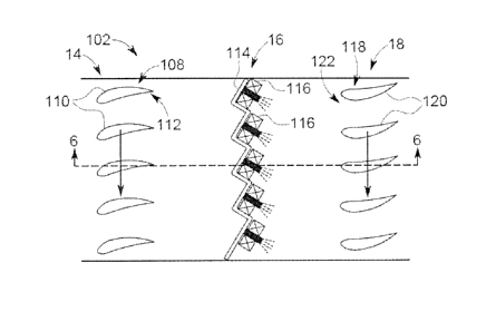
spaced rotating buckets or blades coupled within a housing. At least some
known turbine
engines are used in cogeneration facilities and power plants. Engines used in
such
applications may have high specific work and power per unit mass flow
requirements.
[0004] In at least some known gas turbines, a first set of guide vanes is
coupled
between an outlet of the compressor and an inlet of the combustor. The first
set of guide
vanes facilitates reducing swirl (i.e., removing bulk swirl) of a flow of air
discharged
from the compressor such that the flow of air is channeled in a substantially
axial
direction towards the combustor. A second set of guide vanes is coupled
between an
outlet of the combustor and an inlet of the turbine. The second set of guide
vanes
facilitates increasing swirl (i.e., reintroducing bulk swirl) of a flow of
combustion gas
discharged from the combustor such that flow angle requirements for the inlet
of the
turbine are satisfied. However, redirecting the flows of air and combustion
gas with the
first and second sets of guide vanes increases operating inefficiencies of the
gas turbine.
-1-
CA 02913910 2015-12-03
275944
Moreover, including additional components, such as the first and second sets
of guide
vanes generally adds weight, cost, and complexity to the gas turbine.
BRIEF DESCRIPTION
[0005] In one aspect, a turbine engine is provided. The turbine engine
includes a
compressor configured to discharge a flow of air at a first flow angle and a
combustor
coupled downstream from the compressor. The combustor is configured to combust
the
flow of air with fuel to form a flow of combustion gas discharged from the
combustor at a
second flow angle. The turbine engine also includes a turbine coupled
downstream from
the combustor. The turbine includes an inlet configured to receive the flow of
combustion gas having a flow angle within a predetermined range, wherein the
combustor is oriented such that the second flow angle is within the
predetermined range.
[0006] In another aspect, a method of assembling a turbine engine is provided.
The
method includes coupling a combustor downstream from a compressor configured
to
discharge a flow of air at a first flow angle. The combustor is configured to
combust the
flow of air with fuel to form a flow of combustion gas configured to discharge
from the
combustor at a second flow angle. The method also includes coupling a turbine
downstream from the combustor, the turbine comprising an inlet configured to
receive the
flow of combustion gas from the combustor having a flow angle within a
predetermined
range, and orienting the combustor such that the second flow angle is within
the
predetermined range.
DRAWINGS
[0007] These and other features, aspects, and advantages of the present
disclosure will
become better understood when the following detailed description is read with
reference
to the accompanying drawings in which like characters represent like parts
throughout the
drawings, wherein:
[0008] FIG. 1 is a schematic illustration of an exemplary gas turbine engine;
-2-
CA 02913910 2015-12-03
275944
[0009] FIG. 2 is an enlarged schematic illustration of an exemplary combustion
assembly that may be used with the gas turbine engine shown in FIG. 1;
[0010] FIG. 3 is a schematic illustration of an exemplary flow path of the
combustion
assembly along line 3-3 shown in FIG. 2;
[0011] FIG. 4 is an enlarged schematic illustration of an alternative
combustion
assembly that may be used with the gas turbine engine shown in FIG. 1;
[0012] FIG. 5 is a schematic illustration of an exemplary flow path of the
combustion
assembly along line 5-5 shown in FIG. 4; and
[0013] FIG. 6 is a schematic illustration of the flow path shown in FIG. 3
along line 6-6
shown in FIG. 3.
[0014] Unless otherwise indicated, the drawings provided herein are meant to
illustrate
features of embodiments of the disclosure. These features are believed to be
applicable in
a wide variety of systems comprising one or more embodiments of the
disclosure. As
such, the drawings are not meant to include all conventional features known by
those of
ordinary skill in the art to be required for the practice of the embodiments
disclosed
herein.
DETAILED DESCRIPTION
[0015] In the following specification and the claims, reference will be made
to a
number of terms, which shall be defined to have the following meanings.
[0016] The singular forms "a", "an", and "the" include plural references
unless the
context clearly dictates otherwise.
[0017] "Optional" or "optionally" means that the subsequently described event
or
circumstance may or may not occur, and that the description includes instances
where the
event occurs and instances where it does not.
-3-
CA 02913910 2015-12-03
275944
[0018] Approximating language, as used herein throughout the specification and
claims, may be applied to modify any quantitative representation that could
permissibly
vary without resulting in a change in the basic function to which it is
related.
Accordingly, a value modified by a term or terms, such as "about",
"approximately", and
"substantially", are not to be limited to the precise value specified. In at
least some
instances, the approximating language may correspond to the precision of an
instrument
for measuring the value. Here and throughout the specification and claims,
range
limitations may be combined and/or interchanged. Such ranges are identified
and include
all the sub-ranges contained therein unless context or language indicates
otherwise.
[0019] Embodiments of the present disclosure relate to turbine engines and
methods of
assembling thereof. More specifically, the turbine engines described herein
include a
combustor that operates with bulk swirl flow of combustion gas channeled
towards an
inlet of a turbine. The turbine generally includes at least one row of
rotating buckets, or
rotor blades, coupled to a hub in a fixed orientation and the flow of
combustion gas
channeled towards the turbine needs to have a flow angle within a
predetermined range to
ensure the bulk swirl requirements at the inlet of the turbine are satisfied.
As such, an
orientation of the bulk swirl combustor is selected to ensure the flow of
combustion gas
discharged towards the turbine has a flow angle within the predetermined
range.
Leveraging bulk swirl combustors to satisfy flow angle requirements of the
turbine
enables removal of one or both of guide vanes and turbine nozzles positioned
at opposing
ends of the combustor. Moreover, removing turbine nozzles from the turbine
engine
reduces the complexity of the turbine engine by eliminating component cooling
requirements with compressor bleed air. As such, a length of the turbine is
decreased, a
weight of the turbine engine is reduced, and turbine efficiency is increased.
[0020] As used herein, the terms "axial" and "axially" refer to directions and
orientations that extend substantially parallel to a centerline of the turbine
engine.
Moreover, the terms "radial" and "radially" refer to directions and
orientations that
extend substantially perpendicular to the centerline of the turbine engine. In
addition, as
used herein, the terms "circumferential" and "circumferentially" refer to
directions and
-4-
CA 02913910 2015-12-03
275944
orientations that extend arcuately about the centerline of the turbine engine.
It should
also be appreciated that the term "fluid" as used herein includes any medium
or material
that flows, including, but not limited to, air, gas, liquid and steam.
[0021] FIG. 1 is a schematic illustration of a gas turbine engine 10 including
a low
pressure compressor 12, a high pressure compressor 14, and a combustor 16
coupled
downstream from high pressure compressor 14. Gas turbine engine 10 also
includes a
high pressure turbine 18 coupled downstream from combustor 16, a low pressure
turbine
20 coupled downstream from high pressure turbine 18, and a power turbine 22
coupled
downstream from low pressure turbine 20.
[0022] In operation, air flows through low pressure compressor 12 and
compressed air
is supplied from low pressure compressor 12 to high pressure compressor 14.
The
compressed air is discharged towards combustor 16 and mixed with fuel to form
a flow of
combustion gas discharged towards turbines 18 and 20. The flow of combustion
gas
drives turbines 18 and 20 about a centerline 24 of gas turbine engine 10.
[0023] FIG. 2 is an enlarged schematic illustration of an exemplary combustion
assembly 100 that may be used with gas turbine engine 10 (shown in FIG. 1),
and FIG. 3
is a schematic illustration of an exemplary flow path 102 of combustion
assembly 100
along line 3-3 (shown in FIG. 2). In the exemplary embodiment, compressor 14
discharges a flow of air 104 towards combustor 16, and combustor 16 combusts
the flow
of air 104 with fuel (not shown) to form a flow of combustion gas 106. The
flow of
combustion gas 106 is discharged from combustor 16 towards turbine 18.
[0024] Referring to FIG. 3, compressor 14 includes a row 108 of rotor blades
110
defining an outlet 112 of compressor 14. Rotor blades 110 are in a first fixed
orientation
relative to centerline 24 such that the flow of air 104 (each shown in FIG. 3)
is discharged
from compressor 14 at a first flow angle. As used herein, "flow angle" is
defined as a
ratio of circumferential velocity to axial velocity of a flow of fluid.
-5-
CA 02913910 2015-12-03
275944
[0025] Combustor 16 is coupled downstream from compressor 14 and configured to
combust the flow of air 104 with fuel to form the flow of combustion gas 106
discharged
from combustor 16. More specifically, combustor 16 is a bulk swirl combustor
in a
second fixed orientation relative to centerline 24 such that the flow of
combustion gas
106 is discharged from combustor 16 at a second flow angle. For example, in
the
exemplary embodiment, combustor 16 includes a corrugated combustor dome 114
and a
plurality of combustion devices 116 coupled to corrugated combustor dome 114.
As
such, combustion devices 116 are in the second fixed orientation causing the
flow of
combustion gas 106 to be discharged at the second flow angle. The second fixed
orientation is selected such that the second flow angle is within a
predetermined range to
satisfy the flow angle requirements of inlet 122, as will be described in more
detail
below. More specifically, the orientation of combustor 16 is selected as a
function of a
velocity gradient between the flow of air entering combustor 16 and the flow
of
combustion gas discharged from combustor 16. The velocity gradient is induced
by the
addition of heat during the combustion process. In an alternative embodiment,
combustor
16 is any bulk swirl combustor that enables gas turbine engine 10 to function
as described
herein. For example, in some embodiments, combustor 16 includes a trapped
vortex
cavity configuration.
[0026] Turbine 18 is coupled downstream from combustor 16 and includes a row
118
of rotor blades 120 in a third fixed orientation defining an inlet 122 of
turbine 18.
Combustion gas 106 channeled towards turbine 18 needs to have a flow angle
within a
predetermined range to satisfy the flow angle requirements of inlet 122, and
the
predetermined range is based on an orientation of rotor blades 120. As
described above,
combustor 16 is in a second fixed orientation such that the flow of air 104
enters
combustor 16 at the first flow angle, and the flow of combustion gas 106 is
discharged
from combustor 16 at the second flow angle. The orientation of combustor 16 is
selected
based on a difference between the first flow angle and the predetermined
range, and an
expected difference between flow angles of fluid entering and being discharged
from
combustor 16. As such, the second fixed orientation of combustor 16 is
selected to
-6-
CA 02913910 2015-12-03
275944
ensure the second flow angle is within the predetermined range for satisfying
the flow
angle requirements of inlet 122.
[0027] FIG. 4 is an enlarged schematic illustration of an alternative
combustion
assembly 124 that may be used with gas turbine engine 10 (shown in FIG. 1),
and FIG. 5
is a schematic illustration of an exemplary flow path 126 of combustion
assembly 124
along line 5-5 (shown in FIG. 4). In the exemplary embodiment, combustion
assembly
124 includes a variable guide vane assembly 128 positioned between a last
stage rotor
(not shown) of compressor 14 and combustor 16. Variable guide vane assembly
128
includes a plurality of variable guide vanes 130. Variable guide vanes 130 are
also
selectively actuated based on the operating condition of gas turbine engine
10, as will be
described in more detail below. In the exemplary embodiment, compressor 14
discharges
a flow of air 104 through variable guide vane assembly 128 and towards
combustor 16,
and combustor 16 combusts the flow of air 104 with fuel (not shown) to form a
flow of
combustion gas 106. The flow of combustion gas 106 is discharged from
combustor 16
towards turbine 18.
[0028] Variable guide vane assembly 128 is positioned between compressor 14
and
combustor 16 to ensure the flow angle of combustion gas 106 channeled towards
turbine
18 is within the predetermined range for inlet 122 across a wide range of
operating
conditions for gas turbine engine 10. When the first fixed orientation of
rotor blades 110,
the second fixed orientation of combustor 16, and the predetermined range of
acceptable
flow angles of fluid entering turbine 18 remain constant, variable guide vane
assembly
128 is selectively operable to modify the flow angle of the flow of air 104
discharged
from compressor 14 and channeled towards combustor 16.
[0029] Referring to FIG. 5, variable guide vanes 130 are selectively actuated
to rotate
about an axis (not shown) extending substantially radially from centerline 24
(shown in
FIG. 4). For example, when gas turbine engine 10 (shown in FIG. 1) is in a
steady state
operational mode, variable guide vanes 130 actuate into a position such that
the flow
angle of the flow of air 104 discharged from combustor 16 is within the
predetermined
-7-
CA 02913910 2015-12-03
275944
range for inlet 122. When gas turbine engine 10 is in an off-design
operational mode,
variable guide vanes 130 actuate into a position that modifies the flow angle
of the flow
of air 104 before entering combustor 16. As such, the orientation of variable
guide vanes
130 is selected such that the second flow angle of the flow of combustion gas
106
discharged from combustor 16 is within the predetermined range for inlet 122.
[0030] FIG. 6 is a schematic illustration of flow path 102 along line 6-6
(shown in FIG.
3). In the exemplary embodiment, flow path 102 extends between compressor 14
and
turbine 18 in a substantially axial direction along centerline 24. Flow path
102 is defined
by an outer flow duct 132 and an inner flow duct 134. Flow path 102 also
includes a
variable cross-sectional area defined between outer and inner flow ducts 132
and 134
along the substantially axial direction. The outer and inner flow ducts 132
and 134 are
tailored such that a mean radial location 135 extending therebetween, and a
cross-
sectional area defined therebetween, facilitates ensuring the flow angle of
combustion gas
106 (shown in FIG. 2) is within the predetermined range for inlet 122. For
example, flow
path 102 includes a first section 136 extending between compressor 14 and
combustor 16,
and a second section 138 extending between combustor 16 and turbine 18. The
cross-
sectional area of first section 136 progressively increases in size from
compressor 14 to
combustor 16, and the cross-sectional area of second section 138 progressively
decreases
in size from combustor 16 to turbine 18. Progressively increasing the cross-
sectional area
of first section 136 decelerates the flow of air 104 (shown in FIG. 3)
channeled towards
combustor 16, and progressively decreasing the cross-sectional area of second
section
138 accelerates the flow of combustion gas 106 channeled towards turbine 18.
As such,
the swirl of the flows of fluid channeled through flow path 102 is selectively
modified to
ensure the second flow angle of combustion gas 106 is within the predetermined
range
for inlet 122.
[0031] The turbine engine and methods described herein relate to leveraging
bulk swirl
combustors to enable a component architecture of the turbine engine to be
modified. In
the exemplary embodiment, an orientation of a bulk swirl combustor is selected
to ensure
a flow of combustion gas discharged towards a turbine has a flow angle within
a
-8-
CA 02913910 2015-12-03
275944
predetermined range. Leveraging
bulk swirl combustors to satisfy flow angle
requirements of the turbine enables removal of one or both of guide vanes and
turbine
nozzles positioned at opposing ends of the combustor. Moreover, in one
embodiment,
variable guide vanes or a variable-area turbine flow path is implemented to
ensure flow
angle requirements for the turbine are satisfied at a wide range of
operational modes, for
example.
[0032] An exemplary technical effect of the turbine engine and methods
described
herein includes at least one of: (a) removing redundant components from the
turbine
engine; (b) reducing a weight and length of the turbine engine; and (c)
increasing an
operational efficiency of the turbine engine.
[0033] Exemplary embodiments of the gas turbine engine are described above in
detail.
The assembly is not limited to the specific embodiments described herein, but
rather,
components of systems and/or steps of the methods may be utilized
independently and
separately from other components and/or steps described herein. For example,
the
configuration of components described herein may also be used in combination
with
other processes, and is not limited to practice with only gas turbine engines
and related
methods as described herein. Rather, the exemplary embodiment can be
implemented
and utilized in connection with many applications where leveraging bulk swirl
combustion is desirable.
[0034] Although specific features of various embodiments of the present
disclosure
may be shown in some drawings and not in others, this is for convenience only.
In
accordance with the principles of embodiments of the present disclosure, any
feature of a
drawing may be referenced and/or claimed in combination with any feature of
any other
drawing.
[0035] While there have been described herein what are considered to be
preferred and
exemplary embodiments of the present invention, other modifications of these
embodiments falling within the scope of the invention described herein shall
be apparent
to those skilled in the art.
-9-